Table of Contents
Advertisement
USER AND INSTALLATION MANUAL
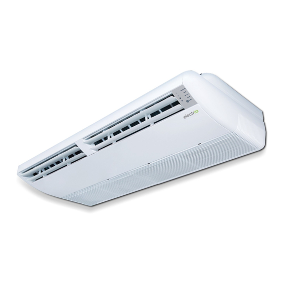
FLOOR & CEILING MOUNTED DC INVERTER SPLIT AIR
Please read this user manual before using this innovative
Air Conditioner and keep it safe for future reference.
Visit our page
www.electriQ.co.uk
CONDITIONER WITH HEAT PUMP
eiQ-FC18K
eiQ-FC24K
eiQ-FC36K
Thank you for choosing electriQ
18,000 BTU
24,000 BTU
36,000 BTU
for our entire range of Intelligent Electricals
Advertisement
Table of Contents

Related Manuals for ElectrIQ eiQ-FC18K


Summary of Contents for ElectrIQ eiQ-FC18K
- Page 1 18,000 BTU eiQ-FC24K 24,000 BTU eiQ-FC36K 36,000 BTU Thank you for choosing electriQ Please read this user manual before using this innovative Air Conditioner and keep it safe for future reference. Visit our page www.electriQ.co.uk for our entire range of Intelligent Electricals...
-
Page 2: Table Of Contents
CONTENTS CONTENTS SAFETY INSTRUCTIONS PRODUCT DESCRIPTION HOW AIR SPLIT CONDITIONERS WORK DISPLAY PANEL REMOTE CONTROL REPLACING THE BATTERIES FILTERS START OF SEASON END OF SEASON INSTALLATION GUIDE TOOLS RECOMMENDED FOR INSTALLATION INSTALLATION OF THE OUTDOOR UNIT PIPELINES CONNECTION & AIR PURGING ELECTRICAL WIRING DIAGRAMS TROUBLESHOOTING AND SELF DIAGNOSIS TECHNICAL SPECIFICATIONS... -
Page 3: Safety Instructions
SAFETY INSTRUCTIONS Important! • Carefully read the instructions before operating the unit. • This appliance comprises of an indoor and an outdoor unit. The indoor slim evaporator is designed exclusively for indoor floor, wall or ceiling installations while the external condenser should be installed outside while still away from flood water or snow line. -
Page 4: Product Description
Energy Saving and Unit Safety Protection Tips • Do not cover or restrict the airflow from the outlet or inlet grills both on the indoor and outdoor units. • For maximum performance, the minimum distance from a wall or objects should be 50cm. •... -
Page 5: How Air Split Conditioners Work
HOW AIR SPLIT CONDITIONERS WORK COOLING MODE WALL MOUNTED The compressor (6) in the external unit compresses the refrigerant into a high-temperature, high- pressure gas. When this gas flows along the cooling fins of the condenser (7), heat is exuded and the gas condenses into a liquid, which is then led to the evaporator (1) in the indoor unit. - Page 6 ALTERNATIVE WAYS TO MOUNT CEILING MOUNTED FLOOR MOUNTED...
-
Page 7: Display Panel
DISPLAY PANEL DEFROST INDICATOR TIMER ON INDICATOR FAULT PROTECTION LED ON LIGHT TMER ALARM REMOTE SENSOR The air conditioner has a simple to read display panel. Shows the unit is switched on and (GREEN) working Defrost protection activated. In cold temperatures the unit will enter defrost mode to prevent compressor damage (RED) -
Page 8: Remote Control
REMOTE CONTROL DIAGRAM INCREASE TEMPERATURE Increase the desired temperature. MODE Select between automatic, cooling, dehumidification, fan and heating REDUCE TEMPERATURE modes. Decrease the desired temperature. INCREASE FAN SPEED Increase the fan speed by one level. Please note: When on the highest POWER fan speed it will change to auto. - Page 9 REMOTE CONTROL DISPLAY OTHER ICONS MODES AUTO MODE CLOCK COOLING MODE SLEEP FUNCTION DEHUMIDIFIER MODE TURBO FUNCTION FAN MODE ECON FUNCTION HEATING MODE CLEANING FUNCTION TEMPERATURE DISPLAY REMOTE LOCKED CURRENT TEMPERATURE BATTERY LOW Ranges between 16 - 32̊ C FAN SPEED AUTO CONFIG LENGTH OF BAR POWER SAVING MODE...
-
Page 10: Replacing The Batteries
REMOTE CONTROL FUNCTIONS POWER This button will turn the air conditioner On and Off. 1. When first powered on, air conditioner will start with the default settings: • Desired temperature 25°C • Automatic mode and Automatic fan speed. • Vertical and Horizontal Swing. •... - Page 11 TIMER The timer can be used as a start timer or a shutdown timer and can be set between 1 hour and 24 hours in 1 hour increments. This is a one use timer, and multiple timers cannot be combined. START TIMER 1.
- Page 12 IMPORTANT INFORMATION AUTO RESTART The air conditioner will automatically restart when electricity is restored after a power cut. If in doubt, check the settings. RANGE OF INTERNAL THERMOSTAT The internal thermostat can be set at a desired temperature between 16 and 32°C. Note that whether the desired value is achieved depends on the room size, temperature and insulation of the room.
-
Page 13: Filters
FILTERS Turn off the appliance from the consumer unit before attempting to service the filters. Never attempt servicing the unit while the power is on. If the unit is celling mounted, please ensure enough space is left to service the filters Identify the filters and remove them as per the procedure bellow Find the groove on the panel and pull the filter out... -
Page 14: Start Of Season
Use a vacuum cleaner to remove dirt. If the dust filter is very dirty, it may be washed in lukewarm water with a very small amount of neutral detergent. Rinse well and allow to dry completely (not in direct sunlight or near a source of heat). Reverse the filter removal procedure and push back the clean filter. -
Page 15: Installation Guide
INSTALLATION GUIDE SAFETY • Only qualified personnel should install this appliance. • This installation manual is intended for use by individuals possessing adequate backgrounds and qualifications in electrical, electronic, refrigerant and mechanical fields. • Any attempt to install or repair the appliance may result in personal injury and property damage. - Page 16 INDOOR UNIT POSITION AND SPACING The air inlet and outlet vent should be away from any obstruction, ensuring that there is good airflow through the whole air- conditioned space. Select a position where the condensing water can be easily drained out, and the indoor unit can be easily connected to outdoor unit.
- Page 17 INSTALL DIMENSION REQUIREMENTS FOR OUTDOOR UNIT Position Minimum Clearance Left 50 cm Right 50 cm Back 30-50 cm Front 200 cm OUTDOOR UNIT POSITION A convenient position, dry and well ventilated, outside of direct sunlight or strong winds, which is not on a flood line and where noise and airflow does not cause interference or inconvenience.
-
Page 18: Tools Recommended For Installation
TOOLS RECOMMENDED FOR INSTALLATION Tape Measure Electric Drill Screwdrivers Hammer Core Hole Cutter Pencil and Chalk Spirit Level Number 14 (7mm) Masonry Drill 7mm Wall Plugs Small Stepladder 1.5 inch number 10 Protective Glasses screws and Mask Pipe and Cable Circuit Breaker 4 inch Plastic Ties 2 Inch Pipe Clips... - Page 19 INSTALLING THE INDOOR UNIT • Select the location of the internal unit, determining the fixing direction and where the pipework will go. • Check that the wall where the pipework will be placed through is clear of any wiring or other internal pipework or structures, before drilling a 90mm diameter hole (slanted slightly downwards).
- Page 20 • Once the indoor unit is hung in place, the wiring and pipework can be connected. If space is tight you may need to fit the copper pipes, drain pipes, control and electrical wires before you permanently hang the indoor unit The installation steps for embedded style are basically the same with the hanging style, but remove the left and right panels of the indoor unit and then embed half of the unit body into the ceiling showing up only the back panel and top panel.
- Page 21 ALTERNATIVE CEILING MOUNTING METHOD USING LIFTING BOLTS Matching the structure of the ceiling, set the thread pitch based on the size of this unit as bellow WOODEN STRUCTURES STEEL SKELETON STRUCTURES Place the square bar on the girders and install the lifting bolts. Set directly on the supporting steel Different type of bolts or inserts can be also used.
- Page 22 FLOOR / WALL MOUNTING For floor or wall mounting use embedded or expandable bolts strong enough for the type of wall. Install the unit with the control panel facing up similar to a radiator and make sure it is correctly aligned and level.
-
Page 23: Installation Of The Outdoor Unit
Electrical cable specs Indoor power Indoor/outdoor Pipes Outdoor power Model supply line signal line supply line(quantity, (quantity, (quantity, diameter, length) diameter, length) diameter, length) (Φ6.35×0.7+Φ12.7×0.75)×5m eiQ-FC18K 3×2.5mm2 4×2.5mm2x6.3m eiQ-FC24K (Φ9.52×0.75+Φ15.88×0.8)×5m 3×2.5mm2 4×2.5mm2x6.3m eiQ-FC36K (Φ9.52×0.75+Φ15.88×0.8)×5m 3×4mm2 4×2.5mm2x6.3m DIMENSIONS FOR PARALLEL UNITS INSTALLATIONS 300mm(1')min... - Page 24 FOOTPRINT OF THE OUTDOOR UNITS D I M E NS I ONS (mm) Unit eiQ-FC18...
- Page 25 DIMENSIONS ( mm) Unit eiQ-FC24 DIMENSIONS ( mm) Unit eiQ-FC36 1030...
-
Page 26: Pipelines Connection & Air Purging
PIPELINES CONNECTION & AIR PURGING No dust or any other particles, air or moisture should be allowed to enter the air conditioning system. Careful attention should be paid when pipeline connection for outdoor unit is made. Try to avoid repeated curves as much as possible; otherwise, damage to the copper pipes may occur. - Page 27 TORQUE TO BE USED TO TIGHTEN THE CONNECTIONS Outside Strengthened diameter of Tightening tightening torque the copper torque(N·cm) (N·cm) pipe (mm) Φ6.3 or Φ6 1570(160kgf·cm) 1960(200kgf·cm) Φ9.52 or 2940(300kgf·cm) 3430(350kgf·cm) Φ9 Φ12.7 or 4900(500kgf·cm) 5390(550kgf·cm) Φ12 Φ16 7360(750kgf·cm) 7850(800kgf·cm) Φ19 9720(900kgf·cm) 11860(1210kgf·cm) ADDING REFRIGERANT...
- Page 28 If oil return elbow radius R ≤100mm, oil return elbows must be located per 5 m as shown; when the height difference between indoor and outdoor unit exceeds five meters, oil reserve elbow and backstop elbow should be set according to the relative position of outdoor unit and indoor unit.
- Page 29 NOTES: The copper pipe used in the refrigeration lines is very soft, high pressure copper and prone to get damaged if not handled correctly. Try to avoid getting it bent or stretched. Always use foam protectors (sleeve) and a plastic ring before getting the pipes through the wall. Those will help prevent damage to the pipes.
-
Page 30: Electrical Wiring Diagrams
ELECTRICAL WIRING DIAGRAMS For ease of installation the indoor unit of most models will be provided pre wired with 5 metres of interconnecting cable. eiQ-FC18K eiQ-FC24K Outdoor Indoor Unit Unit eiQ-FC36K... - Page 31 CONNECTION OF ELECTRICAL POWER AND SIGNAL CABLES Only allow qualified engineers that can follow local regulations to install the equipment and the power. Warning: The air conditioner unit must be securely grounded! If the power cord or signal cable of the appliance is damaged, it must be replaced with a new cord with same or better specifications.
-
Page 32: Troubleshooting And Self Diagnosis
TROUBLESHOOTING AND SELF DIAGNOSIS electriQ air conditioners have an advanced self-diagnosis system allowing them to display the service information Indoor unit error code list Check Description Unit Display Status Display Code Display LED (light flashing) (unit & remote) Indoor Three-phase power phase... - Page 33 OUTDOOR UNIT ERROR CODE LIST Display Error description Display Error description Phase protection (reserved) Communication error between outdoor unit and (reserved) indoor unit Indoor room temperature (T1) sensor error (reserved) Outdoor unit current error cannot recover Indoor coil middle temperature (T2) sensor error Display P3 error for 3 times within 60 minutes Indoor coil outlet temperature (T2B) sensor error...
- Page 34 The kw is converted approximatively to hp in the pcb logic as 5.3kw= 2HP, 7.1kw= 3HP, 10.5kw= 4HP, 14kw= 5HP. If for eiq-FC18K e.g. max capacity is measured as 3xHP=6 (A) as in code (2). The variable DC inverter operating Variable DC inverter 22 ⁰...
- Page 35 for 18-36K, it will show 0-7 it's according to outdoor unit DC motor variable speed for 48K, it shows always 0 due to fixed speed AC motor T2/T2B average T2 evaporator / T2B evaporator outlet temperature (Celsius) temperature T3 pipe temperature T3 condenser outlet temperature (Celsius) T4 environmental Outdoor temperature (Celsius)
-
Page 36: Technical Specifications
TECHNICAL SPECIFICATIONS Model eiQ-FC18K-V2 eIQ-FC24K-V2 Power supply V/Ph/Hz 220~240/1/50 220~240/1/50 Capacity 2.0-5.3-5.6 3.5-7.0-8.0 Power input 420-1640-2100 600-2200-3000 Cooling Current input 2.1-10.1 2.5-13 3.23 3.18 SEER Capacity 2.5-5.9-6.0 4.5-7.7-8.5 Input 500-1530-1940 1500-1980-2600 Heating Rated current 2.5-9.2 5.5-11 3.86 3.89 SCOP Energy rate... - Page 37 Model eIQ-FC36K-V2 Power supply V/Ph/Hz 220~240/1/50 Capacity 6.6-10.5-12.8 Power input 740-3170-3900 Cooling Current input 2.8-13.6-20 3.31 SEER Capacity 7.35-11.5-13.2 Input 1100-3395-4000 4.2-14.7-20.4 Heating Rated current 3.39 SCOP Energy rate Cooling Energy rate Heating Max. power input 4800 Max. current input Model DR-310-120LD-8 Brand...
- Page 38 WARRANTY INFORMATION electriQ guarantee provides cover against material or manufacturing faults. This means that if your air conditioner develops a fault during the guarantee period, we will arrange for it to be repaired or replaced. Faults arising from a faulty installation are specifically excluded. The system must be serviced annually by qualified personnel.
-
Page 39: Appendix
• Do not pierce or burn. • Be aware that refrigerants may not contain an odour. electriQ UK SUPPORT www.electriQ.co.uk/support Please, for your own convenience, check the troubleshooting guide before calling the service line. If the unit still fails to operate call: 0871 620 1057 or complete the online form Office hours: 9AM - 5PM Monday to Friday www.electriQ.co.uk...
Need help?
Do you have a question about the eiQ-FC18K and is the answer not in the manual?
Questions and answers