BUSCH R 5 Series Instruction Manual
Oil-lubricated rotary vane vacuum pumps
Hide thumbs
Also See for R 5 Series:
- User manual ,
- Instruction manual (68 pages) ,
- Instructions manual (52 pages)

Subscribe to Our Youtube Channel
Related Manuals for BUSCH R 5 Series


Summary of Contents for BUSCH R 5 Series
- Page 1 Instruction Manual Oil-Lubricated Rotary Vane Vacuum Pumps RA 0750 A Ateliers Busch S.A. Zone industrielle, 2906 Chevenez Switzerland 0870565413/A0001_en / Original instructions / Modifications reserved 08/03/2019...
-
Page 2: Table Of Contents
Table of Contents Table of Contents 1 Safety........................... 4 2 Product Description ..................... 5 2.1 Operating Principle....................6 2.2 Application ......................6 2.3 Standard Features....................6 2.3.1 Water Cooling ...................6 2.3.2 Variable-Frequency Drive................6 2.3.3 Gas Ballast Valve..................6 2.3.4 Temperature Switch "Gas" ................7 2.4 Optional Accessories..................... - Page 3 Table of Contents 12 Technical Data ......................29 13 Oil ..........................29 14 EU Declaration of Conformity ..................30 0870565413_RA0750A_A0001_IM_en...
-
Page 4: Safety
Safety Prior to handling the machine, this instruction manual should be read and understood. If anything needs to be clarified, please contact your Busch representative. Read this manual carefully before use and keep for future reference. This instruction manual remains valid as long as the customer does not change anything on the product. -
Page 5: Product Description
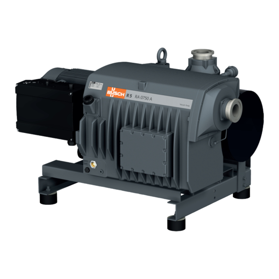
Product Description | 2 Product Description CWO WHE Suction connection Discharge connection Directional arrow Variable-frequency drive Oil fill plug Exhaust filter Oil sight glass Nameplate Oil drain plug Oil filter Eye bolt Oil separator Gas ballast valve Filter material Water-oil heat exchanger Temperature switch Float valve Cooling water inlet... -
Page 6: Operating Principle
Conveying of other media leads to an increased thermal and/or mechanical load on the machine and is permissible only after a consultation with Busch. The machine is intended for the placement in a non-potentially explosive environment. The machine is designed for indoor installation, in case of outdoor installation, ask your Busch representative in order to take specific precautions. -
Page 7: Temperature Switch "Gas
Product Description | 2 2.3.4 Temperature Switch "Gas" The temperature switch monitors the gas temperature of the machine. The machine must be stopped when the gas reaches 110 °C. 2.4 Optional Accessories 2.4.1 Temperature Switch "Oil" The temperature switch monitors the oil temperature of the machine. Depending on the oil type, the machine must be stopped when the oil reaches a certain temperature, see Oil [► 29]. -
Page 8: Transport
3 | Transport Transport WARNING Suspended load. Risk of severe injury! • Do not walk, stand or work under suspended loads. NOTICE In case the machine is already filled with oil. Tilting a machine that is already filled with oil can cause large quantities of oil to in- gress into the cylinder. -
Page 9: Storage
Storage | 4 Storage • Seal all apertures with adhesive tape or reuse provided caps. NOTICE Long storage time. Risk of damage to the machine! • Due to a long storage time the capacitors of the variable-frequency drive can lose effi- ciency because of electrochemical processes. -
Page 10: Connecting Lines / Pipes
Connection [► 12]. If the machine is installed at an altitude greater than 1000 meters above sea level: • Contact your Busch representative, the motor should be derated or the ambient temperature limited. If the machine is equipped with monitoring devices or sensors: •... -
Page 11: Suction Connection
Depending on the specific order, other connection dimensions may apply. If the machine is used as part of a vacuum system: • Busch recommends the installation of an isolation valve in order to prevent the oil from flowing back to the vacuum system. -
Page 12: Cooling Water Connection
5 | Installation 5.2.3 Cooling Water Connection Cooling water inlet Cooling water outlet Water-oil heat exchanger • Connect the cooling water connections (CWI / CWO) to the water supply. Connection size: – G1/2, ISO 228-1 (CWI / CWO) • Make sure that the cooling water complies with the following requirements: Min. -
Page 13: Filling Oil
Use of an inappropriate oil. Risk of premature failure! Loss of efficiency! • Only use an oil type which has previously been approved and recommended by Busch. For oil type and oil capacity see Technical Data [► 29] and Oil [► 29]. Check oil level 0870565413_RA0750A_A0001_IM_en... -
Page 14: Electrical Connection
• Make sure that the motor of the machine will not be affected by electric or electro- magnetic disturbance from the mains; if necessary seek advice from Busch. • Connect the protective earth conductor. • Electrically connect the variable-frequency drive (VFD). -
Page 15: Wiring Diagram Three-Phase Motor
Installation | 5 • Electrically connect the motor. NOTICE Incorrect connection. Risk of damage to the motor! • The wiring diagrams given below are typical. Check the inside of the terminal box for motor connection instructions/diagrams. 5.4.4 Wiring Diagram Three-Phase Motor Delta connection (low voltage): Star connection (high voltage): Double star connection, multi-voltage... -
Page 16: Electrical Connection Of The Monitoring Devices
• Switch any two of the motor phase wires. 5.5 Electrical Connection of the Monitoring Devices NOTE In order to prevent potential nuisance alarms, Busch recommends that the control system is configured with a time delay of at least 20 seconds. 5.5.1 Wiring Diagram Temperature Switch "Gas"... -
Page 17: Wiring Diagram Level And Temperature Switch (Optional)
Installation | 5 5.5.4 Wiring Diagram Level and Temperature Switch (Optional) Part no.: 0652 563 748 Connector: M12x1, 4-pin Electrical data: U = ≤ 230 V AC (50/60 Hz) ; U = ≤ 100 V DC (50/60 Hz) ; 1 = Brown ; 2 = White ; I = ≤... -
Page 18: Commissioning
6 | Commissioning Commissioning NOTICE The machine can be shipped without oil. Operation without oil will ruin the machine in short time! • Prior to commissioning, the machine must be filled with oil, see Filling Oil [► 13]. CAUTION During operation the surface of the machine may reach temperatures of more than 70°C. -
Page 19: Conveying Condensable Vapours
Maintenance | 7 6.1 Conveying Condensable Vapours Water vapour within the gas flow is tolerated within certain limits. The conveyance of other vapours shall be agreed upon with Busch. If condensable vapours are to be conveyed: • Close the isolation •... - Page 20 Risk of injuries! Risk of premature failure and loss of efficiency! • Respect the maintenance intervals or ask your Busch representative for service. • Shut down the machine and lock against inadvertent start up. • Vent the connected lines to atmospheric pressure.
-
Page 21: Maintenance Schedule
(WHE): • Check and/or clean the water cooling sys- tem. • Contact Busch for an inspection. Every 5 years If required, overhaul the machine. * Service interval for synthetic oil, shorten the interval when using mineral oil, contact Busch Service 7.2 Oil Level Inspection... -
Page 22: Oil And Oil Filter Change
NOTICE Use of an inappropriate oil. Risk of premature failure! Loss of efficiency! • Only use an oil type which has previously been approved and recommended by Busch. 1x o-ring, part no.: 0486 000 505 Drain pan 22 / 32... - Page 23 Maintenance | 7 Busch genuine spare parts 1x oil filter (OF), part no.: 0531 000 005 Oil filter wrench For oil type and oil capacity see Technical Data [► 29] and Oil [► 29]. Check oil level 0870565413_RA0750A_A0001_IM_en 23 / 32...
-
Page 24: Exhaust Filter Change
7.4 Exhaust Filter Change 8x exhaust filter (EF) 6 mm hex key extract filter material (FM) 6 mm hex key Busch genuine spare parts, Max. admissible torque: 21 Nm 8x exhaust filter (EF), part no.: 0532 140 160 O-ring 1x filter material (FM) part no.: 0537 000 042... -
Page 25: Overhaul
• Decontaminate the machine as much as possible and state the contamination status in a ‘Declaration of Contamination’. Busch will only accept machines that come with a completely filled in and legally binding signed ‘Declaration of Contamination’. (Form downloadable from www.buschvacuum.com) Decommissioning •... -
Page 26: Spare Parts
Use of non-Busch genuine spare parts. Risk of premature failure! Loss of efficiency! • The exclusive use of Busch genuine spare parts and consumables is recommended for the correct functioning of the machine and to validate the warranty. Spare parts kit Description Part no. -
Page 27: Troubleshooting
Troubleshooting | 11 11 Troubleshooting DANGER Live wires. Risk of electrical shock. • Electrical installation work must only be executed by qualified personnel. DANGER Carry out any work on the variable-frequency drive and motor. Risk of electrical shock! • Electrical installation work must only be executed by qualified personnel. CAUTION Hot surface. - Page 28 The float valve (FV) does • Check float valve and the not work properly. oil return line, repair it if necessary (contact Busch). The machine runs at atmo- • Make sure that the ma- spheric pressure for a long chine operates under va- period.
- Page 29 Switch point / Trip signal Oil temperature [°C] In case of unfavourable ambient temperature, other oil viscosities may be used. Please consult your Busch repre- sentative for more details. To know which oil has been filled in the machine, please refer to the nameplate (NP).
- Page 30 This Declaration of Conformity and the CE-mark affixed to the nameplate are valid for the machine within the Busch scope of delivery. This Declaration of Conformity is issued under the sole responsibility of the manufacturer. When this machine is integrated into a superordinate machinery the manufacturer of the superordinate machinery (this can be the operating company, too) must conduct the conformity assessment process for the superordinate machine or plant, issue the Declaration of Conformity for it and affix the CE-mark.
- Page 31 Note...
- Page 32 Colombia Korea South Africa www.buschvacuum.com/co www.buschvacuum.com/kr www.buschvacuum.com/za info@buschvacuum.co busch@busch.co.kr info@busch.co.za Czech Republic Malaysia Spain www.buschvacuum.com/cz www.busch.com.my www.buschvacuum.com/es info@buschvacuum.cz busch@busch.com.my contacto@buschiberica.es Denmark Mexico Sweden www.buschvacuum.com/dk www.buschvacuum.com/mx www.buschvacuum.com/se info@busch.dk info@busch.com.mx info@busch.se www.buschvacuum.com 0870565413/A0001_en / © Ateliers Busch S.A.
Need help?
Do you have a question about the R 5 Series and is the answer not in the manual?
Questions and answers