Table of Contents
Advertisement
Advertisement
Table of Contents

Related Manuals for Honeywell Unipoint 2306B1000


Summary of Contents for Honeywell Unipoint 2306B1000
- Page 1 Operating Instructions Unipoint Flammable and Toxic Gas Detection Controller...
-
Page 2: Safety
Alternatively contact your local Honeywell Analytics representative. Honeywell Analytics can take no responsibility for installation and/or use of its equipment if this is not done in accordance with the appropriate issue and/or amendment of the manual. -
Page 3: Table Of Contents
UNIPOINT OPERATING MANUAL 2306M5001 MAN0638 ISSUE 7 01/2011 2 Table of Contents 1 Safety............................2 Table of Contents........................3 3 Introduction..........................4 4 Installation..........................4 4.1 Mechanical Installation......................4 4.2 Electrical Installation......................6 4.2.1 Unipoint Controller Selection.................... 6 4.2.2 Power Connection......................4.2.3 Terminal Detail........................ -
Page 4: Introduction
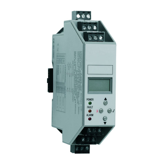
Signalpoint or Sensepoint range of toxic and oxygen detectors. It has 4 buttons: ‘s’ up, ‘t’ down, ‘x’ reset and ‘3’ OK, that are used navigate through the menus and change the configuration settings. *All Honeywell Analytics gas detectors and third party detectors subject to overall power requirements. 4 Installation... -
Page 5: Unipoint Operating Manual 2306M5001 Man0638 Issue 7
UNIPOINT OPERATING MANUAL 2306M5001 MAN0638 ISSUE 7 01/2011 The Unipoint controller is mounted on standard symmetrical ‘top hat’ DIN Rail (35 x 7.5mm). To attach the Unipoint controller to the DIN rail follow the procedure below use the Installation Diagram as reference. 1. -
Page 6: Electrical Installation
UNIPOINT OPERATING MANUAL 2306M5001 MAN0638 ISSUE 7 01/2011 4.2 Electrical Installation 4.2.1 Unipoint Controller Selection Detector Gas Type Nº Wires Unipoint Controller Required Signalpoint Flamable Toxic Sensepoint Flamable Toxic Sensepoint Plus Flamable Toxic 4.2.2 Power Connection Max number of Unipoint controllers on one DIN Bus Detector Type Max number of controllers... -
Page 7: Terminal Detail
UNIPOINT OPERATING MANUAL 2306M5001 MAN0638 ISSUE 7 01/2011 4.2.3 Terminal Detail All electrical connections except power are made via removable terminals located on the top and bottom of the controller. The power connection is made via the power connector attached to the DIN rail. -
Page 8: Generic Detector Wiring Schematics
UNIPOINT OPERATING MANUAL 2306M5001 MAN0638 ISSUE 7 01/2011 4.2.5 Generic Detector Wiring Schematics To connect the detector to the Unipoint use a 2 or 3 wire cable (as appropriate) that is suitably armoured (e.g. Steel Wire Armour) or conduit according to local requirements. Acceptable wire cross sectional area is from 0.5 to 1.5mm with overall screen. -
Page 9: Maximum Cable Lengths
UNIPOINT OPERATING MANUAL 2306M5001 MAN0638 ISSUE 7 01/2011 4.3 Maximum Cable Lengths 4.3.1 mA Detectors To calculate the maximum cable run length from power source to the detector refer to the following example diagram and formula. Rloop = (Vcontroller - 1.5V - Vdetector min) / Idetector Maximum cable run length = Rloop / cable per metre resistance where: Rloop = maximum working cable loop resistance... -
Page 10: Default Configuration
UNIPOINT OPERATING MANUAL 2306M5001 MAN0638 ISSUE 7 01/2011 5 Default Configuration Unipoint has user configurable settings that allow the set up of the system to individual application requirements. Unipoint is supplied from the factory with a default configuration. These configurations are based on settings typically used in gas detection systems. Details of how to reconfigure Unipoint are given in section 7. -
Page 11: Switch On
UNIPOINT OPERATING MANUAL 2306M5001 MAN0638 ISSUE 7 01/2011 6 Switch On After connecting power, the controller enters a self test routine: All LCD segments flash, the fault and alarm LED flash, the sounder operates three times, the RAM, ROM and EEPROM are checked and the software version is displayed. -
Page 12: Setting Detector Type (Ma Version Only)
UNIPOINT OPERATING MANUAL 2306M5001 MAN0638 ISSUE 7 01/2011 23. When the reading is stable press 3. 24. ‘---’ is displayed while calculating the new span. 25. The display then shows the new span value. If span fails ‘FFF’ is displayed. 26. -
Page 13: Normal Operation
UNIPOINT OPERATING MANUAL 2306M5001 MAN0638 ISSUE 7 01/2011 8 Normal Operation In normal operation the green Power LED is illuminated and the 1st line of the LCD shows the current gas reading. The 2nd line is used to display text codes that provide additional informa- tion about the type of event that has occurred. -
Page 14: Normal Operation Lcd Event Codes
UNIPOINT OPERATING MANUAL 2306M5001 MAN0638 ISSUE 7 01/2011 8.2 Normal Operation LCD Event Codes The display event codes are shown below: NORMAL OPERATION DISPLAY TEXT CODES CODE EVENT TYPE Alarm point 1 exceeded Alarm point 2 exceeded Alarm point 3 exceeded All outputs disabled Fault. -
Page 15: Fault Codes
UNIPOINT OPERATING MANUAL 2306M5001 MAN0638 ISSUE 7 01/2011 8.5 Fault Codes Below are the fault codes and recommended action to clear the fault. FAULT CODE DESCRIPTION TROUBLE SHOOT Sensor / wiring fault Check sensor / field wiring Negative drift Calibrate detector Excessive interference Check field wiring RAM fault... - Page 16 UNIPOINT OPERATING MANUAL 2306M5001 MAN0638 ISSUE 7 01/2011...
-
Page 17: Ranges And Units
UNIPOINT OPERATING MANUAL 2306M5001 MAN0638 ISSUE 7 01/2011 10 Ranges and Units Below are the possible combinations of range and units for the two Unipoint Controller types: Unipoint Controller Units Available Full Scale Ranges %LEL 2.00; 3.00; 5.00; 10.0; 15.0; 20.0; 25.0; 50.0 of 100 %VOL mV or mA version 2.00;... -
Page 18: Alarm Relay Off Delay
12 Maintenance The Unipoint controller has no user serviceable parts. Honeywell Analytics recommend that the controller’s configuration and operation are checked annually. The gas detectors connected to the controller should be checked and if necessary zero and... -
Page 19: Ordering Information
Honeywell Analytics shall not be liable for any loss or damage whatsoever or howsoever oc- casioned which may be a direct or indirect result of the use or operation of the Contract Goods by the Buyer or any Party. -
Page 20: Appendix A- Specification
UNIPOINT OPERATING MANUAL 2306M5001 MAN0638 ISSUE 7 01/2011 15 Appendix A- Specification Specification The Unipoint controller provides integrators with a flexible and low cost solution to the many applications requiring flammable, toxic or oxygen gas detection to be incorporated into their control systems. Unipoint is designed to use industry standard DIN rail allowing it to be easily installed into many different types of plastic or metal, indoor or outdoor, hazardous or non hazardous area enclosures. -
Page 21: Approvals
UNIPOINT OPERATING MANUAL 2306M5001 MAN0638 ISSUE 7 01/2011 16 Approvals Unipoint is performance approved to EN60079-29-1 (measuring function) for use with Signal- point, Sensepoint (Combustible) and any 4-20 mA device. Caution: Unipoint is a safe area device. It must not be installed in hazardous areas. Special Conditions of Use 1. -
Page 22: Ec Declaration Of Conformity
Name: Steve Hamilton Position: Senior Regulatory Compliance Engineer Date: 9 September 2010 Declaration Number: 2004Y0014_01/A03209 Declaration of Conformity in accordance with EN ISO/IEC 17050-1:2010 Registered Office: Honeywell House, Arlington Business Park, Bracknell, Berkshire RG12 1EB Registered in England No. 412070... -
Page 23: Notes
UNIPOINT OPERATING MANUAL 2306M5001 MAN0638 ISSUE 7 01/2011 18 Notes...
Need help?
Do you have a question about the Unipoint 2306B1000 and is the answer not in the manual?
Questions and answers