Table of Contents
Advertisement
FRWY-LS1046AGSG
Layerscape FRWY-LS1046A Board Getting Started Guide
Supports FRWY-LS1046A Board Revision B
Rev. 0 - 26 April 2019
1 Introduction
®
The Layerscape
LS1046A Freeway (FRWY-LS1046A) board is a high-
performance development platform that supports the QorIQ
architecture processor capable of supporting more than 32000 CoreMark
performance. This document describes different board components and
explains how to set up and boot the board.
The FRWY-LS1046A functions with an integrated development environment
(IDE), such as CodeWarrior Development Studio. For instructions on how to
work with the CodeWarrior Development Studio IDE, see
Development Studio for QorIQ LS series - ARM V8 ISA, Targeting
2 Related documentation
The table below lists and explains the additional documents and resources that
you can refer to for more information on the FRWY-LS1046A. Some of the
documents listed below may be available only under a non-disclosure
agreement (NDA). To request access to these documents, contact your local
field applications engineer (FAE) or sales representative.
Table 1. Related documentation
Document
Layerscape FRWY-
LS1046A Board Reference
Manual
Layerscape FRWY-
LS1046A Board Errata
QorIQ LS1046A Product
Brief
QorIQ LS1046A Data Sheet Provides information about LS1046A electrical characteristics,
QorIQ LS1046A Reference
Manual
QorIQ LS1046A Chip Errata Lists the details of all known silicon errata for the LS1046A
Description
Provides a detailed description of the FRWY-LS1046A board
Describes known errata and workarounds for the FRWY-
LS1046A board
Provides a brief overview of the LS1046A processor
hardware design considerations, and ordering information
Provides a detailed description about the QorIQ LS1046A
multicore processor and its features, such as memory map, serial
interfaces, power supply, chip features, and clock information
Table continues on the next page...
®
LS1046A
®
CodeWarrior
Manual.
Contents
1 Introduction.......................................... 1
2 Related documentation....................... 1
3 Hardware kit contents......................... 2
4 Chassis and board pictures................3
5 Reset button......................................... 6
6 Connectors........................................... 7
7 Jumpers................................................8
8 DIP switch.............................................8
9 LEDs......................................................9
LS1046A........................................... 10
11 Troubleshooting............................... 13
12 Revision history............................... 13
Link / how to access
FRWY-LS1046ARM.pdf
Contact FAE / sales
representative
LS1046APB.pdf
LS1046A.pdf
LS1046ARM.pdf
Contact FAE / sales
representative
User's Guide
Advertisement
Table of Contents

Related Manuals for NXP Semiconductors Layerscape LS1046A


Summary of Contents for NXP Semiconductors Layerscape LS1046A
-
Page 1: Table Of Contents
FRWY-LS1046AGSG Layerscape FRWY-LS1046A Board Getting Started Guide Supports FRWY-LS1046A Board Revision B Rev. 0 — 26 April 2019 User's Guide Contents 1 Introduction 1 Introduction.......... 1 ® The Layerscape LS1046A Freeway (FRWY-LS1046A) board is a high- 2 Related documentation....... 1 ®... -
Page 2: Hardware Kit Contents
NXP Semiconductors Hardware kit contents Table 1. Related documentation (continued) Document Description Link / how to access QorIQ LS1046A Design This document provides recommendations for new designs AN5252.pdf Checklist (AN5252) based on the LS1046A. This document can also be used to debug newly designed systems by highlighting those aspects of a design that merit special attention during initial system startup. -
Page 3: Chassis And Board Pictures
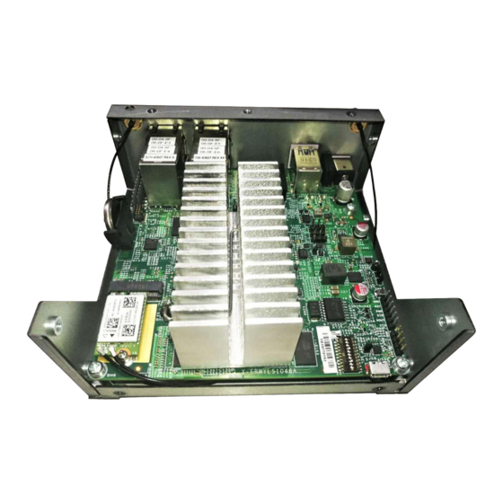
NXP Semiconductors Chassis and board pictures 4 Chassis and board pictures The figure below shows the front panel of the FRWY-LS1046A chassis. Console port Figure 1. FRWY-LS1046A chassis front panel The figure below shows the back panel of the FRWY-LS1046A chassis. - Page 4 NXP Semiconductors Chassis and board pictures J56, J57 Figure 3. Board top view - Connectors NOTE The Wi-Fi card (WNFQ-255ACN(BT)) shown in the above figure is only available in the FRWY-LS1046A-AC kit. It is not included in the FRWY-LS1046A-PA kit.
- Page 5 NXP Semiconductors Chassis and board pictures D509 D508 (reset button) D511 SW1 (DIP switch) Figure 4. Board top view - Jumpers, reset button, DIP switch, and LEDs The figure below shows the bottom-side view of the board, with two connectors and one LED highlighted.
-
Page 6: Reset Button
NXP Semiconductors Reset button D510 Figure 5. Board bottom view 5 Reset button The FRWY-LS1046A has a reset button for manually triggering a system reset. The reset button is highlighted in Figure 4. on page 5. The table below describes the reset button. -
Page 7: Connectors
NXP Semiconductors Connectors 6 Connectors Connectors are onboard devices that allow to connect external devices to the board. Figure 3. on page 4 and Figure 5. on page 6 show FRWY-LS1046A connectors. The table below describes the connectors. Table 4. FRWY-LS1046A connectors... -
Page 8: Jumpers
NXP Semiconductors Jumpers Table 4. FRWY-LS1046A connectors (continued) Part Connector type Description Typical connection identifier 1x3 connector I2C4 header I2C4 expansion header for remote access 2x10 connector GPIO header GPIO expansion header for remote access 1. It is placed on the bottom side of the PCB. -
Page 9: Leds
NXP Semiconductors LEDs • "ON" setting corresponds to 1 • "OFF" setting corresponds to 0 The DIP switch is highlighted in Figure 4. on page 5. The table below describes SW1 settings. Table 6. SW1 settings Switch Supported function Settings... -
Page 10: Getting Started With Frwy-Ls1046A
NXP Semiconductors Getting started with FRWY-LS1046A Table 7. FRWY-LS1046A LEDs (continued) Reference LED color LED name Description (when LED is ON) designator D509 Green 4_GRN_LED Four stacked LEDs to indicate: • Power status • System readyness • PROG_SFP fuse programming power enable 1. - Page 11 NXP Semiconductors Getting started with FRWY-LS1046A Table 8. Prerequisites (continued) Item Purpose / required action Tera Term (serial terminal emulator) To configure serial connection and to see console prints. Download and install it on the host computer from Internet. CodeWarrior Development Studio for To debug and control the board.
- Page 12 NXP Semiconductors Getting started with FRWY-LS1046A 8. Optionally, connect the CodeWarrior TAP to the board by performing the following steps: NOTE Follow the instructions included with the CodeWarrior package to set up the environment and host attachment, such as USB and Ethernet.
-
Page 13: Troubleshooting
NXP Semiconductors Troubleshooting PCIe0: pcie@3400000 disabled PCIe1: pcie@3500000 Root Complex: x1 gen1 PCIe2: pcie@3600000 Root Complex: x1 gen1 e1000: 68:05:ca:1c:02:c4 FM1@DTSEC1, FM1@DTSEC5, FM1@DTSEC6, FM1@DTSEC10, e1000#0 Hit any key to stop autoboot: => NOTE The above U-Boot log is an example log; the actual U-Boot log may vary slightly depending on the BSP version available on the board. - Page 14 How To Reach Us Information in this document is provided solely to enable system and software implementers to use NXP products. There are no express or implied copyright licenses granted hereunder to Home Page: design or fabricate any integrated circuits based on the information in this document. NXP nxp.com reserves the right to make changes without further notice to any products herein.
Need help?
Do you have a question about the Layerscape LS1046A and is the answer not in the manual?
Questions and answers