
Summary of Contents for Nuocai NC-DX0406
- Page 1 NC-DX0406(2018) User Manual NC-DX0406(2018 ) http://wap.happycolor.com.cn Guangzhou Nuocai Digital Products Co.,Ltd...
- Page 2 1. Warning: Please read this description carefully before using the machine 1.1. Machine should not be used by children or the disabled.If needed,please under the supervision 1.2. Please use original supplier’s spare parts and ink under instruction 1.3. Make sure the power voltage is same as power cable and machine which shown on the Nameplate 1.4.
- Page 3 1.20. Make sure machine is normally grounded 1.21. Do not use the machine in thunderstorm day,avoid lightning strikes 1.22. If your ink is not come from Nocai,after sale service will not be provide...
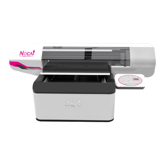
- Page 4 Machine recognition-Graphics Analysis 2.1 Machine Front View Printing table:Put the printing materials, the maximum length is 61cm,and Maximum width is 50cm,the maximum printing size is 60*40cm,template can be made to improve working efficiency. ② Panel control pane:Adjust and set up machine’s operation and internal parameter. ③...
- Page 5 2.2 Machine Back View ① Machine switch: Switch button. ② Power charger: Connect power box to supply power for printer. ③ Platform motor: Control platform to move the motor. ④ Platform motor driven wheel: Platform motor energy transmission,driven by drive wheel. ⑤...
- Page 6 2.3 Machine Capping System View ① Wiper sensor: Locate the wiper original position. ② Wiper: Clean the surface of the head after automatic cleaning. ③ Cap top: Suck ink,clean and protect the head. ④ Ink pump: Ink sucking, the left one is color ink pump, the right one is white ink pump. Speed can be adjusted at the back of pump.
- Page 7 2.4 Panel board View ① Bridge up button: Raise the bridge. ② Bridge down button: Down the bridge. ③ Carriage left button: Make the carriage move to the left side. ④ Carriage right button: Make the carriage move to the right side. ⑤...
- Page 8 2.5 Cart View ① Print head: Output the ink,head condition directly affect printing quality ② Big UV lamp: Dry the white and color ink ③ Damper: Guarantee the continuous supply of ink and filter impurities ④ Machine connection,data transmission and ink jet system ⑤...
- Page 9 2.6 Carriage Beam View ① Belt tension screw: Adjust screw tension can tension the belt ② Encoder strip: Provide accurate printing size for machine ③ Original position sheet: An sheet of original sensor ④ Carriage lock sheet: Shut down or during transportation lock the carriage ⑤...
- Page 10 2.7 Machine Right Side View ① UP limit sensor: Machine bridge up maximum ② Down limit sensor: Machine bridge down maximum ③ Up and down siding roof metal sheet: Use roof sheet metal to avoid the bridge move down to the limit when the down limit sensor is broken ④...
- Page 11 2.8 Ink Tank View ① Low ink alarming button: When the ink is low,the light will shinny to warn customer to add the ink ② White ink stirring button: To stir the white ink to let it smoothly flow ③ Ink tank cap: Protect the ink tank ④...
- Page 12 3. Fill ink into the ink tank According the picture instruction below, add the corresponding ink to ink tank by the indication of the color mark. The ink tank switch is open horizontally and closed vertically. Open Open Open When adding ink,in order to prevent the ink from leaking out of the machine cover,protective measures are required: The ink tank mouth can be wrapped with the tissues.After finishing adding the ink, ink tank should not be tightened to help ink flows smoothly.
- Page 13 Secondly, click“clean”, thirdly, click “Test”to print a nozzle check picture. If there is a lack of the lines, continue to click “clean”to clean the head.Once the nozzle check picture is good enough, then the ink installation process is complete. Nozzle check: a lack of the lines, machine need to continually clean automatically Nozzle check : lines are ok.
- Page 14 4.1.1 Find the “DVD driver”icon, then double click the icon to open it, then copy all the documents from the CD to the computer, then run the program “Autorun.exe”. 4.1.2 There is a pop-up dialog box, there choose the language that you want for your software 4.1.3 Click “Next”to continue the installation 4.1.4 Accept the clause and click “next”.
- Page 15 4.1.5 Select the disk where you want to install the software, then proceed to the “next” . 4.1.6 Choose the main programs that are needed to be installed and proceed to the “next” . There is a pop-up dialog box, then proceed to the “next” . 4.1.7 4.1.8 During the installation, the bellow dialog box will pop up, input the Activation code in it.
- Page 16 After inputting the Activation code,proceed to the “next” 4.1.9 Then Another dialog box will pop up, as bellow: In this step, please kindly enter the prompt website to activate first. 4.1.10 Enter the link: http://www.saicloud.com/...
- Page 17 Exit the linked website,return back to the dialog box, proceed to the “next” step according the instruction. ( Note: These steps will be available for the first time activation. 4.1.11 If there is no more instructions, it is the page of“Authorization success”.
- Page 18 4.1.12 Click “Finish”, it will be prompted: the security key is required. Please insert the U disk inside the CD box to the computer, and the computer will read automatically. The pop-up dialog shows that the installation is complete. 4.1.13 There are two icons on the desktop and double click “pp” icon to open the software. 4.1.14 D ouble click “pp”...
- Page 19 4.2 Photoprint connection setup 4.2.1 Close the Photopint software after installation, then copy the “HTPrintAPI0406” file into the photoprint file, as below shows. Open the Photoprint sign by mouse right button, choose “Properties” item to open it, then “Open file location”.
- Page 20 Then paste the HTPrintAPI0406 into the photoprint file, replace the old HTP file. P Atool driver installation 4.2.1 Set up the IP of the machine to connect the printer. Open the “Network and Sharing center” page and find the local connection, open the local connection and open the “Properties”, open the “Internet Protocol Version 4(TCP/IPv4).
- Page 21 Then set up the IP address as “192.168.1.188”, the subnet mask:255.255.255.0 will show accordingly. Then press OK to exit. 4.2.3 Use Add software to help the P Atool connection. Find the “Add ARP Table V1.0NU-20141206” in the Driver CD, and open it, “Run as administrator”. Then enter the next page.
- Page 22 Then press “Add”, then “Exit”. 4.3 P Atool driver installation and setup Connect the computer and printer by network cable which we offer, and open the Nuocai driver CD, the open the P Atools, it’ll show the below page.
- Page 23 Setup the printer and local IP. Printer IP i s 192.168.1.25, local IP is 192.168.1.188. If both IP are not correct, please press “apply” to adjust it.Then press “Connect” to connect the computer. Enter “advanced setup”, setting as below:...
- Page 24 Enter “advanced Alignment” page, and enter the step align number into the below item, for all the close, low, mid, high Eclosion version, “2020” is the average number.(Please kindly note that there has the stepping number printed on the paper which we put on the plate table, please enter the number accordingly).
-
Page 25: Print Setting
4.4 Print setting: 1. Dir: There are three options of the printing direction, R to L & L to R are one way printing, with better quality, yet slow printing speed; Bidi direction is with double printing speed, yet lower printing quality. - Page 26 5.2 Step Align: Adjust the Y axis direction print size. Usually, we'll adjust before shipping the printer out and will print the Step align number on the paper which put on the printer plate, just click the driver “ Advanced Alignment”, Then enter this page. Then on the basis of enclosion “...
- Page 27 5.4 Hidi alignment: Do this Hidi alignment when use the Bidi. For each different print height, need to do the Hidi alignment when choose to print Hidi direction version. 5.5 Alignment instruction:...
- Page 28 6 Photoprint setup: 1. Job: Choose the file that need to print; 2. Send: Send the file to the printer for printing; 3. Abort: Stop the printing job; 4. Delete: Delete the file in the photoprint page; Double click the imported picture then you can do some set up,interface picture is as follows 1.
- Page 29 2. Job size: Size of the printing file; 3. Position: The position to the start printing point on the plate table; 4. Copies: Choose how many file wanna repeat and the distance between each file; File setup: “F” to choose reverse printing or normal printing. Humanoid icons use to choose the direction of the printing file.
-
Page 30: Printer Options
1.Output file: Choose the correct ICC profile which we offer in the driver CD, then the below items will show accordingly; 2.Ignore overprint: When choose to print spot color version, don’t choose this item. Printer options: Inside the options,option 1 and option 2 click default,option 3 and option 4 drop down options: None means print only color without white Spot color means print white ink in some special parts not the whole file(More detail please check teaching video inside the Nocai CD) - Page 31 Paste & cut option: The picture size can be adjusted by using mouse.Click enter after setting or set up Default value save.Picture is as follows: Then enter into driver(ATool) to set up the color accounting certain printing requirement and click save after setting.picture is as follows:...
- Page 32 Before printing, when put the printing materials on the plate table, should adjust the print height between the print head and the printing material, 2-3mm. (Adjust by eye) 7.Common printing position(take phone case as an example) 1.Drag the already-done picture(with spot color) into software.Picture is as follows: 2.
- Page 33 3. Inside the printer options,select Spot_1 and Spot_2(Spot_1 stands for white ink of the spot color,Spot_2 stands for white ink of the spot color).Then click “Send”.Picture is as follows: 4. Before printing, when put the printing materials on the plate table, should adjust the print height between the print head and the printing material, 2-3mm.
- Page 34 5.After sending.phone case can be printed directly,when it finished printing,picture is like this...
-
Page 35: Machine Maintenance
8 .Machine maintenance: 1. Print head maintenance: ① There is a small board inside the print head, for which connect with the printhead cable. Please keep the connection port dry, if there's any liquid on the conection port,turn off the machine immediately and and take off the cable to clean it. - Page 36 2. Outer side cover maintenance: Keep the cover clean and clean the dust or waste ink by alcohol on time to avoid the corrosion 9. Solution: 9.1: Nozzle test issue: (1) . Normal nozzle test normal normal normal normal normal norma (2).
- Page 37 3.Clean the print head by using syringe with uv cleaner to make sure the nozzle holes are not blocked. Mark: The problem is usually caused by damper and nozzle hole blocking. (4) Line break on almost all the nozzle holes line break line break normal...
- Page 38 (6)No ink at all on nozzle test Solution: 1.Disconnect and reconnect the print head cable, check if the print head cable has problem or not and if the print head cable insert well or not. 2.Check if there’s any ink or liquid in the cable connection port, if so, clean it and test again. 3.Replace the print head board.
- Page 39 Solution: 1.Check the print height between the print head and the printing material, it should be 2-3mm. 2.Check the temperature, should be 15℃ to 30℃. 3.Check if the damper can suck ink correct or not. 4.Stir the ink which has the floating problem, and suck the damper of this ink out about 10ml, then clean the print head.
- Page 40 As the picture shows above, loose the screws on the cap top and can move the position of the cap top 6. Adjust the print head on vertical direction. Loose the screws on the print head to adjust it. Mark: The problem might cause by the new print head and cap top installation, then the position of the print head and cap top is not OK.
-
Page 41: Error Code
3.3 Clean the encoder strip by alcohol if there is any ink, dust, oil or other dirty on it. 3.4 Check if the encoder strip is in the middle of the encoder strip sensor. 3.5 Check if the encoder strip is in the bars or not. 3.6 Replace the print head board(barely has this problem). - Page 42 Error 8: Motor is less powerful, need to adjust the dail up of the motor; Error 9: Motor is more powerful, need to adjust the dail up of the motor; Error 10: Print head board and mainboard are not match, check which one is wrong; Error 11: Default the machine;...
- Page 43 UV lamp cable 2. Check if the uv lamp power box works or not. UV lamp power box...
- Page 44 3 .Please check if there’s 24V voltage output from the J26(varnish lamp) & J27(uv ink lamp), if no, replace the mainboard. 4 . Replace the uv lamp. 9.11 UV ink not dry. 1. All the products on the table not dry: Check the uv lamp, refer to the below uv lamp doesn’t work solution. 2.
- Page 45 J1: Y axis motor JP2: Mainboard Fan J3: Ink pump J4: White ink circulation J6: Wiper limited sensor J7: Front side limited sensor J8: Back side limited sensor J10: Front board grey cable J11: Stepping motor signal cable J12: X axis motor signal cable J23: Original position limited sensor J24: Ink tank board J25: Upper limited sensor J26: Down side limited sensor...
- Page 46 12. Color array of XP600 print head KCMWYW...
Need help?
Do you have a question about the NC-DX0406 and is the answer not in the manual?
Questions and answers