
Related Manuals for Keysight 4000 X-Series


Summary of Contents for Keysight 4000 X-Series
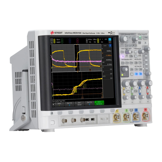
- Page 1 Keysight 4000 X-Series Oscilloscopes Lab guide and tutorial for making advanced oscilloscope measurements using an Keysight 4000 X-Series oscilloscope with the DSOXEDK training kit. Advanced Training Guide...
- Page 2 (including elec- contract clause. Use, duplication or disclo- tronic storage and retrieval or translation Ed ition sure of Software is subject to Keysight Tech- into a foreign language) without prior agree- nologies’ standard commercial license ment and written consent from Keysight...
-
Page 3: Table Of Contents
Lab #14: Triggering on Logic Patterns using the MSO’s Digital Channels / 74 4 Serial Bus Decoding & Triggering, Search & Navigation, and Segmented Acquisition Labs Lab #15: Decoding, Triggering, and Searching on I C Serial Bus Signals / 80 4000 X-Series Oscilloscopes Advanced Training Guide... - Page 4 Step 1: Determine fastest actual edge speeds / 160 Step 2: Calculate f knee / 160 Step 3: Calculate scope bandwidth / 161 Example / 161 Digital Clock Measurement Comparisons / 163 C Related Keysight Literature Index 4000 X-Series Oscilloscopes Advanced Training Guide...
-
Page 5: Getting Started
Keysight 4000 X-Series Oscilloscopes Advanced Training Guide 1 Getting Started Lab Guide—At a Glance / 6 Front Panel Overview / 8... -
Page 6: Lab Guide-At A Glance
Keysight Technologies InfiniiVision 4000 X-Series oscilloscopes (DSO and MSO models) that are licensed with the Oscilloscope Education Training Kit (DSOXEDK). When licensed with this training kit, 4000 X-Series oscilloscopes are able to generate a broad range of built-in training signals. - Page 7 Getting Started If you not familiar with the Keysight InfiniiVision 4000 X-Series oscilloscope, first look over the main sections of the front panel as illustrated on the following pages, and then begin with Chapter 2, “Oscilloscope Familiarization Labs,” starting on page 13.
-
Page 8: Front Panel Overview
• The [Analyze] key sets trigger levels, measurement threshold levels, video trigger auto setup and display, or the mask testing application options. • The [Acquire] key on the front panel lets you set the oscilloscope data acquisition modes. 4000 X-Series Oscilloscopes Advanced Training Guide... -
Page 9: Horizontal Controls
(zoom) key to quickly turn on the zoom mode. This split-screen mode shows the big picture on top and an expanded view on the bottom. Turn the large timebase knob counter-clockwise to make the window on top larger. 4000 X-Series Oscilloscopes Advanced Training Guide... -
Page 10: Vertical Controls
(waveform). Auto trigger mode is useful when unsure of the exact waveform because forced acquisitions are displayed, making it easy to better configure the oscilloscope’s settings and trigger level. 4000 X-Series Oscilloscopes Advanced Training Guide... -
Page 11: Tools Controls
“Quick Action” key function settings. • Press the [Quick Action] key to perform one of the quick action functions that can be mapped to this key. • Press [WaveGen1] or [WaveGen2] to use the Arbitrary Waveform Generators. 4000 X-Series Oscilloscopes Advanced Training Guide... - Page 12 Getting Started 4000 X-Series Oscilloscopes Advanced Training Guide...
-
Page 13: Oscilloscope Familiarization Labs
Keysight 4000 X-Series Oscilloscopes Advanced Training Guide 2 Oscilloscope Familiarization Labs Lab #1: Using Cursors and Automatic Parametric Measurements / 14 Lab #2: Using Zoom Display to Perform Gated Measurements / 21 Lab #3: Using Waveform Math / 25 Lab #4: Using Peak Detect Acquisition Mode / 29... -
Page 14: Lab #1: Using Cursors And Automatic Parametric Measurements
Push the trigger level knob to automatically set the trigger level at approximately 50%. Set the scope’s timebase to 500.0 ns/d iv. Figure 1 Oscilloscope setup to capture and display a repetitive digital pulse with ringing and overshoot. 4000 X-Series Oscilloscopes Advanced Training Guide... - Page 15 Select Y2 on the right of the display (#2 voltage marker) and move it vertically such that it intersects with the positive peak of the pulse. 4000 X-Series Oscilloscopes Advanced Training Guide...
- Page 16 Because this scope is able to show up to four continuously updated measurements, let’s add more measurements. Press the Type softkey; then select Maximum. Notice the level indicator that shows where this measurement is being performed. 4000 X-Series Oscilloscopes Advanced Training Guide...
- Page 17 Frequency, Vp-p, Vmax, and Vmin. Let’s now perform four different measurements. Set the scope’s timebase to 200.0 ns/d iv. Expanding on the pulse will provide us with increased measurement resolution. Now select to measure Top, Base, Rise Time, and Fall Time. 4000 X-Series Oscilloscopes Advanced Training Guide...
- Page 18 The scope’s default threshold levels for these measurements are the 10% and 90% levels relative to Vbase and Vtop. But many of today’s higher speed devices have specified rise and fall times relative to 20% 4000 X-Series Oscilloscopes Advanced Training Guide...
- Page 19 40 ns. Let’s now make one more measurement before completing this lab. But this time let’s perform a more comprehensive set of measurements on this waveform. 4000 X-Series Oscilloscopes Advanced Training Guide...
- Page 20 Figure 7. Note that this set of measurements is not continuously updated, and if you press any front panel or softkey, the display of these measurements will disappear. 4000 X-Series Oscilloscopes Advanced Training Guide...
-
Page 21: Lab #2: Using Zoom Display To Perform Gated Measurements
Trigger Holdoff. You can learn more about Trigger Holdoff during “Lab #7: Triggering on a Digital Burst using Trigger Holdoff" on page 44. 4000 X-Series Oscilloscopes Advanced Training Guide... - Page 22 Press the Clear Meas softkey; then press the Clear All softkey. Press the Type softkey; then press the + Wid th measurement. Either press it again or press the Add Measurement softkey to select this measurement. 4000 X-Series Oscilloscopes Advanced Training Guide...
- Page 23 Set the horizontal position/delay to 950.0 ns in order to window-in on the 3rd pulse. When the “zoom” display is turned on, the horizontal controls (s/div and position) control the zoomed (or expanded) timebase settings. 4000 X-Series Oscilloscopes Advanced Training Guide...
- Page 24 You should now see on your scope’s display an expansion of just the 3rd pulse in this burst in the lower portion of the display as should in Figure 10. And the + Width measurement should be measuring the positive pulse width of just the 3rd pulse. 4000 X-Series Oscilloscopes Advanced Training Guide...
-
Page 25: Lab #3: Using Waveform Math
Press the [Math] front panel key (right-hand side of front panel). Press the Operator softkey and select "-". Change the Math voltage scale to 500mV/div using the knob above the [Math] front panel key. 4000 X-Series Oscilloscopes Advanced Training Guide... - Page 26 Press [Default Setup]. Press [Help]; then press the Training Signals softkey. Select the Clock with Infrequent Glitch signal and press the Output softkey to turn it on. Set channel-1’s V/div setting to 500 mV/d iv. 4000 X-Series Oscilloscopes Advanced Training Guide...
- Page 27 (signal’s repetitive frequency), plus its odd harmonics (3rd, 5th, 7th, etc.). Note that non-ideal square waves will also include lower-level even harmonics. Let’s now verify the frequencies of the fundamental and odd harmonics. 4000 X-Series Oscilloscopes Advanced Training Guide...
- Page 28 But the measurement requires that the input signal be repetitive. The “frequency” measurement measures the period of just one cycle of the signal, and then computes the frequency by taking the reciprocal. 4000 X-Series Oscilloscopes Advanced Training Guide...
-
Page 29: Lab #4: Using Peak Detect Acquisition Mode
Set channel-1’s V/div setting to 500.0 mV/d iv. Set the scope’s timebase to 10.00 ms/d iv. Press the [Intensity] button (under the Entry knob); then set the waveform trace intensity to 100% using the Entry knob or on-screen slider. 4000 X-Series Oscilloscopes Advanced Training Guide... - Page 30 The amplitude of these glitches is actually very stable. The problem is that the scope has reduced its sample rate (note the sample rate shown under the Keysight logo on the scope’s display) and the scope is now intermittently capturing the narrow glitches. The scope is under-sampling the narrow glitches.
- Page 31 And this is an important criterion of the Nyquist Sampling theorem. So for this particular measurement application, using the Peak Detect mode is a good choice. But for other measurement applications, Peak Detect may not be the appropriate acquisition mode. 4000 X-Series Oscilloscopes Advanced Training Guide...
- Page 32 Oscilloscope Familiarization Labs To learn more about oscilloscope real-time sampling, refer to Keysight’s Application Note titled, “Evaluating Oscilloscope Sample Rates vs Sampling Fidelity” listed in “Related Keysight Literature" on page 167. 4000 X-Series Oscilloscopes Advanced Training Guide...
-
Page 33: Lab #5: Using Segmented Memory Acquisition Mode
Segmented Memory acquisition mode is another solution to optimize memory depth and sample rate; especially when attempting to capture multiple low duty cycle type signals. Keysight 4000 X-Series Oscilloscopes come with segmented memory as a standard option. Let’s now attempt to capture and display a simulated low duty cycle radar burst. - Page 34 You should see a single burst of sine waves similar to what is shown in Figure Let’s now rescale the timebase in an attempt to capture several of these bursts. Set the scope’s timebase to 10.000 ms/d iv. 4000 X-Series Oscilloscopes Advanced Training Guide...
- Page 35 Let’s now zoom-in and take a closer look at this under-sampled data. Press [Run/Stop] to stop repetitive acquisitions ([Run/Stop] key will turn red). Now set the scope’s timebase to 200.0 ns/d iv. 4000 X-Series Oscilloscopes Advanced Training Guide...
- Page 36 Segmented softkey to open the Segmented Memory settings. Set # of Segs = 500. Now press the Segmented softkey to turn on this mode of acquisition. The scope should have just captured 500 consecutive occurrences of this burst. Let’s review them. 4000 X-Series Oscilloscopes Advanced Training Guide...
- Page 37 (or segments) of a signal (a short sine wave burst in this case). The scope does not capture unimportant signal idle-time between each burst. Segmented Memory acquisition can also be a very 4000 X-Series Oscilloscopes Advanced Training Guide...
- Page 38 Oscilloscope Familiarization Labs useful tool for capturing multiple serial packets of digital data, which will be demonstrated in Chapter 4, “Serial Bus Decoding & Triggering, Search & Navigation, and Segmented Acquisition Labs,” starting on page 79. 4000 X-Series Oscilloscopes Advanced Training Guide...
-
Page 39: Lab #6: Using Mask Test
Push the Trigger Level knob to set the trigger level at 50%. Set the timebase to 20 ns/d iv. Set the waveform intensity to 100% by first pressing the [Intensity] button; then turn the Entry knob. 4000 X-Series Oscilloscopes Advanced Training Guide... - Page 40 Let’s now use the scope’s Mask Test capability to analyze this glitch. Press [Analyze]. Press Features Mask two times to turn on mask testing. Press Automask. Press Create Mask to automatically create a pass/fail mask around this waveform. 4000 X-Series Oscilloscopes Advanced Training Guide...
- Page 41 Press Statistics. Press Reset Statistics to clear the statistics from the previous test. Press the (Back) key. Back Press Setup. Press On Error – Stop two times. Press [Run/Stop] to begin a new “Stop-on-Error” test. 4000 X-Series Oscilloscopes Advanced Training Guide...
- Page 42 USB memory device. These types of imported masks can be easily created within a standard text editor, such as Notepad on your PC. 4000 X-Series Oscilloscopes Advanced Training Guide...
-
Page 43: Advanced Triggering, Search & Navigation, And Segmented Acquisition Labs
Keysight 4000 X-Series Oscilloscopes Advanced Training Guide 3 Advanced Triggering, Search & Navigation, and Segmented Acquisition Labs Lab #7: Triggering on a Digital Burst using Trigger Holdoff / 44 Lab #8: Triggering on Unique Pulses and Glitches using “Pulse-width” Trigger / 48 Lab #9: Triggering on the Nth Pulse within a Burst using “Nth Edge Burst”... -
Page 44: Lab #7: Triggering On A Digital Burst Using Trigger Holdoff
Push the Trigger Level knob to automatically set the trigger level to approximately 50%. Set the scope’s timebase to 20.00 µs/d iv. Figure 22 Attempting to view a burst of pulses while using the scope’s default trigger setup conditions. 4000 X-Series Oscilloscopes Advanced Training Guide... - Page 45 (high level), and then it repeats. If you press [Single] several times, you should observe that the trigger event (rising edge closest to center-screen) for each acquisition is almost always a different pulse within the burst. 4000 X-Series Oscilloscopes Advanced Training Guide...
- Page 46 Tap the Holdoff softkey twice to bring up the keypad; set to 45.000 µs. Trigger Point Holdoff Time Next Valid Trigger Event Figure 24 Using the scope’s trigger holdoff feature to synchronize on a burst of pulses. 4000 X-Series Oscilloscopes Advanced Training Guide...
- Page 47 2nd, 3rd, 4th, etc., crossings, and then re-arms triggering after the end of the burst, but before the beginning of the next burst, which is during the signal’s “idle-time”. The next valid trigger event will again be the 1st edge crossing on the next burst. 4000 X-Series Oscilloscopes Advanced Training Guide...
-
Page 48: Lab #8: Triggering On Unique Pulses And Glitches Using "Pulse-Width" Trigger
Set the trigger level to +1.00 V (~1 division above bottom of waveform). Set the scope’s timebase to 2.000 µs/d iv. Figure 25 Capturing a digital burst using the scope’s default Edge triggering mode. 4000 X-Series Oscilloscopes Advanced Training Guide... - Page 49 Tap the “ < 30 ns ” softkey; then set the time to < 350 ns using the keypad. Tap the “ > 20 ns ” softkey; then set the time to > 250 ns using the keypad. Set the scope’s timebase to 500.0 ns/d iv. 4000 X-Series Oscilloscopes Advanced Training Guide...
- Page 50 Pulse Width triggering mode to trigger on “unknown” or “unwanted” glitches. Let’s do it. Tap the “ < > >< ” softkey; then select the “<” time qualifier. Tap the < 30 ns softkey; then set the time to < 50 ns. 4000 X-Series Oscilloscopes Advanced Training Guide...
- Page 51 Tap the Segmented softkey to begin a Segmented Memory acquisition. Tap the Current Segment softkey; then turn the Entry knob to review all 500 captured segments. Or, tap it a second time to set a specific value. 4000 X-Series Oscilloscopes Advanced Training Guide...
- Page 52 But the scope does provide us with timing information about the time of each segment relative to the first captured segment. As you were reviewing each captured segment, you should have determined the glitch occurs every on 40th occurrence of the burst. 4000 X-Series Oscilloscopes Advanced Training Guide...
-
Page 53: Lab #9: Triggering On The Nth Pulse Within A Burst Using "Nth Edge Burst" Trigger
Set the trigger level to +1.00 V (~1 division above bottom of waveform). Set the scope’s timebase to 500 ns/d iv. Figure 29 Capturing a digital burst using the scope’s default Edge triggering mode. 4000 X-Series Oscilloscopes Advanced Training Guide... - Page 54 To trigger on other edges within this burst, vary the Edge count setting between 1 and 7. 4000 X-Series Oscilloscopes Advanced Training Guide...
-
Page 55: Lab #10: Triggering On And Searching For Edge Speed Violations
Set channel-1 offset/position to approximately 1.6 V to center the waveform on-screen. Push the trigger level knob to automatically set the trigger level to approximately 50%. Set the scope’s timebase to 100.0 ns/d iv. 4000 X-Series Oscilloscopes Advanced Training Guide... - Page 56 Press [Meas]; then tap the Type softkey. Select the Rise Time measurement; Once on, tap Statistics and then Display On. 4000 X-Series Oscilloscopes Advanced Training Guide...
- Page 57 This might help us isolate what the root cause might be that is causing these occasional violations. Uniquely triggering on edge speed violation signals can be accomplished on Keysight’s 4000 X-Series oscilloscopes using the Rise/Fall Time triggering mode. Press the [Trigger] front panel key and select the Rise/Fall Time trigger type.
- Page 58 100 ns as shown in Figure 33. In addition to triggering on Rise/Fall Time violation edges, the Keysight 4000 X-Series oscilloscopes can also perform Search & Navigation to find multiple edge speed violation conditions, regardless of the specific trigger setup condition.
- Page 59 Push the horizontal position/delay knob to re-position the trigger point back to center-screen. Set the scope’s timebase to 100.0 ns/d iv. Press the [Run/Stop] front panel to begin repetitive acquisition again. Press the [Acquire] front panel key. 4000 X-Series Oscilloscopes Advanced Training Guide...
- Page 60 In this example, we have selectively captured 500 occurrences of this signal that has a rise time violation for a total acquisition time of nearly 100 ms. 4000 X-Series Oscilloscopes Advanced Training Guide...
-
Page 61: Lab #11: Triggering On And Searching For Runt Pulses
Set channel-1 offset/position to approximately 1.6 V to center the waveform on-screen. Push the trigger level knob to automatically set the trigger level to approximately 50%. Set the scope’s timebase to 100.0 ns/d iv. 4000 X-Series Oscilloscopes Advanced Training Guide... - Page 62 1 division above the bottom of the waveform. Tap the Level Select softkey to select High; then turn the Trigger Level knob to set the upper trigger level threshold to be approximately 1 division below the top of the waveform. 4000 X-Series Oscilloscopes Advanced Training Guide...
- Page 63 You can also change the polarity of the runt triggering to either “positive runts only”, “negative runts only”, or “either polarity runts” using the appropriate softkey selection. Note that the Keysight 4000 X-Series oscilloscopes can also trigger on runt pulses that meet a specific time qualification.
- Page 64 100 ns wide near center-screen. In addition to triggering on runt pulse conditions, the Keysight 4000 X-Series oscilloscopes can also perform Search & Navigation to find multiple runt pulse conditions, regardless of the specific trigger setup condition.
- Page 65 Push the horizontal position/delay knob to re-position the trigger point back to center-screen. Set the scope’s timebase to 100.0 ns/d iv. Press the [Run/Stop] front panel to begin repetitive acquisition again. Press the [Trigger] front panel key. 4000 X-Series Oscilloscopes Advanced Training Guide...
- Page 66 In this example, we have selectively captured 500 occurrences of positive and negative runts of any width for a total acquisition time of more than 20 ms as shown in Figure 4000 X-Series Oscilloscopes Advanced Training Guide...
-
Page 67: Lab #12: Triggering On Setup & Hold Time Violations
(yellow trace) is a clock signal, while the channel-2 waveform (green trace) represents a random data signal presented in an eye-diagram format. When clocking data into a memory device, if the data signal is going to 4000 X-Series Oscilloscopes Advanced Training Guide... - Page 68 Let’s do it. Press the [Trigger] front panel key. Select the Setup & Hold trigger type. Double-tap the < Setup softkey and enter 25 ns. 4000 X-Series Oscilloscopes Advanced Training Guide...
- Page 69 Tap the Segmented softkey to begin a Segmented Memory acquisition. Tap the Current Segment softkey; then turn the Entry knob to review all 500 captured segments. Set the Current Segment to 500 and note the time-tag of the last captured segment. 4000 X-Series Oscilloscopes Advanced Training Guide...
- Page 70 In this example, we have selectively captured 500 consecutive occurrences of a setup time violation for a total acquisition time of approximately 20 ms as shown in Figure 4000 X-Series Oscilloscopes Advanced Training Guide...
-
Page 71: Lab #13: Triggering On A Qualified Burst Using "Edge Then Edge" Trigger
Set channel-2 to 1.0 V/d iv. Set channel-2 offset/position to approximately 2.0 V. Push the trigger level knob to automatically set the trigger level on both channels to approximately 50%. Set the scope’s timebase to 1.0 µs/d iv. 4000 X-Series Oscilloscopes Advanced Training Guide... - Page 72 Nth occurrence of one of the wider digital pulses. Press the [Trigger] front panel key; then select Edge then Edge. Double-tap the Delay softkey; then enter 2.0 µs. Double-tap the Nth Edge B softkey and enter 3. 4000 X-Series Oscilloscopes Advanced Training Guide...
- Page 73 Your scope’s triggering should now be synchronized on the 3rd digital pulse on channel-2 after qualifying on the channel-1 pulse, and after delaying past the higher frequency analog burst as shown in Figure 4000 X-Series Oscilloscopes Advanced Training Guide...
-
Page 74: Lab #14: Triggering On Logic Patterns Using The Mso's Digital Channels
Set the scope’s timebase to 50.00 µs/d iv. Press the [Digital] front panel key (right side of scope) to turn on the digital channels of acquisition. Tap the Turn off D15-D8 softkey to turn off the upper 8 digital channels. 4000 X-Series Oscilloscopes Advanced Training Guide... - Page 75 DAC (positive peak of the stair-step sine wave). Press the [Trigger] front panel key; then select Pattern. Tap the Channel softkey; then select D7. 4000 X-Series Oscilloscopes Advanced Training Guide...
- Page 76 HEX value of the bus. Let’s now set up the scope to show the bus display mode. Press the [Digital] front panel key; then tap the Bus softkey. Double-tap the Bus softkey to enable the Bus1 bus display mode. Set the scope’s timebase to 20.00 µs/d iv. 4000 X-Series Oscilloscopes Advanced Training Guide...
- Page 77 Tap the Digit softkey; then select 1 using the Entry knob. Tap the Hex softkey; then select 1 using the Entry knob. Tap the Digit softkey; then select 0 using the Entry knob. Tap the Hex softkey; then select A using the Entry knob. 4000 X-Series Oscilloscopes Advanced Training Guide...
- Page 78 Advanced Triggering, Search & Navigation, and Segmented Acquisition Labs Figure 49 Triggering on pattern = 1A Your scope should now be triggering on 1A , which is coincident with the lowest output level of DAC, as shown in Figure 4000 X-Series Oscilloscopes Advanced Training Guide...
-
Page 79: Serial Bus Decoding & Triggering, Search & Navigation, And Segmented Acquisition Labs
Keysight 4000 X-Series Oscilloscopes Advanced Training Guide 4 Serial Bus Decoding & Triggering, Search & Navigation, and Segmented Acquisition Labs Lab #15: Decoding, Triggering, and Searching on I2C Serial Bus Signals / 80 Lab #16: Decoding, Triggering, and Searching on SPI Serial Bus Signals / 87... -
Page 80: Lab #15: Decoding, Triggering, And Searching On I 2 C Serial Bus Signals
Press the [2] front panel key to turn on channel-2. Set channel-2 to 1.00 V/d iv. Set channel-2’s offset/position to +3.50 V. Push the trigger level knob to set the trigger level to approximately 50%. Set the scope’s timebase to 500.0 µs/d iv. 4000 X-Series Oscilloscopes Advanced Training Guide... - Page 81 Back previous menu. Tap the Addr Size softkey and verify that 7 Bit is selected. Tap the Lister softkey; then select Window and tap Hal f-Screen to show a list of Serial 1 (I2C). 4000 X-Series Oscilloscopes Advanced Training Guide...
- Page 82 Press the [Trigger] front panel key; then select Serial 1 (I C) using the Entry knob. Tap the Trigger: Start softkey; then select Frame(Start:Addr 7:Read:Ack:Data). Tap the Address softkey; then set to 0x29 using the Entry knob. 4000 X-Series Oscilloscopes Advanced Training Guide...
- Page 83 As you scroll through the data, note that waveforms “track”. This means that the frame that the arrow points to in the lister table corresponds to the waveforms that are positioned at center-screen. If you want to zoom in on a particular I C frame, 4000 X-Series Oscilloscopes Advanced Training Guide...
- Page 84 200 ms. Note that the number of “found” events is indicated near the bottom of the display. To automatically navigate to each frame with a “Missing Acknowledge”, press the front panel navigation keys near the timebase controls. 4000 X-Series Oscilloscopes Advanced Training Guide...
- Page 85 Tap the Current Segment softkey; then turn the Entry knob to review all 500 captured segments. Set the Current Segment to 500 and note the time-tag of the last captured segment. Figure 54 Using the scope’s Segmented Memory acquisition to selectively capture more I traffic. 4000 X-Series Oscilloscopes Advanced Training Guide...
- Page 86 Figure 54. Note that we can also view the decoded I C data in the “lister” format, and we can also perform Search & Navigation on the segments. 4000 X-Series Oscilloscopes Advanced Training Guide...
-
Page 87: Lab #16: Decoding, Triggering, And Searching On Spi Serial Bus Signals
Tap the Turn off D15-D9 softkey to turn off the upper 8 digital channels. Tap the Channel softkey. Double tap on D9 to enable digital channel 9. Repeat Step #9 to also turn on D8, D7, and D6. Set the scope’s timebase to 200.0 µs/d iv. 4000 X-Series Oscilloscopes Advanced Training Guide... - Page 88 Tap the Signals softkey. Tap the Clock softkey twice to open the menu; then double-tap D7 to set it as as the clock source. Press the (Back) front panel button to return to the previous menu. Back 4000 X-Series Oscilloscopes Advanced Training Guide...
- Page 89 Press the [Trigger] front panel key; then select Serial 1 (SPI). Tap the Trigger Setup softkey. Tap the Bit softkey and enter 0 in the keypad. Tap the 0 1 X softkey to select 0 as the trigger logic condition for Bit 0 (MSB). 4000 X-Series Oscilloscopes Advanced Training Guide...
- Page 90 As you scroll through the data, note that waveforms “track”. This means that the frame that the arrow points to in the lister table corresponds to the waveforms that are positioned at center-screen. If you want to zoom in on a particular SPI frame of 4000 X-Series Oscilloscopes Advanced Training Guide...
- Page 91 The white triangles near the top of the waveform area mark the time location of each “found” occurrence of our search operation as shown in Figure 58. These frames are also marked in orange in the first/pointer column of the lister table. 4000 X-Series Oscilloscopes Advanced Training Guide...
- Page 92 Tap the Segmented softkey to begin a Segmented Memory acquisition. Tap the Current Segment softkey; then turn the Entry knob to review all 500 captured segments. Set the Current Segment to 500 and note the time-tag of the last captured segment. 4000 X-Series Oscilloscopes Advanced Training Guide...
- Page 93 In this example, we have selectively captured over 4 seconds of total acquisition time as shown in Figure 59. Note that we can also view the decoded SPI data in the “lister” format, and we can also perform Search & Navigation on the segments. 4000 X-Series Oscilloscopes Advanced Training Guide...
-
Page 94: Lab #17: Decoding, Triggering, And Searching On Rs232/Uart Serial Bus Signals
Set channel-2 to 1.00 V/d iv. Set channel-2’s offset/position to +2.3 V. Push the trigger level knob to automatically set the trigger level to approximately 50%. Set the scope’s timebase to 2.00 ms/d iv. 4000 X-Series Oscilloscopes Advanced Training Guide... - Page 95 Tap the Signals softkey and verify that Rx is defined as channel-1, and that Tx is defined as channel-2 (default conditions). Press the (Back) front panel button (above power switch) to return to the Back previous menu. Tap the Bus Config softkey. Tap the Parity softkey; then select Odd. 4000 X-Series Oscilloscopes Advanced Training Guide...
- Page 96 Press the [Trigger] front panel key; then select Serial 1 (UART/RS232). Tap the Trigger Setup softkey; then select Tx Data from the Trigger menu. Tap the Data softkey; then select 0x4D using the Entry knob. Set the scope’s timebase to 1.000 ms/d iv. 4000 X-Series Oscilloscopes Advanced Training Guide...
- Page 97 So let’s now perform an automatic search to find every occurrence of parity bit errors on both the Tx and Rx data lines. We will then automatically navigate to each of these occurrences. 4000 X-Series Oscilloscopes Advanced Training Guide...
- Page 98 Let’s now set up the scope to trigger exclusively on parity errors. But because these errors occur so infrequently, we will need to change the trigger mode from Auto to Normal to prevent auto triggering. 4000 X-Series Oscilloscopes Advanced Training Guide...
- Page 99 But to complete the rest of this lab your scope must be licensed with the Segmented Memory option. Press the [Acquire] front panel key. 4000 X-Series Oscilloscopes Advanced Training Guide...
- Page 100 RS232/UART serial data in the “lister” format, and we can also perform Search & Navigation on the segments. Let’s now view this decoded RS232/UART in a different numeric format to uncover a important Keysight marketing message. Press the [Serial] front panel key; then tap the Settings softkey Tap the Base softkey;...
- Page 101 Serial Bus Decoding & Triggering, Search & Navigation, and Segmented Acquisition Labs Figure 66 Decoded RS232/UART message indicating which oscilloscope vendor is #1 in the MSO market. 4000 X-Series Oscilloscopes Advanced Training Guide...
-
Page 102: Lab #18: Decoding, Triggering, And Searching On Can Serial Bus Signals
Set channel-1 to 500.0 mV/d iv. Set channel-1’s offset/position to +1.4 V. Push the trigger level knob to automatically set the trigger level to approximately 50%. Set the scope’s timebase to 100.0 µs/d iv. 4000 X-Series Oscilloscopes Advanced Training Guide... - Page 103 Tap the Signals softkey; then from the Signal menu, select CAN_L. With the Signals menu active, also verify that the input Source is defined as channel-1 and the baud rate is set to 125 kb/s (default conditions). 4000 X-Series Oscilloscopes Advanced Training Guide...
- Page 104 Select Serial 1 (CAN) from the Trigger Type menu. Tap Trigger on: SOF; then select Data Frame ID (~RTR). Tap the Bits softkey. Tap the Hex softkey; then select F using the Entry knob. 4000 X-Series Oscilloscopes Advanced Training Guide...
- Page 105 If you want to zoom in on a particular CAN frame of data, either push the Entry knob, or tap the Zoom to Selection softkey. Looking for infrequent errors in this long decoded record can be difficult. So let’s now perform 4000 X-Series Oscilloscopes Advanced Training Guide...
- Page 106 1 second. Note that the number of “found” events is indicated near the bottom of the display. To automatically navigate to each CAN error, press the front panel navigation keys. 4000 X-Series Oscilloscopes Advanced Training Guide...
- Page 107 Set the Current Segment to 100 and note the time-tag of the last captured segment. This can be done with the Entry knob, or double-tapping Current Seg and tapping Max on the keypad. 4000 X-Series Oscilloscopes Advanced Training Guide...
- Page 108 71. Note that we can also view the segmented decoded CAN serial data in the “lister” format, and we can also perform Search & Navigation operations on the captured segments. Press the [Serial] front panel key; then tap the Lister softkey. 4000 X-Series Oscilloscopes Advanced Training Guide...
- Page 109 Because we performed the Segmented Memory acquisition based on triggering on any “form” or flagged “error frame” condition (All Errors), our Lister display now shows that every captured frame contains some type of error as shown in Figure 4000 X-Series Oscilloscopes Advanced Training Guide...
-
Page 110: Lab #19: Decoding, Triggering, And Searching On Lin Serial Bus Signals
Set channel-1 to 500.0 mV/d iv. Set channel-1’s offset/position to +1.4 V. Push the trigger level knob to automatically set the trigger level to approximately 50%. Set the scope’s timebase to 1.00 ms/d iv. 4000 X-Series Oscilloscopes Advanced Training Guide... - Page 111 Tap the Mode I C softkey; then select the LIN serial decode mode. Tap the Signals softkey and then the Baud Rate softkey and verify that the Baud Rate is set to 19.2 kb/s. 4000 X-Series Oscilloscopes Advanced Training Guide...
- Page 112 Press the [Trigger] front panel key. Select Serial 1 (LIN) using the Trigger Type menu. Tap Trigger on: Sync; then select ID – Frame ID. Tap the Frame ID softkey; then set ID = 0x21 using the Entry knob. 4000 X-Series Oscilloscopes Advanced Training Guide...
- Page 113 Tap the Lister softkey; then select Hal f-Screen from the Window menu. Set the scope’s timebase to 200.00 ms/d iv. Press [Run/Stop] to stop repetitive acquisitions. Tap the Scroll Lister softkey; then turn the Entry knob to manually scroll through the lister table. 4000 X-Series Oscilloscopes Advanced Training Guide...
- Page 114 Your scope should have found and marked more than 15 occurrences of this search operation based on a total acquisition time of 2 seconds. Note that the 4000 X-Series Oscilloscopes Advanced Training Guide...
- Page 115 Tap the Current Segment softkey; then turn the Entry knob to review all 500 captured segments. Tap it again to pull up the keypad to manually enter a segment number. Set the Current Segment to 500 and note the time-tag of the last captured segment. 4000 X-Series Oscilloscopes Advanced Training Guide...
- Page 116 77. Note that we can also view the segmented decoded LIN serial data in the “lister” format, and we can also perform Search & Navigation operations on the captured segments. Press the [Serial] front panel key; then tap the Lister softkey. 4000 X-Series Oscilloscopes Advanced Training Guide...
- Page 117 78. To find out how often the parity bit or checksum errors occur during this particular frame, you could manually scroll through the list, or you could use the scope’s Search & Navigation capability to locate all occurrences of errors. 4000 X-Series Oscilloscopes Advanced Training Guide...
-
Page 118: Lab #20: Decoding, Triggering, And Searching On I 2 S Serial Bus Signals
Tap the Turn off D15-D9 softkey to turn off the upper 8 digital channels. Tap the Channel softkey. Double-tap D9 to turn on D9. Repeat Step #9 to also turn on D8 and D7. Set the scope’s timebase to 500.0 µs/d iv. 4000 X-Series Oscilloscopes Advanced Training Guide... - Page 119 Tap the SCLK softkey; then select D8 as the clock source by double-tapping it in the menu. Tap the WS softkey; then select D7. Tap the SDATA softkey; then select D9. Press the (Back) front panel button to return to the previous menu. Back 4000 X-Series Oscilloscopes Advanced Training Guide...
- Page 120 Tap the Aud io Left softkey; then change to Right. Tap the Trigger = softkey; then set it to Increasing value. Press the [Mode/Coupling] key in the Trigger section of the front panel; then select the Normal trigger mode. 4000 X-Series Oscilloscopes Advanced Training Guide...
-
Page 121: Push The Horizontal Position/Delay Knob To Re-Position The Trigger Point Back To Center-Screen
Right-channel > +10. We will then automatically navigate to each of these occurrences. Push the horizontal position/delay knob to re-position the trigger point back to center-screen. 4000 X-Series Oscilloscopes Advanced Training Guide... - Page 122 Let’s now use the scope’s Segmented Memory mode of acquisition to capture 100 consecutive occurrences of I S serial bus traffic when right-channel > +10. But to complete the rest of this lab your scope must be licensed with the Segmented Memory option. 4000 X-Series Oscilloscopes Advanced Training Guide...
-
Page 123: Press The [Run/Stop] Front Panel To Begin Repetitive Acquisition Again
Tap the Current Segment softkey; then turn the Entry knob to review all 100 captured segments. Set the Current Segment to 100 and note the time-tag of the last captured segment. Figure 83 Using the scope’s Segmented Memory acquisition to selectively capture more I traffic. 4000 X-Series Oscilloscopes Advanced Training Guide... - Page 124 In this example, we have selectively captured over 700 ms of total acquisition time as shown in Figure 83. Note that we can also view the decoded S data in the “lister” format, and we can also perform Search & Navigation on the segments. 4000 X-Series Oscilloscopes Advanced Training Guide...
-
Page 125: Lab #21: Decoding, Triggering, And Searching On Flexray Serial Bus Signals
Let's first set up the scope to intelligently decode this data stream based on the FlexRay protocol, and then we will establish a more unique trigger point using FlexRay triggering. 4000 X-Series Oscilloscopes Advanced Training Guide... - Page 126 85. We can see automatic decoding of this FlexRay bus on the blue trace at the bottom of the display, which shows time-aligned decoding of the serial bus traffic. Note the high update rate, one advantage of having hardware based serial decoding. 4000 X-Series Oscilloscopes Advanced Training Guide...
- Page 127 This is why there is not an explicit Cycle count trigger. If you wish to trigger on the same cycle count, set Rep to 64, and use the Bas setting to scroll to a specific cycle count. 4000 X-Series Oscilloscopes Advanced Training Guide...
- Page 128 Zoom to Selection softkey. Let's now perform an automatic search to find every occurrence of a particular Frame ID. We will then automatically navigate to each of these occurrences. Push the horizontal position/delay knob to re-position the trigger point back to center-screen. 4000 X-Series Oscilloscopes Advanced Training Guide...
- Page 129 Let's now use the scope's Segmented Memory mode of acquisition to selectively capture 500 consecutive occurrences of our trigger condition (Frame ID = 1). This would be extremely useful if you wished to capture an entire set of 64 cycles of a 4000 X-Series Oscilloscopes Advanced Training Guide...
-
Page 130: Set The Current Segment To 500 And Note The Time-Tag Of The Last Captured
This particular example is limited since there are only four unique frames in the entire signal to analyze, but the exercise should provide insight on how segmented memory can be advantageous to debugging FlexRay signals. 4000 X-Series Oscilloscopes Advanced Training Guide... - Page 131 Serial Bus Decoding & Triggering, Search & Navigation, and Segmented Acquisition Labs Figure 88 Using the scope’s Segmented Memory acquisition to selectively capture more FlexRay traffic. 4000 X-Series Oscilloscopes Advanced Training Guide...
-
Page 132: Lab #22: Decoding, Triggering, And Searching On Universal Serial Bus (Usb) Signals
But these signals are too complex to establish a unique trigger point using simple edge triggering. Let's first set up the scope to intelligently decode this data stream based on the USB protocol, and then we will establish a more unique trigger point using USB triggering. 4000 X-Series Oscilloscopes Advanced Training Guide... - Page 133 Your scope should now be decoding USB traffic as shown in Figure 90. We can see automatic decoding of this USB bus via the blue trace at the bottom of the display, which shows time-aligned decoding of the serial bus traffic. 4000 X-Series Oscilloscopes Advanced Training Guide...
- Page 134 Let's zoom out and see the scope's ability to list all decoded traffic, to discover a unique and stable trigger point. 4000 X-Series Oscilloscopes Advanced Training Guide...
- Page 135 IN packet with a bit flip in the PID check. Next is an IN with a NAK, and finally a last successful IN, DATA1, and ACK. 4000 X-Series Oscilloscopes Advanced Training Guide...
- Page 136 Serial Bus Decoding & Triggering, Search & Navigation, and Segmented Acquisition Labs Figure 92 Using the full screen lister to view decoded information. Next, let's explore the Search and Navigate feature of the 4000 X-Series and see how it can help you identify errors.
- Page 137 USB data in the "lister" format, and we can also perform Search & Navigation on the segments. This particular example is limited since all the frames are identical, but the exercise should provide insight on how segmented memory can be advantageous to debugging USB signals. 4000 X-Series Oscilloscopes Advanced Training Guide...
- Page 138 Serial Bus Decoding & Triggering, Search & Navigation, and Segmented Acquisition Labs Figure 93 Using the scope’s Segmented Memory acquisition to selectively capture more USB traffic. 4000 X-Series Oscilloscopes Advanced Training Guide...
-
Page 139: Lab #23: Decoding, Triggering, And Searching On Arinc 429 Signals
94. This is because the scope is triggering on random rising edges, but the signal we are trying to view is too complex for this trigger type. Our next steps will be to setup and enable serial decoding of the signal, and determining a stable trigger point. 4000 X-Series Oscilloscopes Advanced Training Guide... - Page 140 3-6 V. Set your thresholds on true signals accordingly. You should now see ARINC 429 serial information being actively decoded on the bottom of the waveform. Keysight's hardware based decoding allows for extremely fast update and decode rates, allowing you to read the information as it passes along the screen.
- Page 141 You should now see a stable trigger, as a word with label 076 only occurs once in the repetitive training signal built into the machine. Reference Figure 96. Next, let's widen the scope's timebase and look how the search tool works. 4000 X-Series Oscilloscopes Advanced Training Guide...
- Page 142 The lower screen will automatically zoom into the word in the search list, and point to it in the lister window. See Figure 4000 X-Series Oscilloscopes Advanced Training Guide...
- Page 143 2 seconds of acquisition. When complete, tap Current Seg, open the keypad, and tap Max. Note the timestamp of the final segment; it should be roughly 1.8 s. 4000 X-Series Oscilloscopes Advanced Training Guide...
-
Page 144: Lab #24: Decoding, Triggering, And Searching On Mil-Std-1553 Signals
98. This is because the scope is triggering on random rising edges, but the signal we are trying to view is too complex for this trigger type. Our next steps will be to setup and enable serial decoding of the signal, and determining a stable trigger point. 4000 X-Series Oscilloscopes Advanced Training Guide... - Page 145 Next, let's set up a trigger point, as we are still triggering on random rising edges. 4000 X-Series Oscilloscopes Advanced Training Guide...
- Page 146 You should now see a stable trigger, as a word with a sync error only occurs once in the repetitive training signal built into the machine. Reference Figure 100. Next, let's widen the scope's timebase and look how the search tool works. 4000 X-Series Oscilloscopes Advanced Training Guide...
- Page 147 The lower screen will automatically zoom into the sync error in the search list, and point to it in the lister window. See Figure 101. 4000 X-Series Oscilloscopes Advanced Training Guide...
- Page 148 700 milliseconds of acquisition. When complete, tap Current Seg, open the keypad, and tap Max. Note the timestamp of the final segment; it should be roughly 1.8 s. see Figure 102. 4000 X-Series Oscilloscopes Advanced Training Guide...
- Page 149 Serial Bus Decoding & Triggering, Search & Navigation, and Segmented Acquisition Labs Figure 102 Zoomed in on a frame with a sync error. 4000 X-Series Oscilloscopes Advanced Training Guide...
- Page 150 Serial Bus Decoding & Triggering, Search & Navigation, and Segmented Acquisition Labs 4000 X-Series Oscilloscopes Advanced Training Guide...
-
Page 151: A Oscilloscope Block Diagram And Theory Of Operation
Keysight 4000 X-Series Oscilloscopes Advanced Training Guide A Oscilloscope Block Diagram and Theory of Operation DSO Block Diagram / 152 ADC Block / 152 Attenuator Block / 153 DC Offset Block / 153 Amplifier Block / 153 Trigger Comparator and Trigger Logic Blocks / 154... -
Page 152: Dso Block Diagram
ADC is equal to or greater than +V, then the output of the ADC will be 11111111 (255 decimal). If the analog input level to the ADC is equal to 0.0 V, then the output of the ADC will be 10000000 (128 decimal). 4000 X-Series Oscilloscopes Advanced Training Guide... -
Page 153: Attenuator Block
V/div setting, the attenuator stage would first attenuate the input signal (gain < 1) to get it within the dynamic range of the amplifier, and then the amplifier may further attenuate the signal (gain <1) to get it within the dynamic range of the ADC. 4000 X-Series Oscilloscopes Advanced Training Guide... -
Page 154: Trigger Comparator And Trigger Logic Blocks
(1 ms/div x 10 divisions). Even though the scope’s maximum specified sample rate may be 2 GSa/s, at this timebase setting the timebase block will reduce the scope’s continuous sample rate to 100 k samples/sec (Sample Rate = Memory/Time-span = 1000 samples/10ms = 100 kSa/s). 4000 X-Series Oscilloscopes Advanced Training Guide... -
Page 155: Display Dsp Block
With custom display DSP processing, some of today’s DSOs can update waveforms as fast as 1,000,000 waveforms/second. To learn more about the fundamentals of oscilloscopes, download Keysight’s application note titled Evaluating Oscilloscope Fundamentals. This publication is listed in “Related Keysight Literature"... - Page 156 Oscilloscope Block Diagram and Theory of Operation 4000 X-Series Oscilloscopes Advanced Training Guide...
-
Page 157: B Oscilloscope Bandwidth Tutorial
Keysight 4000 X-Series Oscilloscopes Advanced Training Guide B Oscilloscope Bandwidth Tutorial Defining Oscilloscope Bandwidth / 158 Required Bandwidth for Analog Applications / 159 Required Bandwidth for Digital Applications / 160 Digital Clock Measurement Comparisons / 163 Oscilloscopes have many different specifications that determine the accuracy that signals can be captured and measured. -
Page 158: Defining Oscilloscope Bandwidth
— from a practical perspective, you can test your oscilloscope’s rise time by inputting a pulse that has edge speeds that are 5 to 10 times faster than the scope’s rise time specification. 4000 X-Series Oscilloscopes Advanced Training Guide... -
Page 159: Required Bandwidth For Analog Applications
Figure 105 shows a measured frequency response test (1 MHz to 2 GHz) on an Keysight 1 GHz bandwidth oscilloscope. As you can see, at exactly 1 GHz the measured output (waveform on oscilloscope display) is attenuated by slightly less than 3 dB (Vo/Vi >... -
Page 160: Required Bandwidth For Digital Applications
0.4 divided by the rise time of the knee signal. Now don’t confuse these rise times with a scope’s specified rise time. We are talking about actual signal edge speeds. 4000 X-Series Oscilloscopes Advanced Training Guide... -
Page 161: Step 3: Calculate Scope Bandwidth
3%, then a scope with 1 GHz bandwidth would be the better choice. 20% timing accuracy: Scope bandwidth = 1.0 x 500 MHz = 500 MHz 3% timing accuracy: Scope bandwidth = 1.9 x 500 MHz = 950 MHz 4000 X-Series Oscilloscopes Advanced Training Guide... - Page 162 Oscilloscope Bandwidth Tutorial Let’s now make some measurements on a digital clock signal with characteristics similar to this example, using various bandwidth scopes..4000 X-Series Oscilloscopes Advanced Training Guide...
-
Page 163: Digital Clock Measurement Comparisons
(700 ps), not the input signal’s rise time, which is closer to 500 ps. We need a higher-bandwidth scope for this digital measurement application if timing measurements are important. 4000 X-Series Oscilloscopes Advanced Training Guide... - Page 164 Figure 108. We can measure faster rise and fall times, we observe less overshoot, and we can even observe subtle reflections that the lower bandwidth scope masked. 4000 X-Series Oscilloscopes Advanced Training Guide...
- Page 165 (> 1 GHz) are different than what was presented in this tutorial guide. If you would like to learn more about oscilloscope bandwidth, you can download Keysight’s application note title, “Evaluating Oscilloscope Bandwidths for your Application”. This publication is listed in the “Related Literature”...
- Page 166 Oscilloscope Bandwidth Tutorial 4000 X-Series Oscilloscopes Advanced Training Guide...
-
Page 167: C Related Keysight Literature
Keysight 4000 X-Series Oscilloscopes Advanced Training Guide C Related Keysight Literature Table 2 Related Keysight literature Publication title Publication type Publication number Evaluating Oscilloscope Fundamentals Application note 5989-8064EN Evaluating Oscilloscope Bandwidths for your Application note 5989-5733EN Application Evaluating Oscilloscope Sample Rates vs. Sampling... - Page 168 Related Keysight Literature 4000 X-Series Oscilloscopes Advanced Training Guide...
-
Page 169: Index
Rise/Fall Time trigger mode, Display DSP block, RS232/UART serial bus LIN serial bus trigger/decode/search, Display key, trigger/decode/search, literature, related Keysight, DSO, Run Control, DSOXEDK, runt pulse, 4000 X-Series Oscilloscopes Advanced Training Guide... - Page 170 USB serial bus trigger/decode/search, Utility key, Vbase measurement, Vertical Controls, Vmax measurement, 17, Vmin measurement, 17, Vp-p measurement, Vtop measurement, Waveform Controls, waveform math function, WaveGen1 key, WaveGen2 key, Zoom display mode, zoom key, 4000 X-Series Oscilloscopes Advanced Training Guide...
Need help?
Do you have a question about the 4000 X-Series and is the answer not in the manual?
Questions and answers