
Summary of Contents for Valeo ClimFill Maxi
- Page 1 ClimFill Maxi ® Service station for air conditioning systems of vehicles with refrigerant gas R-134a. Use and maintenance manual Ver. 2.0...
-
Page 2: Table Of Contents
ClimFill Maxi CAP. 1 - CONTENTS CAP. 1 - CONTENTS ........................2 CAP. 2 - GENERAL INSTRUCTIONS.................... 4 GENERAL NOTES........................4 GENERAL INSTRUCTIONS .....................4 MANUFACTURER IDENTIFICATION ..................4 MARKING ..........................5 CAP. 3 - SAFETY CONDITIONS....................6 PERSONAL SAFETY INFORMATION ..................6 3.1.1 Definitions......................6 3.1.2... - Page 3 ClimFill Maxi 10.3 RECHARGE Q-MODE AND S-MODE................44 CAP. 11 - AUTOMATIC CYCLES....................45 11.1 AUTOMATIC A/C SYSTEM SERVICE................45 11.2 AUTOMATIC CYCLE (BUSES) ..................45 11.2.1 Last cycle ...................... 45 11.2.2 User-defined cycles..................45 11.2.3 Search parameters by vehicle registration plate number......45 11.3...
-
Page 4: Cap. 2 - General Instructions
It may be printed out solely for use by the user and operators of the equipment to which it refers. VALEO SERVICE and resources used for the drawing up of this manual will not be held responsible for the incorrect use of the manual while they guarantee that information in the manual have been duly checked. -
Page 5: Marking
ClimFill Maxi MARKING The ClimFill ® Maxi equipment has been manufactured in compliance with the European Union directives listed in the Declaration of Conformity supplied with the pressure equipment. The equipment is a PED risk class III device (97/23/EC). The characteristic data of the equipment are indicated on the specific data plate applied onto the equipment side part. -
Page 6: Cap. 3 - Safety Conditions
Before operating the service station for the first time, read these instructions carefully. If any part of the instructions is unclear, contact your reseller or VALEO SERVICE. This service station may be used by only one equipment operator, familiar with A/C and refrigeration systems and the hazards associated with refrigerants and high pressure equipment. - Page 7 If damaged, immediately have it replaced with an original spare part or equivalent by a VALEO SERVICE centre. Before opening the service station, extract completely the supply cable from the plug, or you can get an electric shock.
- Page 8 ClimFill Maxi REFRIGERANTS LUBRICANTS – PERSONAL PROTECTION EQUIPMENT PRECAUTIONS: The refrigerants and the pressure vessels have to be handled with care, otherwise there will be possible health risks. The operator must wear safety glasses, gloves and protective clothing suitable to the work.
- Page 9 A/C service station maintenance can be carried out exclusively by a trained operator or by a service man of a VALEO SERVICE certified seller. If the maintenance is not performed according to the expected schedule, the equipment will be blocked.
- Page 10 ClimFill Maxi STOP FOR LONG PERIOD: Store the equipment in a safe place, disconnected from the mains, away from excessive temperatures, humidity and the risk of damaging impact. Contact the Technical Service to run a safety shutdown of the equipment, and if scrapping the unit, to drain and recycle the R134a gas as required by local legislation.
-
Page 11: Important Information On Service Equipment Safety
ClimFill Maxi IMPORTANT INFORMATION ON SERVICE EQUIPMENT SAFETY When using the equipment, the following operations are not allowed as they might cause, under certain circumstances, danger for persons and cause permanent damage to the equipment itself. - Do not remove or make unreadable labels, signs and/or dangers signs placed on the equipment and in the area nearby. -
Page 12: Cap. 4 - Layout And Use Of The Manual
ClimFill Maxi CAP. 4 - LAYOUT AND USE OF THE MANUAL USE OF THE MANUAL This manual is an integral part of the equipment and must be kept near the equipment by the purchaser • This manual shall accompany the equipment in case this is passed on to a new user. -
Page 13: Glossary
ClimFill Maxi GLOSSARY To make the reading of this manual easier, we have prepared the list of the most important technical terms used in the manual. Refrigerant: Refrigerant fluid used in advanced motor vehicle A/C systems. The following refrigerant fluids may be used: o R-134a C2H2F4 - 1,1,1,2-Tetrafluoroethane A/C system: air conditioning system. -
Page 14: Guidelines For Handling Refrigerant
ClimFill Maxi GUIDELINES FOR HANDLING REFRIGERANT 4.4.1 Precautions for refrigerant storage The refrigerant removed from the A/C system must be handled with care to prevent or minimise the risk of mixing with other refrigerants. This equipment is designed to handle refrigerant R134a. -
Page 15: Cap. 5 - General Description
ClimFill Maxi CAP. 5 - GENERAL DESCRIPTION The advanced technology and innovative concept employed in designing and fabricating ClimFill ® Maxi makes it extremely simple and reliable in operation. With its vessel holding up to 32 kg of refrigerant, ClimFill ®... -
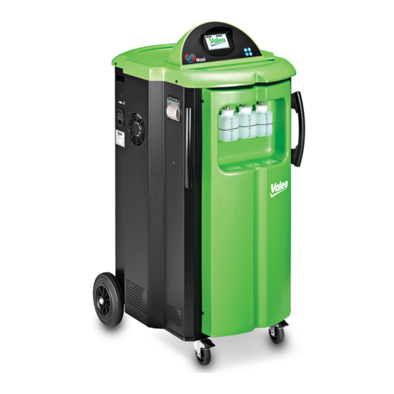
Page 16: Front View (Exterior)
ClimFill Maxi FRONT VIEW (EXTERIOR) 1. New PAG oil container 250 cc 2. Exhausted oil container 250 cc 3. UV contrast fluid container 250 cc 4. Handles ONLY MAINTENANCE TECHNICIANS MAY REMOVE THE FRONT AND REAR DOORS OR THE TOP COVER CAP. -
Page 17: Front View (Interior)
ClimFill Maxi FRONT VIEW (INTERIOR) 5. Vacuum pump 6. Refrigerant tank 40 L 7. Load cell 8. Non-condensable gas vent valve (automatic) ONLY MAINTENANCE TECHNICIANS MAY REMOVE THE FRONT AND REAR DOORS OR THE TOP COVER ENGLISH 17 / 74... -
Page 18: Rear View (Exterior)
ClimFill Maxi REAR VIEW (EXTERIOR) 9. Caster wheels, with brakes 10. Handling wheels 11. Rear door ONLY MAINTENANCE TECHNICIANS MAY REMOVE THE FRONT AND REAR DOORS OR THE TOP COVER CAP. 5 - GENERAL DESCRIPTION 18 / 74 ENGLISH... -
Page 19: Rear View (Interior)
ClimFill Maxi REAR VIEW (INTERIOR) 12. Manifold 13. Distiller 14. Dryer filter 15. Safety pressure switch 16. Oil separator 17. Vented condenser 18. Compressor ONLY MAINTENANCE TECHNICIANS MAY REMOVE THE FRONT AND REAR DOORS OR THE TOP COVER ENGLISH 19 / 74... -
Page 20: Right Side View
ClimFill Maxi RIGHT SIDE VIEW 19. HP hose and quick coupling 20. LP hose and quick coupling DO NOT USE THE UNIT UNLESS THE CHARGING HOSES (HP – LP) ARE CORRECTLY CONNECTED CAP. 5 - GENERAL DESCRIPTION 20 / 74... -
Page 21: Left Side View
ClimFill Maxi LEFT SIDE VIEW 21. RS232 serial port (updating software installation interface) 22. Main switch 23. 230 VAC MAINS SUPPLY FUSES (5x20 T 10A 250V) ENGLISH 21 / 74 CAP. 5 - GENERAL DESCRIPTION... -
Page 22: Front Side View
ClimFill Maxi FRONT SIDE VIEW 24. Touch Screen graphic display CAP. 5 - GENERAL DESCRIPTION 22 / 74 ENGLISH... -
Page 23: Touchscreen
ClimFill Maxi TOUCHSCREEN All settings, controls and service functions are available on the touchscreen display. It also displays the service equipment’s status, the progress of A/C system service and any alarms and error messages. The touchscreen is the basic operator interface and can be operated with the fingers or some other object, such as a pen. -
Page 24: Status Bar
ClimFill Maxi If you need to enter free text or identify a set of data, a keypad automatically appears (for example, for entering workshop data or at the end of the service cycle). Press for symbols STATUS BAR The status bars belong to two groups: the first two are in the upper part of the screen. - Page 25 ClimFill Maxi These indicators are always available on all the screen pages. The following status bars are available. BLUE status bar • indicates the pressure level inside the LP side (value expressed in Bar). RED status bar • indicates the pressure level inside the HP side (value expressed in Bar).
-
Page 26: Function Keys
ClimFill Maxi 5.10 FUNCTION KEYS ClimFill ® Maxi function keys are listed below: By pressing this key for at least 2 seconds, the refrigerant amount to be charged inside the vehicle A/C system may be modified. Once the value has been changed, press the icon again to quit. - Page 27 ClimFill Maxi performed through the ELECTRIC COMPRESSOR function (STANDARD type with cleaning of only internal hoses or, if the function EXTERNAL ELECTRIC COMPRESSOR FUNCTION KIT is enabled in the settings menu and the specific kit is available, the EXTERNAL ELECTRIC COMPRESSOR...
-
Page 28: Climfill ® -Lock Patented Technology Quick Couplers
ClimFill Maxi 5.11 CLIMFILL -LOCK PATENTED TECHNOLOGY QUICK ® COUPLERS ClimFill ® -Lock patented technology is the INTELLIGENT COUPLER, that with the suitable automated procedure in the software enables to: 1. reduce the non condensable gas formation inside the vessel ;... -
Page 29: Optional Accessories
ClimFill Maxi 5.13 OPTIONAL ACCESSORIES The following optional accessories are available from your reseller or commercial partner: • NITROGEN LEAK TEST KIT - Kit for leak test (under pressure conditions) with nitrogen (pressure reducer and cylinder not supplied) • EXTERNAL ELECTRIC COMPRESSOR FUNCTION KIT - Kit for cleaning of station pneumatic circuit in case POE oil for hybrid vehicles is used •... -
Page 30: Cap. 6 - Technical Features
ClimFill Maxi CAP. 6 - TECHNICAL FEATURES Vessels for R134a fluids Capacity 40 l Maximum operating pressure (PS) 20 bar PED category (Dir.97/23/EC) Weight of gas content Scale Safety valve Type Nuova General Instruments D7/S Calibration pressure 20 bar PED category (Dir.97/23/EC) - Page 31 ClimFill Maxi High intensity flushing available with external accessory (option) Database Electronic System pressure diagnostics Automatic or manual (cars only) Overall dimensions WxDxH 652x728x1198 mm Loadless weight 135 kg Power supply Frequency 50 Hz Voltage 230 V ~ Power 1000 W...
-
Page 32: Cap. 7 - Installation
ClimFill Maxi CAP. 7 - INSTALLATION EQUIPMENT INSTALLATION 7.1.1 Unpacking ClimFill ® Maxi RISK OF OVERTURNING The manufacturer disclaims all responsibility for damage to objects and/or persons resulting from the equipment being wrongly removed from the pallet, or from the... - Page 33 ClimFill Maxi ClimFill ® Maxi is supplied with the accumulation tank empty. This prevents problems in shipping the unit. GAS SCALE SCREW RELEASE The equipment is transported, with the scale blocked by a locking screw to avoid load cell damage. The scale locking screw is placed on the equipment bottom (see the box shown above) and is made up of a bolt with wing-nut.
-
Page 34: Cap. 8 - Commissioning
ClimFill Maxi CAP. 8 - COMMISSIONING CONNECTIONS The product has to be positioned on a horizontal surface to ensure the correct operation. The unit has to be connected to the electric mains following instructions on the identification plate of the product applied next to the main switch, mainly as to applicable voltage and power. - Page 35 ClimFill Maxi Connections to the A/C Power mains system connection ATTENTION: Leave the quick coupling taps closed when the unit is not in use and at the end of vehicle service operations. ENGLISH 35 / 74 CAP. 8 - COMMISSIONING...
-
Page 36: First Tank Filling
ClimFill Maxi FIRST TANK FILLING Execute the following actions in sequence by following the display guided procedure and the illustrations on the summary sheet provided with the equipment: • Gas weight check • Oil weight check • Pressure check •... -
Page 37: New Oil Bottle Filling
ClimFill Maxi The LP gauge indicates the pressure inside the external tank. After some minutes the product will automatically end the function. At the end, the weight of the charged refrigerant will be displayed. NEW OIL BOTTLE FILLING The new oil container is on the left, looking at the product from the front. -
Page 38: Detection Dye Bottle Filling
ClimFill Maxi DETECTION DYE BOTTLE FILLING The detection dye is a substance made up of a yellow-green coloured fluorescent pigment, which means that, when lit by an ultraviolet lamp, it becomes fluorescent and thus visible. The detection dye can therefore be used to detect leaks of a small entity inside the vehicle A/C system. -
Page 39: Cap. 9 - Setup
ClimFill Maxi CAP. 9 - SETUP From the SETUP menu it is possible to select parameters and activations : ELECTRIC COMPRESSOR FUNCTION • by selecting this entry, one may change the type of Oil to inject into the A/C system. Attention: the EXTERNAL ELECTRIC COMPRESSOR FUNCTION KIT (optional... - Page 40 ClimFill Maxi CLOCK ADJUSTMENT • by selecting this entry, date and time may be changed. GARAGE DATA • The type of data shown in the print-out are the following Row 1: Company name Row 2: Address Row 3: Postcode and city...
- Page 41 “database activation code”. VALEO SERVICE reserves the right to add new parameters to make the equipment increasingly versatile and adaptable to market’s needs.
-
Page 42: Cap. 10 - A/C System Recharge
ClimFill Maxi CAP. 10 - A/C SYSTEM RECHARGE 10.1 REMARKS The refrigerant recovery and the new recharge of a car A/C system work better if the car engine is hot. The service station has to be recently switched on in order to enable the possible vent of non condensable gases and complete the initial ventilation phase. -
Page 43: Non-Condensable Gas Discharge Valve
ClimFill Maxi 10.2 NON-CONDENSABLE GAS DISCHARGE VALVE The non condensable gases discharge valve has been installed in order to allow the non condensable gases and air automatic evacuation from the equipment internal tank. NON-CONDENSABLE GAS DISCHARGE VALVE WITH OUTLET EXTERNAL TO... -
Page 44: Recharge Q-Mode And S-Mode
ClimFill Maxi 10.3 RECHARGE Q-MODE AND S-MODE ClimFill ® Pro can apply two different refrigerant recharge modes; the first one is called Q-Mode (Quick mode) and features the opening of the recharge valve by injecting gas through the HP port. -
Page 45: Cap. 11 - Automatic Cycles
A/C system, is displayed (For the touchscreen use, see chap. 5.13). 5,13). 11.3.1 Vehicle selection from database VALEO SERVICE offers customers purchasing ClimFill ® Maxi the possibility of enhancing potentials of the product through the database. -
Page 46: User-Defined Cycles
ClimFill Maxi 11.3.3 User-defined cycles It allows loading the parameters of the automatic cycle previously saved by the user. 11.3.4 Search parameters by vehicle registration plate number It allows loading the parameters of the automatic cycle previously saved for a specific vehicle identified by its registration plate number. -
Page 47: Oil Type Replacement
ClimFill Maxi Besides storing the printout report data in the internal memory, the software automatically saves the cycle settings and associates them to the vehicle registration plate number, so that these settings can be reused for the same customer vehicle. -
Page 48: Cap. 12 - Manual Cycles
ClimFill Maxi CAP. 12 - MANUAL CYCLES 12.1 PRELIMINARY OPERATIONS It is necessary to connect both the LP (low pressure) – and HP (high pressure) couplers to the vehicle A/C system (Screw the valves only when required by the A/C station). -
Page 49: Injection
ClimFill Maxi 12.4 INJECTION In the main menu, select MANUAL CYCLES and then INJECTION. You can then set the injection values either from • the electronic database (excluding BUSES) or • from the last cycle, or • from the database saved by the user, or •... -
Page 50: Operation Control (Excluding Buses)
ClimFill Maxi POSSIBLE ERROR INDICATION: The amount of refrigerant in the A/C service units tank is less than that required. Closed hoses, injection impossible. 12.5 OPERATION CONTROL (EXCLUDING BUSES) The pressure check requires the engine to be started once the service equipment has been connected to the vehicle. -
Page 51: Nitrogen Test
ClimFill Maxi • “Standard” – for which you need to buy the optional kit for the connection of the station hoses to the components to be flushed, • “High flushing mode” or high intensity flushing, for which you need to buy the previous kit as well as an external optional accessory. -
Page 52: Cap. 13 - Maintenance
ClimFill Maxi CAP. 13 - MAINTENANCE ClimFill ® Maxi is a highly reliable A/C service station with excellent quality parts, manufactured with the most advanced available production techniques. The equipment contains pressurised parts with safety equipment to eliminate associated risks. -
Page 53: Self Leak Test
ClimFill Maxi • trained in maintenance in line with the instructions given in the use and maintenance manual. INTERVENTIONS ON SERVICE STATION COMPONENTS WHICH ARE NOT MENTIONED IN THE FOLLOWING PARAGRAPHS ARE PROHIBITED. MAKE SURE THE EQUIPMENT IS UNPLUGGED FROM THE POWER MAINS BEFORE OPENING. - Page 54 ClimFill Maxi After 1000 hours of vacuum pump operation since the last oil change, the PUMP MONITORING SYSTEM procedure cannot be activated anymore and you have to replace the oil according to the following instructions. Required equipment: Medium crosshead screwdriver...
-
Page 55: Dryer Filter Change
ClimFill Maxi 13.3 DRYER FILTER CHANGE The software will notify when the dryer filer of ClimFill ® Maxi must be replaced (see Chap. 13.3.2). To replace the filters, select FILTERS REPLACEMENT from the MAINTENANCE Menu and press on the display. (For the touchscreen use, see chap. 5.8) Equipment: •... - Page 56 ClimFill Maxi 5. Unscrew the bolts securing the rear door. Position of the rear door. Position of the fixing screws to be unscrewed using a cross-tip screwdriver. 6. Remove the strap that winds up the filter 7. Unscrew the 2 connection nuts of the filter by means of the hex keys.
- Page 57 ClimFill Maxi Unscrew the lower nut of the filter using a 24-mm and 17-mm hex key in order to block the filter and lever with it as shown in the next photo. 8. Set the new filter in the position shown by the arrow in the next photo; pay attention to the position of the gaskets and to the direction of the arrow on the filter label showing the liquid flow.
-
Page 58: Message For Filter Almost Exhausted
ClimFill Maxi Position of the fixing screws to be screwed using a cross-tip screwdriver. 11. Reconnect the electric cable to the mains and switch the device on using the circuit breaker. 12. Carry out the automatic leak test requested by the software when switched on again after the filter replacement. -
Page 59: Non-Condensable Gas Discharge
ClimFill Maxi Check that the equipment hoses are not connected and positioned in the hose winder. Start the procedure that initially implies the creation of vacuum in the internal tank. This phase will take 15 minutes and will act on the whole equipment. -
Page 60: System Information
ClimFill Maxi 13.8 SYSTEM INFORMATION By selecting this function, you can display the identifying codes and the electronic boards software version of the ClimFill ® Maxi station. 13.9 MAINTENANCE OF PRINTER To change the roll of paper follow instructions below: Open the lid of the printer as shown. - Page 61 ClimFill Maxi • the bodies in charge, after the results of the previous checks performed (of commissioning or period requalification) do not establish different frequencies. The checks must be performed by the bodies in charge in the country where ClimFill ®...
- Page 62 ClimFill Maxi SUCTION UNIT ClimFill ® Maxi Art. 3.3 (Dir. 97/23/EC) • Make sure no corrosion and leakages are present. PRESSURE SWITCH 13/18bar 1/4SAE Category IV (Dir. 97/23/EC) • Check presence of the device with references indicated above, wholeness of connection cables and connector, and the correct connection to the equipment printed circuit board.
-
Page 63: Cap. 14 - Disposal
ClimFill Maxi CAP. 14 - DISPOSAL 14.1 A/C SERVICE UNIT DISPOSAL At the end of its service life, the unit must be disposed of as follows: • Contact the service centre to have the refrigerant in the unit recovered and recycled. -
Page 64: Cap. 15 - Spare Parts
VALEO SERVICE. WARNING Using non-original / unapproved spare parts or accessories can compromise the safety of ClimFill Maxi. ® VALEO SERVICE recommends using original VALEO SERVICE parts or parts of equivalent quality. CAP. 15 - SPARE PARTS 64 / 74 ENGLISH... -
Page 65: Cap. 16 - Message And Alarm Codes
CLIMFILL MAXI CAP. 16 - MESSAGE AND ALARM CODES Please find below the list of message and alarm codes that could be detected by the software of the ClimFill ® Maxi station. If there are alarms, it is advisable to apply to Your supplier or service Partner. - Page 66 ClimFill Maxi CODE MESSAGE When it occurs Possible Actions situations W036 FURTHER OIL During oil Insufficient Increase the vacuum INJECTION NOT injection phase vacuum level phase time, check the POSSIBLE A/C system tightness. W044 VESSEL EMPTY During flushing Gas level is...
- Page 67 ClimFill Maxi Alarm messages are coded Axxx in the window title bar. Alarms immediately terminate the procedure and prevent its resumption. CODE MESSAGE When it can Possible Actions occur causes A000 EEPROM NOT Electronics EEPROM Replace the logic fault WORKING...
- Page 68 ClimFill Maxi CODE MESSAGE When it can Possible Actions occur causes A033 CIRCUIT LEAKAGE During Leakage in the Identify the leak position vacuum, circuit or in the in the vehicle or vessel filling vehicle fittings. connected system and or leak test...
- Page 69 ClimFill Maxi CODE MESSAGE When it can Possible Actions occur causes A037 FURTHER During gas Hoses not Caution: before REFRIGERANT injection phase connected to proceeding, empty INJECTION NOT vehicle A/C out the hoses. POSSIBLE system; tap Repeat the recovery closed;...
- Page 70 ClimFill Maxi CODE MESSAGE When it can Possible Actions occur causes A047 LP LEAKAGE During the At the end of Empty the vehicle gas recovery the gas (follow the procedure and hoses injection, in guided by the emptying the ClimFill ®...
-
Page 71: Cap. 17 - Maintenance Forms
ClimFill Maxi CAP. 17 - MAINTENANCE FORMS ClimFill ® Maxi Serial Number……………………………… MAINTENANCE FORM Vacuum pump oil change Date Maintenance technician identification Maintenance technician signature and stamp ENGLISH 71 / 74 CAP. 17 - MAINTENANCE FORMS... - Page 72 ClimFill Maxi MAINTENANCE FORM Dryer filter change Date Maintenance technician identification Maintenance technician signature and stamp CAP. 17 - MAINTENANCE FORMS 72 / 74 ENGLISH...
- Page 73 ClimFill Maxi MAINTENANCE FORM Gas receiver load cell check Date Result of check Maintenance Maintenance (pass/fail) technician technician signature identification and stamp ENGLISH 73 / 74 CAP. 17 - MAINTENANCE FORMS...
- Page 74 ClimFill Maxi MAINTENANCE FORM Other checks/maintenance/repairs Date Result of Maintenanc Maintenance technician check e technician signature and stamp (pass/fail) identification CAP. 17 - MAINTENANCE FORMS 74 / 74 ENGLISH...
Need help?
Do you have a question about the ClimFill Maxi and is the answer not in the manual?
Questions and answers