Texas Instruments TRF7970A User Manual
Evaluation module
Hide thumbs
Also See for TRF7970A:
- Manual (91 pages) ,
- Instruction manual (88 pages) ,
- Getting started manual (23 pages)
Table of Contents
Advertisement
The Texas Instruments TRF7970A evaluation module (EVM) is intended to be used by to demonstrate the
capabilities of the TRF7970A and help aid in the development process by providing a working
hardware/firmware reference example for traditional HF (13.56 MHz) RFID and also NFC Forum
operations.
This manual includes a list of EVM features, a brief description of the module, EVM specifications, details
on connecting and using the EVM, and a discussion of the software interface for the EVM.
MSP430, Stellaris, Sitara are trademarks of Texas Instruments.
Cortex, ARM8, ARM9 are trademarks of ARM Corporation.
MIFARE is a trademark of NXP Semiconductors.
FeliCa is a trademark of Sony Corporation.
All other trademarks are the property of their respective owners.
SLOU321 – August 2011
Submit Documentation Feedback
TRF7970A Evaluation Module (EVM)
Copyright © 2011, Texas Instruments Incorporated
User's Guide
SLOU321 – August 2011
TRF7970A Evaluation Module (EVM)
1
Advertisement
Table of Contents

Related Manuals for Texas Instruments TRF7970A


Summary of Contents for Texas Instruments TRF7970A
- Page 1 SLOU321 – August 2011 TRF7970A Evaluation Module (EVM) The Texas Instruments TRF7970A evaluation module (EVM) is intended to be used by to demonstrate the capabilities of the TRF7970A and help aid in the development process by providing a working hardware/firmware reference example for traditional HF (13.56 MHz) RFID and also NFC Forum operations.
-
Page 2: Table Of Contents
Contents ....................TRF7970A EVM Description ................Using the TRF7970A EVM With PC GUI ....................... Abbreviations ......................... References List of Figures ....................TRF7970A EVM (Top Side) ..................TRF7970A EVM GUI Connected ..............Single Slot Inventory Command (One Tag in Field) ............ - Page 3 ISO/IEC 15693 Request Flags (b5 – b8) when Inventory Flag is set ....................ISO/IEC 15693 UID Format ................... Custom Commands Request Format ............Command Codes for GPI/O Controlled Outputs on EVM SLOU321 – August 2011 TRF7970A Evaluation Module (EVM) Submit Documentation Feedback Copyright © 2011, Texas Instruments Incorporated...
-
Page 4: Trf7970A Evm Description
As shipped, the TRF7970A EVM is fully functional as an RFID/NFC Forum reader/writer, NFC Forum Initiator or NFC Forum Target. To evaluate the TRF7970A beyond the standalone mode, which only requires that power be applied via the USB connector, the TRF7970A EVM GUI must be used. CAUTION The TRF7970A EVM contains components that can be potentially damaged by electrostatic discharge. -
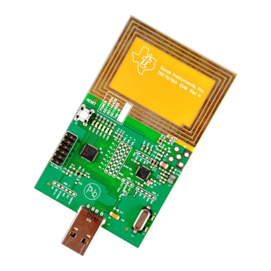
Page 5: Trf7970A Evm (Top Side)
USB Interface Figure 1. TRF7970A EVM (Top Side) If a logic analyzer is to be connected to the TRF7970A EVM, the user can install three-position 2-mm board headers at positions HDR_1 and HDR_3 for observation of DATA_CLK and IRQ signals. An 8-position 2-mm board header can be installed at position HDR_5 for observation of the parallel or SPI signals between the MSP430F2370 and the TRF7970A. - Page 6 Texas Instruments ISO15693 transponders. When the TRF7970A EVM is connected to a PC and the TRF7970A EMV GUI is started, the preloaded MSP430F2370 firmware detects this, stops the polling loop, and turns off any protocol LEDs that were illuminated to take direct host commands.
-
Page 7: Using The Trf7970A Evm With Pc Gui
TRF7970A EVM GUI Startup The TRF7970A EVM GUI has a COM port auto detect function which is limited to COM ports 1 through 12. This being the case, the user is advised that after plugging in TRF7970A EVM but before starting the... - Page 8 ISO15693 Tab By default the TRF7970A EVM GUI starts up with the ISO15693 tab selected. The user should set/select the transponder/tag request flags as appropriate for the given operation (details on this to follow for each command) and by using the Set Protocol button in the GUI first before executing any commands so that the TRF7970A register settings match what is being sent out/expected back to/from the transponder(s) in the field of the EVM antenna.
- Page 9 The ISO/IEC 15693 Inventory command is used to acquire the factory programmed and permanently locked 64 bit unique identifier(s) (UIDs) of transponders that are in within the read zone of the TRF7970A EVM antenna. They are used, as the name implies, to address each VICC uniquely and individually during the anticollision loop and for one to one exchange between a VCD and a VICC.
-
Page 10: Single Slot Inventory Command (One Tag In Field)
Using the TRF7970A EVM With PC GUI www.ti.com Figure 3. Single Slot Inventory Command (One Tag in Field) Figure 4. Single Slot Inventory Command (Two Tags in Field/Collision) SLOU321 – August 2011 TRF7970A Evaluation Module (EVM) Submit Documentation Feedback Copyright © 2011, Texas Instruments Incorporated... -
Page 11: Sixteen Slot Inventory Command (Four Tags In Field With No Collision)
2. Select the Tag Flags accordingly (see Figure 5 for one example). 3. Click Set Protocol. 4. Place tags or transponders near enough to the TRF7970A EVM antenna to be read. 5. Click Execute. Figure 5 Figure 6 for example results of multiple tags in the field without and with collisions, respectively. -
Page 12: Sixteen Slot Inventory Command (Five Tags In Field, Collision In Slot 0)
Using the TRF7970A EVM With PC GUI www.ti.com NOTE: For graphics brevity, only five tags are shown. Figure 6. Sixteen Slot Inventory Command (Five Tags in Field, Collision in Slot 0) SLOU321 – August 2011 TRF7970A Evaluation Module (EVM) Submit Documentation Feedback... -
Page 13: Read Single Block Command Example
3. Click Set Protocol. 4. Enter the Block number to be read (in hex). 5. Place tags or transponders near enough to the TRF7970A EVM antenna to be read. 6. Click Execute. Figure 7. Read Single Block Command Example SLOU321 –... -
Page 14: Write Single Block Command Example
4. Enter the Block number to be written (in hex). 5. Enter the Data to be written (in hex). 6. Place tags or transponders near enough to the TRF7970A EVM antenna to be read. 7. Click Execute. Figure 8. Write Single Block Command Example SLOU321 –... -
Page 15: Lock Block Command Example
3. Click Set Protocol. 4. Enter the Block number to be locked. 5. Place tags or transponders near enough to the TRF7970A EVM antenna to be read. 6. Click Execute. Figure 9. Lock Block Command Example SLOU321 –... -
Page 16: Read Multiple Blocks Command Example
4. Enter First Block number to be read 5. Enter number of blocks to be read (n-1) 6. Place tags or transponders near enough to the TRF7970A EVM antenna to be read. 7. Click Execute Figure 10. Read Multiple Blocks Command Example SLOU321 –... -
Page 17: Stay Quiet Command Example
Using the TRF7970A EVM With PC GUI www.ti.com 2.3.6 Write Multiple Blocks (Command Code 0x24) This optional command is not currently known to be supported by any ISO/IEC 15693 transponders available. 2.3.7 Stay Quiet (Command Code 0x02) The Stay Quiet command is a mandatory command which instructs the VICC to enter the quiet state. The command is always issued as an addressed command and of course there is no response to the Stay Quiet Command. -
Page 18: Select Command Example
Using the TRF7970A EVM With PC GUI www.ti.com 2.3.8 Select (Command Code 0x25) The Select command is an optional command that is always issued as an addressed command. If the UID sent as the address in the request matches the UID of the VICC, the VICC will enter the Selected state. -
Page 19: Reset To Ready Command Example
Using the TRF7970A EVM With PC GUI www.ti.com 2.3.9 Reset to Ready (Command Code 0x26) The Reset to Ready Command is an optional command that returns the VICC(s) in the Quiet state to the Ready state. This command can be sent as an addressed or unaddressed request and the same end result can also be achieved by turning off the activating field from the VCD or removing the VICC(s) from the activating field. -
Page 20: Write Afi Command Example
3. Click Set Protocol. 4. Enter AFI value to be written (in hex). 5. Place tags or transponders near enough to the TRF7970A EVM antenna to be read. 6. Click Execute. Figure 14. Write AFI Command Example SLOU321 –... -
Page 21: Lock Afi Command Example
Figure 15 for one example, note use of option flag). 3. Click Set Protocol. 4. Place tags or transponders near enough to the TRF7970A EVM antenna to be read. 5. Click Execute. Figure 15. Lock AFI Command Example SLOU321 – August 2011... -
Page 22: Write Dsfid Command Example
3. Click Set Protocol. 4. Enter Data to be written (in hex). 5. Place tags or transponders near enough to the TRF7970A EVM antenna to be read. 6. Click Execute. Figure 16. Write DSFID Command Example SLOU321 –... -
Page 23: Lock Dsfid Command Example
Figure 17 for one example, note use of option flag). 3. Click Set Protocol. 4. Place tags or transponders near enough to the TRF7970A EVM antenna to be read. 5. Click Execute. Figure 17. Lock DSFID Command Example SLOU321 – August 2011... -
Page 24: Get System Information Command Example
2. Select Tag Flags accordingly (see Figure 18 for one example). 3. Click Set Protocol. 4. Place tags or transponders near enough to the TRF7970A EVM antenna to be read. 5. Click Execute. Figure 18. Get System Information Command Example SLOU321 – August 2011... -
Page 25: Get Multiple Block Security Status Command Example
3. Click Set Protocol. 4. Type the first block number. 5. Type the number of blocks. 6. Place tags or transponders near enough to the TRF7970A EVM antenna to be read. 7. Click Execute. Figure 19. Get Multiple Block Security Status Command Example SLOU321 –... - Page 26 2.3.16 TI Custom Commands The TRF7970A supports the two custom commands that are outlined in the ISO/IEC 15693 standard and defined by Texas Instruments. The format outlined in the standard for custom VICC commands is shown Table 7. These commands are only supported by TI "Plus" silicon based transponders, which can be identified by part numbers containing RI-xxx-112A.
-
Page 27: Anticollision Command Example For One Type A Picc
4. Type the string E600 in String to Send window (see Figure 21). 5. Place up to two ISO/IEC14443A PICCs near enough to the TRF7970A EVM antenna to be read. 6. Click Send. SLOU321 – August 2011 TRF7970A Evaluation Module (EVM) Submit Documentation Feedback Copyright ©... -
Page 28: Anticollision Command Example For Two Type A Piccs
Using the TRF7970A EVM With PC GUI www.ti.com Figure 21. Anticollision Command Example for Two Type A PICCs SLOU321 – August 2011 TRF7970A Evaluation Module (EVM) Submit Documentation Feedback Copyright © 2011, Texas Instruments Incorporated... -
Page 29: Select Command Example
Using the TRF7970A EVM With PC GUI www.ti.com 2.4.2 Select, RATS, and PPS The Select command radio button is automatically selected after the anticollision loop is complete when using the ISO14443A tab, because this command cannot be issued to a PICC until the UID is obtained. -
Page 30: Rats Command Example
Using the TRF7970A EVM With PC GUI www.ti.com Figure 23. RATS Command Example 2.4.3 HLTA and Deselect These commands are available in the GUI as needed to demonstrate stopping a card from responding while it remains in the field (HLTA) or to reset a card back to ready state once it has been selected (Deselect). -
Page 31: Req_B Command Example
Using the TRF7970A EVM With PC GUI www.ti.com ISO14443B Tab The ISO14443B tab is used to perform Layer 3 and into Layer 4 operations on ISO14443B PICCs according to the ISO/IEC144443-4 standard. After selecting this tab, select the Set Protocol button. -
Page 32: Attrib Command Example
2.5.3 ATTRIB This command is used to select an ISO14443B PICC and bring it into Layer 4. REQ_B should be sent before this command so that the TRF7970A system has the information that is required in this command (see Figure 25). -
Page 33: Felica Polling Example
The Find Tags tab is a GUI-controlled version of the standalone mode that the reader defaults to when powered up but before the TRF7970A EVM GUI is executed. When this tab is selected, all of the supported protocols are selected to be polled for. Deselect any of the protocols that are not desired and... - Page 34 Using the TRF7970A EVM With PC GUI www.ti.com Figure 27. Find Tags Tab Example 1 Figure 28. Find Tags Tab Example 2 SLOU321 – August 2011 TRF7970A Evaluation Module (EVM) Submit Documentation Feedback Copyright © 2011, Texas Instruments Incorporated...
-
Page 35: Registers Tab
Registers Tab The Registers tab is used to retrieve the values in the TRF7970A registers and to directly change the values of those registers. Some of the register settings are coded in the TRF7970A EVM firmware for the various protocols commands;... -
Page 36: Setting Up Trf7970A Evm As Initiator
Figure 30. Setting up TRF7970A EVM as Initiator 2.9.2 Target Setup To set the second TRF7970A as a Target (Slave) (after connecting on the second PC) (see Figure 31): 1. Click the NFC-PP tab. 2. Check the Target Box in the Protocol Flags section of the GUI window. -
Page 37: Demonstration Hardware Configuration Example
Using the TRF7970A EVM With PC GUI www.ti.com After setting up the two separate TRF7970A evaluation modules, they should be arranged in a parallel orientation relative to each other for the best coupling/best performance (see Figure 32). Figure 32. Demonstration Hardware Configuration Example SLOU321 –... -
Page 38: Peer-To-Peer Connection Step
Using the TRF7970A EVM With PC GUI www.ti.com 2.9.3 Peer-to-Peer Connection Step To connect the two TRF7970A evaluation modules (see Figure 33): 1. In the GUI for the Initiator, click Connect (the button then changes to Disconnect). 2. The Initiator and Target GUI indicators turn green when connection is successful. -
Page 39: Nfc File Transfer, Select File On Initiator
Using the TRF7970A EVM With PC GUI www.ti.com 2.9.5 NFC File Transfer While still in Initiator and Target modes as described in Section 2.9.3, files can also be transferred. This is done by selecting a file to be sent from the Initiator side and also a location (a file folder or directory) to store the file on the Target. -
Page 40: Card Emulation Mode
For card emulation mode, one TRF7970A EVM should be set up as a Target (see Section 2.9.2). Another TRF7970A EVM can be used as an RFID reader (in this example, the device is set up and used as an ISO14443A reader; see Section 2.4). - Page 41 These examples are using the Send button which adds on the necessary bytes before and after data to send strings are entered. This example is setting up the TRF7970A for full power out and ISO15693 operation (see...
-
Page 42: Continuous Write To Registers 0X00 To 0X0B Example
Using the TRF7970A EVM With PC GUI www.ti.com Figure 39. Continuous Write to Registers 0x00 to 0x0B Example Figure 40. Continuous Read from Registers 0x00 to 0x0B Example SLOU321 – August 2011 TRF7970A Evaluation Module (EVM) Submit Documentation Feedback Copyright © 2011, Texas Instruments Incorporated... -
Page 43: Sending Gpio Control Command
Using the TRF7970A EVM With PC GUI www.ti.com 2. To turn on or off the MSP430F2370 GPIO-controlled LEDs on the EVM. These could also be used in the development environment for other functions such as turning on or off other peripherals, for digital control of reed relays and switches, etc. -
Page 44: Sending Single Slot Reqb
Using the TRF7970A EVM With PC GUI www.ti.com 3. To retrieve the PUPI from an ISO14443B tag on which anticollision has been disabled (this is most often the instance for ISO14443B cards that are being used for payment applications), thus requiring a single slot REQB to be sent. - Page 45 Vicinity Integrated Circuit Card References 1. TRF7970A Data Sheet (SLOS743) 2. TRF7970A Firmware Description (SLOA157) 3. TRF7970A Firmware Design Hints (SLOA159) 4. TRF7970A NFC BSL Application Note (SLOA160) 5. ISO/IEC 15693 (http://www.iso.org) 6. ISO/IEC 14443 (http://www.iso.org) 7. ISO/IEC18092 (http://www.iso.org) 8. ISO/IEC 21481 (http://www.iso.org) 9.
- Page 46 IMPORTANT NOTICE Texas Instruments Incorporated and its subsidiaries (TI) reserve the right to make corrections, modifications, enhancements, improvements, and other changes to its products and services at any time and to discontinue any product or service without notice. Customers should obtain the latest relevant information before placing orders and should verify that such information is current and complete.
- Page 47 EVALUATION BOARD/KIT/MODULE (EVM) ADDITIONAL TERMS Texas Instruments (TI) provides the enclosed Evaluation Board/Kit/Module (EVM) under the following conditions: The user assumes all responsibility and liability for proper and safe handling of the goods. Further, the user indemnifies TI from all claims arising from the handling or use of the goods.
- Page 48 For EVMs annotated as FCC – FEDERAL COMMUNICATIONS COMMISSION Part 15 Compliant Caution This device complies with part 15 of the FCC Rules. Operation is subject to the following two conditions: (1) This device may not cause harmful interference, and (2) this device must accept any interference received, including interference that may cause undesired operation.
- Page 49 For EVMs annotated as IC – INDUSTRY CANADA Compliant This Class A or B digital apparatus complies with Canadian ICES-003. Changes or modifications not expressly approved by the party responsible for compliance could void the user’s authority to operate the equipment. Concerning EVMs including radio transmitters This device complies with Industry Canada licence-exempt RSS standard(s).
- Page 50 Also, please do not transfer this product, unless you give the same notice above to the transferee. Please note that if you could not follow the instructions above, you will be subject to penalties of Radio Law of Japan. Texas Instruments Japan Limited (address) 24-1, Nishi-Shinjuku 6 chome, Shinjukku-ku, Tokyo, Japan http://www.tij.co.jp 【ご使用にあたっての注意】...
- Page 51 EVALUATION BOARD/KIT/MODULE (EVM) WARNINGS, RESTRICTIONS AND DISCLAIMERS For Feasibility Evaluation Only, in Laboratory/Development Environments. Unless otherwise indicated, this EVM is not a finished electrical equipment and not intended for consumer use. It is intended solely for use for preliminary feasibility evaluation in laboratory/development environments by technically qualified electronics experts who are familiar with the dangers and application risks associated with handling electrical mechanical components, systems and subsystems.
Need help?
Do you have a question about the TRF7970A and is the answer not in the manual?
Questions and answers