
Related Manuals for Franke FHBP 604 4I T B2 XS


Summary of Contents for Franke FHBP 604 4I T B2 XS
- Page 1 Manuale d’istruzioni Piano di cottura da incasso Operating and maintenance instruction for hobs Electric hobs FHBP 604 4I T B2 XS...
-
Page 2: Table Of Contents
Il piano cottura in vetroceramica ad incasso è destinato all’uso domestico. Per Gentile cliente l’imballaggio dei nostri prodotti usiamo materiali che rispettano l’ambiente, sono riciclabili ed idonei ad essere deposti o distrutti. Per questo motivo abbiamo segnalato adeguatamente i materiali per l’imballo. Quando l’apparecchio non sarà... -
Page 3: Avvertenze Importanti
• L’incasso e il collegamento elettrico dell’apparecchio alla rete può essere AVVERTENZE eseguito solo da personale specializzato. IMPORTANTI • Alcune parti dell’apparecchio si scaldano durante il funzionamento. Fate attenzione ai bambini, non lasciateli nelle vicinanze dell’apparecchio e avvertiteli del pericolo d’ustioni. •... - Page 4 • Nel pannello in vetroceramica sono stati inserite quattro zone cottura. Principio funzionamento La superficie è piatta, senza bordi, dove potrebbe accumularsi la sporcizia. piano cottura • Il pannello di cottura è dotato di zone cottura a induzione altamente funzionanti. Il calore si forma direttamente nel fondo della pentola, dove serve di più, senza inutili perdite attraverso la superficie in vetroceramica.
-
Page 5: Piano Cottura In Vetroceramica
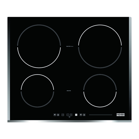
PIANO COTTURA IN VETROCERAMICA 1.Zona cottura a induzione anteriore sinistra 2.Zona cottura a induzione posteriore sinistra 3.Zona cottura a induzione posteriore destra 4.Zona cottura a induzione anteriore destra 5.Unità di comando del piano cottura Elementi di gestione piano cottura A Sensore per accensione/spegnimento piano cottura B Indicatori livello cottura o calore residuo B1 Punto decimale sull’indicatore livello cottura: - Acceso: possibile gestire zona cottura... - Page 6 La prossima impostazione deve essere eseguita in 20 secondi altrimenti il piano cottura si può spegnere di nuovo. Se avete acceso il pannello cottura con il sensore per Accensione zone cottura accensione/spegnimento (A) potete nei prossimi 20 secondi scegliere la zona cottura desiderata.
- Page 7 Accensione riscaldamento veloce, automatico • La zona cottura scelta deve essere al livello “0”. • Premendo il sensore (E) il display passa automaticamente al livello cottura 9. • Finchè il punto decimale è acceso, premete il sensore „+“ (C) della zona cottura scelta e sul display appare il simbolo „A“.
- Page 8 • Premendo il sensore»+» o »-« (G o E) impostate il tempo di cottura desiderato (da 01 a 99 minuti). L’orologio inizia a funzionare automaticamente dopo qualche secondo. La spia di controllo di zona cottura prescelta è illuminata (H1). Con l’orologio potete impostare il tempo di cottura per ogni zona cottura contemporaneamente.
-
Page 9: Procedura Di Configurazione
Quando una o più zone di cottura sono attivate, è possible interrompere il Funzione pausa processo di riscaldamento premendo il tasto pausa (F). Tutti i display di tutte le zone di cottura mostrano il simbolo di pausa “II”. Tutte le zone di cottura attive smettono di riscaldarsi. Per uscire dalla modalità... -
Page 10: Segnalazione Errori
lo rileva e viene mostrato “E4”. L’intera configurazione deve essere cancellata. ▪ In caso di una configurazione annullata non si deve effettuare nessun intervento entro i prossimi 5 secondi → gli elementi riscaldanti ad induzione dovrebbero essere ripristinati. Funzioni di sicurezza e segnalazione errori. ERRORE DESCRIZIONE ERRORE ELIMINAZIONE... -
Page 11: Pulizia E Manutenzione Piano Cottura
Difetto del sensore di temperatura di un CONTATTARE IL CENTRO DI modulo induzione ASSISTENZA TECNICA AUTORIZZATO – SPECIFICANDO IL CODICE DI ERRORE PULIZIA E MANUTENZIONE PIANO COTTURA La superficie in vetroceramica deve essere pulita dopo ogni utilizzo, poichè ogni piccola macchia che rimane si brucerà sulla superficie calda. Per la manutenzione ordinaria usate detersivi speciali che formano una specie di pellicola protettiva dallo sporco. -
Page 12: Incasso Piano Cottura
INCASSO PIANO COTTURA Avvertenze importanti • L’incasso dell’apparecchio e il collegamento alla rete elettrica può essere eseguito solamente da personale qualificato. • Il rivestimento delle pareti dell’apparecchio da incasso deve essere trattato con le colle resistenti a 100°C (se non resiste a temperature così... -
Page 13: Collegamento Alla Rete Elettrica
COLLEGAMENTO ALLA RETE ELETTRICA ▪ Il collegamento elettrico può essere eseguito solo da personale qualificato. La protezione del collegamento elettrico deve rispettare le norme in vigore. ▪ I connettori di collegamento sono a portata quando aprite il coperchio dei conduttori. ▪... -
Page 14: Caratteristiche Tecniche
CARATTERISTICHE TECNICHE Tipo FHBP 604 4I T B2 XS 580 mm Larghezza 220-240 V~ or 380-415 V 2N~, 50/60 Hz Tensione nominale Sensori elettronici Tipo interruttori Zone di cottura ( Ø, mm/W ) 160 , 1400 Davanti a sinistra 180 , 1400... - Page 15 The built-in ceramic-glass cooktop is intended for household use only. Materials Dear customer! used for packaging are nature friendly and may be recycled, deposited or destroyed without any threats to the environment. In order to recognize these features, all packing materials are marked with relevant symbols. Once your appliance has become obsolete and you do not intend to use it any longer, take adequate care not to litter the environment.
- Page 16 • The appliance may be built-in and connected to the power supply only by a IMPORTANT WARNINGS qualified technician. • Particular areas of the cooktop surface (adjacent to the hotplates) are hot during operation. Prevent the children to hang around the appliance and warn them properly against the danger of burns.
- Page 17 • Ceramic glass hob is fitted with three or four hotplates. Hob surface is Hotplate function principle completely flat and smooth, without edges to accumulate dirt. • The hob is fi tted with high power induction hotplates. Heat is generated directly at the bottom of the dish, where it is most needed, without any losses through the ceramic glass surface.
- Page 18 Power Purpose Setting Off, using remaining heat Maintaining warm food, slow simmer of smaller quantities Slow simmer (continuation of cooking after a powerful start-up) Slow cooking (continuation) of larger quantities, roasting larger chunks Roasting, browning Roasting Start of cooking, roasting Automatic initial setting •...
- Page 19 CERAMIC-GLASS COOKTOP 1.Induction hotplate front left 2.Induction hotplate rear left 3.Induction hotplate rear right 4.Induction hotplate front right 5.Hob control panel Hob control elements A ON/OFF sensor B Hotplate power or remaining heat displays B1 Decimal dot on the power displays: - On: hotplate power control is possible - Off: hotplate power control is not possible C Hotplate selection and ON/OFF sensors (+)
- Page 20 After turning the hob on using the ON/OFF sensor (A), within the next 20 Turning hotplates on seconds start one of the hotplates. • Touching the desired hotplate sensor (C), its relevant power indicator indicates »0« and decimal dot (B1) is on. •...
- Page 21 hotplate and the display indicates letter “A”. • Select desired power level. Power indicator intermittently displays the “A” symbol and the selected power setting. When the fast heating period expires, hotplate switches to the pre-selected power setting, displayed constantly on the indicator. Hint •...
- Page 22 Altering preset cooking time • You can change preset cooking time whenever you wish during the hotplate operation. • Touch the hotplate ON/OFF sensor (C) to select the desired hotplate. Decimal dot (B1) is on. • Touch the timer ON/OFF sensor (G) to activate the timer. Display (H1) of the selected hotplate is fl ashing.
- Page 23 Entering the Sercice Menu: ▪ Press together “KeyLock” and “Minus” -> keep it pressed for 5 seconds. ▪ [C] and [1] are displayed in turns on Display “back left”. [1] is displayed on Display “front left”. Entering Service Menu Point for Configuration: ▪...
- Page 24 Safety functions and error display. ERROR CODE ERROR DESCRIPTION INSTRUCTION MANUAL ER03 & Permanent use of keys; Control unit cuts off after If the problem persists, CONTACT permanent 10 sec. Water or cooking utensils on the glass AUTHORIZED CENTER FOR tone above the control unit TECHNICAL ASSISTANCE -...
- Page 25 CLEANING AND MAINTENANCE OF CERAMIC-GLASS HOB Ceramic glass hob should be cleaned only when completely cooled down, preferably after each use, otherwise even the slightest stains remaining after cooking may burn into the hob surface with each following use. For regular maintenance of ceramic-glass hob use special cleansing agents, produced in such way to create protective film upon the surface.
- Page 26 MOUNTING THE BUILT-IN COOKTOP Caution ! • To avoid any possible hazard, the appliance may be installed by qualifi ed personnel only. • Panels and furniture lining of the kitchen cabinet receiving the hob must be treated with temperature resistant adhesives 100°C (otherwise they might be discoloured or deformed because of inadequate temperature resistance).
- Page 27 • Insert the hob into the cut aperture. • Press the hob firmly towards the worktop from above. CONNECTION TO THE POWER SUPPLY • Connections may be carried out by a qualifi ed technician only. The earthing protection must comply with the standing regulations. •...
- Page 28 TECNICAL INFORMATION Type FHBP 604 4I T B2 XS 580 mm Width 220-240 V~ or 380-415 V 2N~, 50/60 Hz Rating voltage Electronic sensors Type of switch Cooking zones ( Ø, mm/W ) 160 , 1400 Forward left 180 , 1400...
Need help?
Do you have a question about the FHBP 604 4I T B2 XS and is the answer not in the manual?
Questions and answers