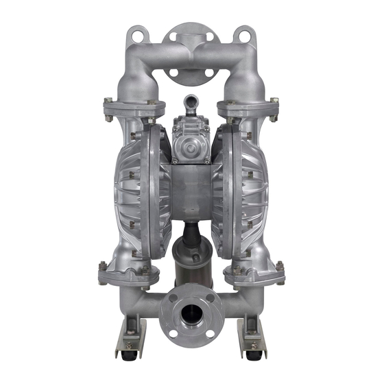
YAMADA NDP-40 Series Maintenance Manual
Air-operated double diaphragm pump
Hide thumbs
Also See for NDP-40 Series:
- Operation manual (60 pages) ,
- Operation manual (33 pages) ,
- Operation manual (24 pages)
Table of Contents
Advertisement
Quick Links
Download this manual
See also:
Operating Manual
Advertisement
Table of Contents

Related Manuals for YAMADA NDP-40 Series


Summary of Contents for YAMADA NDP-40 Series
- Page 1 Doc. No. NDP 027M-39 MAINTENANCE MANUAL YAMADA AIR-OPERATED DOUBLE DIAPHRAGM PUMP NDP-40 series NDP-50 series NDP-80 series...
-
Page 2: Warnings And Cautions
After reading this document, be sure to keep it handy for future reference. This maintenance manual covers what you should know about maintenance of the Yamada NDP-40 series, NDP-50 series and NDP-80 series Diaphragm Pumps. This edition is based on the standards for the May 2015 production run. Remember, the specifications are always subject to change;... -
Page 3: Table Of Contents
Table of Contents ·Warnings and Cautions ·Table of Contents 1. Principles of operation ·························································· 1 2. Tools, etc. 2.1 General tools ······································································· 1 2.2 Special tools ········································································ 1 2.3 Misc. ·················································································· 1 3. Ordering Replacement parts ·················································· 1 4. Balls and Valve seats 4.1 Removal ■... -
Page 4: Principles Of Operation
1. Principles of operation There are two diaphragms fixed to the center rod, one at each end. When compressed air is supplied to air chamber b (right side, see Fig.1.1), the center rod moves to the right, the material in material chamber B is pushed out, and at the same time material is sucked into material chamber A. -
Page 5: Balls And Valve Seats 4.1 Removal Ba_, Bs_, Bf_ Types
4. Balls and Valve seats 4.1 Removal ■ BA_, BS_, BF_ types ▪ Remove the 6 (8 on the NDP-80) retainer bolts “1” from the out manifold, and remove the out manifold. [Fig.4.1] ▪ Remove the ball, valve seat and O ring. [Fig.4.2] ▪... -
Page 6: Ndp-40 Bp_·Bv_ Type
■ NDP-40 BP_·BV_ type ▪ Remove the 8 retainer bolts “1” from the out manifold, and remove the out manifold. [Fig.4.4] ▪ Remove the ball, valve seat and O ring. [Fig.4.5] ▪ Remove the 8 retainer bolts “2” from the in manifold, and remove the in manifold. -
Page 7: Ndp-50 Bp_·Bv_, Ndp-80 Bp_ Types
■ NDP-50 BP_·BV_, NDP-80 BP_ types ▪ Remove the 6 (8 on the NDP-80) retainer bolts “1” from the out manifold, and remove the protector and out manifold. [Fig.4.7] ▪ Remove the ball, valve guide (only NDP-80), valve seat and O ring. -
Page 8: Inspection
4.2 Inspection ▪ Ball [Fig.4.10] Measure the outside diameter, and if it is outside the usable range, replace the ball. Usable range of ball Sø1.772 ~ Sø2.028 in NDP-40 {Sø45.0 ~ Sø51.5 mm} Sø2.232 ~ Sø2.555 in NDP-50 {Sø56.7 ~ Sø64.9 mm} Sø3.189 ~ Sø3.650 in NDP-80 {Sø81.0 ~ Sø92.7 mm}... -
Page 9: Removal ■ Ba_, Bs_, Bf_ Types
5. Diaphragm and Center rod 5.1 Removal ■ BA_, BS_, BF_ types ▪ Remove the ball and valve seat etc.(see [ 4.1 Removal BA_, BS_, BF_ types]) ▪ Remove the 16 (24 on the NDP-80) retainer bolts from the out chamber, and remove the out chamber. -
Page 10: Inspection
▪ Remove the center disk from one side using the PP wrench (special tool: Part No. 771868). [Fig.5.6] ▪ After the center disk (outside) has been removed, remove the diaphragm and the center disk (inside). Remove the center disk and center rod from the opposite side of the main body. -
Page 11: B_T Types
▪ Draw the center disk to one side (exclude B_H, B_S type cf.Fig.5.9). ▪ And install the out chamber. Tighten the bolts temporarily. ▪ Grip the inside center disk using crowbars and draw it to the opposite side, then turn the diaphragm over. (exclude B_H, B_S type) [Fig.5.10, 5.11] ▪... -
Page 12: Throat Bearing And Pilot Valve
6. Throat bearing and Pilot valve 6.1 Removal ▪ Remove the diaphragm and center rod (see [5.1 Removal]). ▪ Remove the 12 retainer bolts from the air chamber, and remove the air chamber. [Fig.6.1] ▪ Draw out the pilot valve and valve seat. [Fig.6.2] ▪... -
Page 13: C Spool Valve Assembly
7. C spool valve assembly 7.1 Removal ▪ Remove the out manifold (see [4.1 Removal]). ▪ Remove the 6 retainer bolts from the valve body, and remove the valve body. [Fig.7.1] ▪ Remove the 8 cap A and cap B retainer bolts, and remove cap A and cap B. -
Page 14: Inspection
7.2 Inspection ▪ C Spool Valve Assembly Seal ring [Fig.7.5] Measure the inside thick diameter, and if it is outside the usable range, replace the C Spool Valve Assembly. If the seal ring is worn out or cracked, replace C Spool Valve Assembly. -
Page 15: Retightening Of Tie Rods
8. Retightening of Tie rods ■ Plastic type ▪ All bolts should be retorqued: (1) Right before start up. (2) There are any leaks of material on daily inspecting a pump. Retain bolts for the Retain bolts for the out chamber manifold NDP-40.50.80 26 ft-Ibf {35 N-m}... - Page 16 YAMADA AMERICA, INC 955 E. ALGONQUIN RD., ARLINGTON HEIGHTS, IL 60005, USA PHONE: 1-847-631-9200 or 1-800-990-7867 (Toll Free) FAX : 1-847-631-9273 www.yamadapump.com Manufactured by: YAMADA CORPORATION International Department 1-1-3 CHOME, MINAMI MAGOME, OHTA-KU, TOKYO, 143-8504, JAPAN PHONE : +81-(0)3-3777-0241 FAX : +81-(0)3-3777-0584...
Need help?
Do you have a question about the NDP-40 Series and is the answer not in the manual?
Questions and answers