
Related Manuals for YAMADA NDP-P50


Summary of Contents for YAMADA NDP-P50
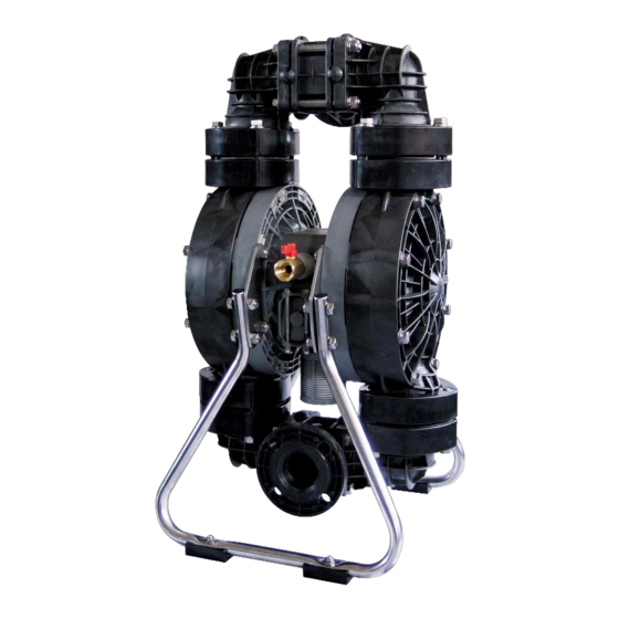
- Page 1 Doc. No. NDP 476M-03 MAINTENANCE MANUAL YAMADA AIR-OPERATED DOUBLE DIAPHRAGM PUMP NDP-P50...
-
Page 2: Warnings And Cautions
After reading this document, be sure to keep it handy for future reference. This maintenance manual covers what you should know about maintenance of the Yamada NDP-P50 series Diaphragm Pumps. This edition is based on the standards for the July 2020 production run. Remember, the specifications are always subject to change;... -
Page 3: Table Of Contents
Table of Contents Warnings and Cautions ∙ Table of Contents ∙ 1. Principles of operation ------------------------------------------------------------ 1 2. Maintenance and Tools 2.1 Maintenance ------------------------------------------------------------------------ 1 2.2 General tools ----------------------------------------------------------------------- 1 2.3 Special tools ------------------------------------------------------------------------ 1 2.4 Misc. ---------------------------------------------------------------------------------- 1 3. Ordering Replacement parts --------------------------------------------------- 2 4. -
Page 4: Principles Of Operation
1. Principles of operation There are two diaphragms fixed to the center rod, one at each end. When compressed air is supplied to air chamber b (right side, see Fig.1.1), the center rod moves to the right, the material in material chamber B is pushed out, and at the same time material is sucked into material chamber A. -
Page 5: Ordering Replacement Parts
3. Ordering Replacement parts For accurate and speedy shipment of parts, be sure to order the right parts for your model to distributor. Indicate the part numbers, descriptions, and quantities. 4. Balls and Valve seats 4.1 Removal ▪ Remove the 6 retainer bolts “1” from the out manifold, and remove the protector and out manifold. -
Page 6: Inspection
4.2 Inspection ▪ Ball [Fig.4.4] Measure the outside diameter, and if it is outside the usable range, replace the ball. Usable range of ball 56.7 - Sø64.9 mm Ø Fig.4.4 ▪ Valve seat [Fig.4.5] Measure the dimension shown at left, and if it is outside the usable range, replace the seat. -
Page 7: Diaphragm And Center Rod
5. Diaphragm and Center rod 5.1 Removal ▪ Remove the ball etc. (see “4.1 Removal”). ▪ Remove the 8 retainer bolts from the stand body, and remove the stand body. [Fig.5.1] Fig.5.1 ・Unscrew 16 bolts (include 8 bolts mentioned above) from the out chamber and remove the out chamber.[Fig.5.2] Fig.5.2 ▪... -
Page 8: Inspection
5.2 Inspection ▪ Diaphragm If the diaphragm is worn out or damaged, replace it. Never replace just one diaphragm. ▪ Center rod [Fig.5.5] Measure the diameter, and if it is outside the usable range, replace the rod. Usable range of center rod 24.93 - 25.00 mm Ø... - Page 9 ▪ Draw the center disk to one side (exclude B H, B □ □ B□H/T type cf.Fig.5.6). ▪ And install the out chamber. Tighten the bolts temporarily. ▪ Grip the inside center disk using crowbars and draw it to the opposite side, then turn the diaphragm over.
-
Page 10: Throat Bearing And Pilot Valve Assembly
6. Throat bearing and Pilot valve assembly 6.1 Removal ▪ Remove the diaphragm and center rod (see “5.1 Removal”). ① ▪ Unscrew 12 bolts (①) and 8 tapping screws (②), and remove the air chamber. [Fig.6.1] ② Fig.6.1 ▪ Pull the pilot valve and valve seat out. [Fig.6.2] ▪... -
Page 11: C Spool Valve Assembly
7. C spool valve assembly 7.1 Removal ▪ Remove the 4 cap A and cap B retainer bolts, and remove cap A and cap B. [Fig.7.1] Fig.7.1 ▪ Draw out the C spool valve assembly, and remove the seal ring from the C spool valve assembly. ▪... -
Page 12: Inspection
7.2 Inspection ▪ C Spool Valve Assembly Seal ring [Fig.7.4] Measure the inside thick diameter, and if it is outside the usable range, replace the C Spool Valve Assembly. If the seal ring is worn out or cracked, replace C Spool Valve Assembly. -
Page 13: Retightening Of Tie Rods
8. Retightening of Tie rods ▪ All bolts should be retorqued: (1) Right before start up. (2) There are any leaks of material on daily inspecting a pump. Retain bolts for the Retain bolts for out chamber the manifold 35 N・m 20 N・m <NOTE>... - Page 14 YAMADA EUROPE B.V . Aquamarijnstraat 50,7554 NS Hengelo (O),The Netherlands PHONE : +31-(0)74-242-2032 : +31-(0)74-242-1055 E-mail : sales@yamada.nl : www.yamada-europe.com Manufactured by YAMADA CORPORATION INTERNATIONAL DEPARTMENT 1-1-3, Minami-Magome,Ota ku, Tokyo, 143-8504, Japan PHONE : +81-(0)3-3777-0241 : +81-(0)3-3777-0584 E-mail : intl@yamadacorp.co.jp : www.yamadacorp.co.jp...
Need help?
Do you have a question about the NDP-P50 and is the answer not in the manual?
Questions and answers