
Related Manuals for YAMADA NDP-H50


Summary of Contents for YAMADA NDP-H50
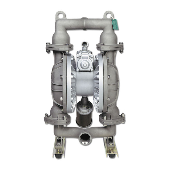
- Page 1 Doc. No. NDP 306M-06 MAINTENANCE MANUAL YAMADA AIR-OPERATED DOUBLE DIAPHRAGM PUMP NDP-H40 NDP-H50 NDP-H80...
-
Page 2: Warnings And Cautions
After reading this document, be sure to keep it handy for future reference. This maintenance manual covers what you should know about maintenance of the Yamada NDP-H40 series, NDP-H50 series and NDP-H80 series Diaphragm Pumps. This edition is based on the standards for the March 2018 production run. Remember, the specifications are always subject to change;... -
Page 3: Table Of Contents
, BS , BF types ---------------------------------------------------------- 2 ■ □ NDP-H40 BP types ------------------------------------------------------------ 3 ■ □ NDP-H50•H80 BP types ----------------------------------------------------- 4 4.2 Inspection ------------------------------------------------------------------------------ 5 4.3 Installation ---------------------------------------------------------------------------- 5 5.Diaphragm, Center rod and Center bushing 5.1 Removal ■ □ □... -
Page 4: Principles Of Operation
1.Principles of operation There are two diaphragms fixed to the center rod, one at each end. When compressed air is supplied to air chamber b (right side, see Fig.1.1), the center rod moves to the right, the material in material chamber B is pushed out, and at the same time material is sucked into material chamber A. -
Page 5: Balls And Valve Seats 4.1 Removal Ba , Bs , Bf Types
4.Balls and Valve seats 4.1 Removal ■ □ □ □ , BS , BF types ▪ Remove the 6 (8 on the NDP-H80) retainer bolts 1 from the out manifold, and remove the out manifold. [Fig.4.1] ▪ Remove the ball, valve seat and O ring. [Fig.4.2] ▪... -
Page 6: Ndp-H40 Bp □ Types
■ □ NDP-H40 BP type ▪ Remove the 8 retainer bolts 1 from the out manifold, and remove the out manifold. [Fig.4.4] ▪ Remove the ball, valve seat and O ring. [Fig.4.5] ▪ Remove the 8 retainer bolts 2 from the in manifold, and remove the in manifold. -
Page 7: Ndp-H50•H80 Bp Types
■ □ NDP-H50 H80 BP types • ▪ Remove the 6 (8 on the NDP-H80) retainer bolts 1 from the out manifold, and remove the protector and out manifold. [Fig.4.7] ▪ Remove the ball, valve guide (only NDP-H80), valve seat and O ring. -
Page 8: Inspection
NDP-50 25 N•m NDP-80 <NOTE> ▪ Make sure there is no dust on the seal surface and the seal is not damaged. ▪ Match the convex and concave parts of the protector. □ □ [Fig.4.12] ( NDP-H50 BP •H80 BP... -
Page 9: Diaphragm, Center Rod And Center Bushing
5. Diaphragm, Center rod and Center bushing 5.1 Removal ■ □ □ □ , BS , BF types □ ▪ Remove the ball and valve seat etc.(see [4.1 Removal BA □ □ , BF types] on P.2) ▪ Remove the 16 (24 on the NDP-H80) retainer bolts from the out chamber, and remove the out chamber. -
Page 10: Installation ■ B □ C, B □ N, B □ E, B □ V, B □ H, B □ S, B □ H/T Types
▪ Remove the center disk from one side using the PP wrench (special tool: Part No. 771868). [Fig.5.6] ▪ Then, remove the diaphragm, center disk inside and center bushing on the same side. Pull out the other diaphragm, center disk inside and center bushing together with the center rod from the main body. -
Page 11: B T Type
□ □ ▪ Draw the center disk to one side (exclude B H, B □ H/T types cf. Fig.5.10).and install the out chamber. tighten the bolts temporarily. ▪ Grip the inside center disk using crowbars and draw it to the opposite side, then turn the diaphragm over. □... -
Page 12: Throat Bearing And Pilot Valve Assembly
6.Throat bearing and Pilot valve assembly 6.1 Removal ▪ Remove the diaphragm and center rod (see [5.1 Removal] on P.6-7). ▪ Unscrew the tapping screws with a Phillips-head screw driver. [Fig.6.1] ▪ Remove the throat bearing using a special tool (804129). [Fig.6.1] ▪... -
Page 13: Valve Body Assembly
7.Valve Body Assembly 7.1 Removal ▪ Remove the silencer. ▪ Remove the 2 retainer bolts from the valve body, and remove the valve body. [Fig.7.1] ▪ Disconnect in the same way both up and down. ▪ Unscrew all four screws securing the guide plate and remove the block, spring and ball. -
Page 14: Inspection
7.2 Inspection ▪ Block [Fig.7.4] Measure the thickness and if it is not within the permissible range, replace with a new one. Also, replace the block if its sliding surface is worn out. Usable range of seal ring 11.4 mm~11.55 mm ▪... -
Page 15: Valve Switcher
8. Valve switcher 8.1 Removal ▪ Remove the diaphragm and center rod. (see [5.1 Removal] on P.6-7) ▪ Remove the 12 retainer bolts from the air chamber, and remove the air chamber. ▪ Remove the valve body assembly. (see [7.1 Removal] on P.10) ▪... -
Page 16: Retightening Of Tie Rods
Retain bolts for the out chamber. the manifold. NDP-H40 BP□ 35 N・m 20 N・m NDP-H50 NDP-H80 < > NOTE ▪ Retighten the Out chamber and then the manifold in this order. [Fig.9.1] ▪ Tighten the bolts in the order shown. - Page 18 Manufactured by YAMADA CORPORATION INTERNATIONAL DEPARTMENT No.1-3, 1-Chome, Minami- Magome, Ohta-Ku, Tokyo, 143-8504, Japan PHONE : +81-(0)3-3777-0241 : +81-(0)3-3777-0584 201804 NDP306M...
Need help?
Do you have a question about the NDP-H50 and is the answer not in the manual?
Questions and answers