Advertisement
Quick Links
INSTALLATION INFORMATION
EMG MODEL:B157 EMG PICKUP BUSS FOR 2 PICKUPS
USING A SELECTION SWITCH
(ACTIVE OR PASSIVE EMG PICKUPS)
General INFORMATION:
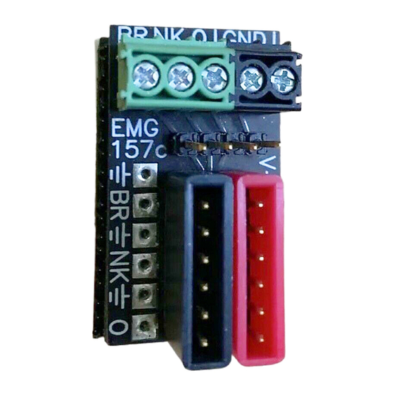
The B157 EMG Pickup Buss provides a convenient way to install EMG Pickups without soldering. The buss includes an input/output section for
the pickup signals. A V+ Supply buss for supplying the pickups and accessories with battery power. A two section terminal block and additional
header for connecting the selection switch and any ground wires. In addition, solder pads are provided for both the Input/Output section and the
V+ Supply buss so older EMG Pickups without connectors can be easily soldered to both busses.
The Pickup Buss can also be used for passive EMG-HZ Pickups.
The EMG Pickup Buss has 4 main sections.
All 4 sections are typically used, so read the
instructions and use the diagrams for assistance.
Section 1) Pickup Input/Output Buss:
This is the 6 pin header with the BLACK shroud.
Diagram #1 (Master Volume / Master Tone Controls)
This diagram shows the pickups plugged directly into the Input/Output
buss (Positions 1 and 2). Use diagram #1 if your guitar has only a
Master Volume, or only a Master Volume and Master Tone.
The output of the buss (Position 3) will go to the Master Volume Control,
then to the tone control, and finally to the output jack.
Diagram #2 (Separate Volumes for each Pickup)
This diagram shows the pickups plugged into the volume controls, then
into the Input/Output buss (Positions 1 and 2). Use diagram #2 If your
guitar has a separate Volume control for each pickup. The output of the
buss (Position 3) can go directly to the output jack as shown in diagram #2,
or it might go to a Master Tone Control, then to the output jack.
Soldering to the Input/Output Buss
If you have an older EMG Pickup without connectors, you can connect the
to the Input/Output buss by soldering to the pads provided.
Diagram #3
(INPUT BRIDGE PICKUP)
(INPUT NECK PICKUP)
© 2009 Copyright EMG INC. All Rights Reserved.
4) Ground Block (BLACK)
2a) Switch Header (Alternate switch send and return)
2) Switch Block
Pickup send and return from the selection switch (GREEN)
V+
- Ground
B - Bridge P/U
N - Neck P/U
O - Output
B
N
O
(OUTPUT)
(SHIELD=GROUND)
(WHITE WIRE=SIGNAL)
3) V+ Supply Buss
1) Pickup Input/Output Buss
Diagram #1
BRIDGE PICKUP
NECK PICKUP
Diagram #2
BRIDGE PICKUP IN AFTER VOLUME
NECK PICKUP IN AFTER VOLUME
FROM NECK PICKUP
FROM BRIDGE PICKUP
V+
.750
B
N
O
1.325
.725
BRIDGE PICKUP INPUT (POSITION 1)
NECK PICKUP INPUT (POSITION 2)
OUTPUT (POSITION 3)
OUTPUT CABLE TO
MASTER VOLUME
OUTPUT
OUTPUT CABLE TO JACK
NK VOLUME
BR VOLUME
Advertisement

Related Manuals for EMG B157 Pickup Buss


Summary of Contents for EMG B157 Pickup Buss
- Page 1 General INFORMATION: The B157 EMG Pickup Buss provides a convenient way to install EMG Pickups without soldering. The buss includes an input/output section for the pickup signals. A V+ Supply buss for supplying the pickups and accessories with battery power. A two section terminal block and additional header for connecting the selection switch and any ground wires.
- Page 2 Diagram #7 as shown. Tighten the screws with a small screwdriver. The V+ Supply buss distributes 9V+ to the pickups and any EMG Two styles of switch are shown, toggle (diagram #4) and lever (diagram #5) Accessory circuits such as the SPC, EXG, RPC, or BT.
Need help?
Do you have a question about the B157 Pickup Buss and is the answer not in the manual?
Questions and answers