Advertisement
Quick Links
Operating instructions
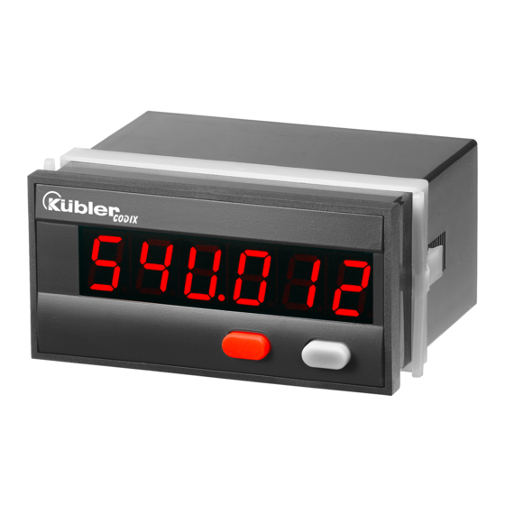
Electronic display counter
C C O O D D I I X X 5 5 4 4 U U
1.1 Safety instructions and warnings
Only use this display
– in a way according to its intended
!
purpose
– if its technical condition is perfect
– adhering to the operating
instructions and the general
safety instructions.
1.2 General safety instructions
1. Before carrying out any installation or maintenance
work, make sure that the power supply of the digital
display is switched off.
2. Only use this digital display in a way according to its
intended purpose:
f its technical condition is perfect.
Adhering to the operating instructions and the gen-
eral safety instructions.
3. Adhere to country or user specific regulations.
4. The digital display is not intended for use in areas
with risks of explosion and in the branches exclud-
ed by the standard EN 61010 Part 1.
5. The digital display shall only operated if it has been
correctly mounted in a panel, in accordance with
the chapter "Main technical features".
1.3 Use according to the intended
purpose
The digital display may be used only as a panel-
mounted device. Applications of this product may
be found in industrial processes and controls, in
manufacturing lines for the metal, wood, plastics,
paper, glass, textile and other processing indus-
tries.
Over-voltages at the terminals of the digital dis-
play must be kept within the limits in Category II
If the digital display is used to monitor machines
or processes in which, in case of a failure of the
device or an error made by the operator, there
might be risks of damaging the machine or caus-
ing accidents to the operators, it is your responsi-
bility to take appropriate safety measures.
1.4 Description
CODIX 54U is a multipurpose device. Depending
on the programmed basic function, the device
operates like
• an electronic totaliser and frequency meter
(see page 2)
• an electronic display counter with
2 totalising ranges (see page 4)
• an electronic totaliser and time meter
(see page 6)
• an electronic time meter with 2 time ranges
(see page 9)
2. Setting of the operating parameters
a. Press both front side keys keys and switch on
the supply voltage or, if the supply voltage is
already on, press both keys simultaneously
during 5 s.
b. The display shows
c. After releasing the keys, the display shows
c1.Hold the left key pressed and press the right
key to leave the programming operation.
c2. Press the right key to switch to
.
d. Hold the left key pressed and press the right
key to switch to the first parameter.
13
Advertisement

Related Manuals for Kübler CODIX 54U


Summary of Contents for Kübler CODIX 54U
- Page 1 C C O O D D I I X X 5 5 4 4 U U 1.1 Safety instructions and warnings 1.4 Description Only use this display CODIX 54U is a multipurpose device. Depending – in a way according to its intended on the programmed basic function, the device purpose operates like –...
- Page 2 Electronic totaliser and frequency e. After releasing the keys, the display alter- meter nates between the menu title and the current menu item setting. After pressing any key, C C o o d d i i x x 5 5 4 4 U U : basic operating mode only the menu item setting is displayed.
- Page 3 4.1 Polarity of the inputs 4.6 RESET-Mode (totaliser) manual reset via the red npn: switching for 0 V RESET key and electrical reset via the RESET input pnp: switching for +U B no reset (red RESET key and RESET input locked) 4.2 Switching on the 30 Hz filter (INP A) only electrical reset via the RESET input...
- Page 4 4.10 Display mode (frequency meter) Electronic display counter with 2 totalising ranges C C o o d d i i x x 5 5 4 4 U U : basic operating mode Value conversion and display in 1/s Value conversion and display in 1/min 1.
- Page 5 4.1 Polarity of the inputs 4.6 RESET mode (totaliser 1) manual reset via the red npn: switching for 0 V RESET key and electrical reset via the RESET input pnp: switching for +U B no reset (red RESET key and RESET input locked) 4.2 Switching on the 30 Hz filter (INP A) only electrical reset via the 30 Hz filter off (f max )
- Page 6 4.8 End of programming Electronic totaliser and time meter C C o o d d i i x x 5 5 4 4 U U : basic operating mode The programming routine is repeated once more. The values set until now can be checked and mod- ified.
- Page 7 4.5 Decimal point (totaliser) 4. Programming routine The programmable parameters of the device are The decimal point defines described below, in the order in which they can the way of displaying the be set. The device is fully programmed after one count values.
- Page 8 4.8 Operating mode (time meter) 4.10 RESET mode (time meter) manual reset via the red Time unit: seconds (accu- RESET key and electrical racy depending on posi- reset via the RESET input tion of the decimal point*) Time unit: minutes (accu- no reset (red RESET key racy depending on posi- and RESET input locked)
-
Page 9: Time Ranges
Electronic tim meter with 2 time ranges C C o o d d i i x x 5 5 4 4 U U : basic operating mode 4. Programming routine 1. Description • 6 digit time meter with Reset function The programmable parameters of the device are •... - Page 10 4.3 Input mode (time meter) 4.5 Decimal point The decimal point defines the resolution of the pro- grammed time unit. Start/Stop via Inp B. Counting while Inp B (Gate) not active or open 1/10 (0,1) 0.00 1/100 (0,01) Start/Stop via Inp B. 0.000 1/1000 (0,001) Counting while Inp B (Gate) active (High level with...
- Page 11 4.8 End of programming DC power supply: 24 12 V DC 10 ...30 V DC Input level: Standard typ. low level: 2,5 2,0 V 1,0 V typ. ligh level: 22,0 10 V 4,0 V The programming routine Fmax: kHz kHz is repeated once more.
- Page 12 7. Delivery includes: EMC: In compliance with the EC Directive 89/36/EEC Digital display Noise emission EN 61 000-6-3/ 2 pin screw terminal RM 5.08 EN 55 011 Class B 7 pin screw terminal RM 3.81 Noise immunity EN 61 000-6-2 Panel mounting clip Seal Housing:...
Need help?
Do you have a question about the CODIX 54U and is the answer not in the manual?
Questions and answers