Advertisement
Quick Links
Rosemount
Factory assembled, leak-tested, and calibrated
Full breadth of offering including integral, in-line, and conventional
Integral design enables "flangeless" connection to instrument
Block and bleed, 2-, 3-, and 5-valve configurations
Compact, lightweight design
Easy in-process calibration
Direct-mount capability
®
Available in NACE
-compliant materials of construction
™
Manifolds
Product Data Sheet
August 2016
00813-0100-4733, Rev PE
Advertisement

Related Manuals for Emerson Rosemount 304

Summary of Contents for Emerson Rosemount 304
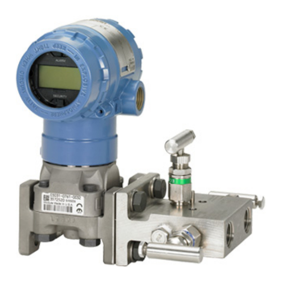
- Page 1 Product Data Sheet August 2016 00813-0100-4733, Rev PE ™ Rosemount Manifolds Factory assembled, leak-tested, and calibrated Full breadth of offering including integral, in-line, and conventional Integral design enables “flangeless” connection to instrument Block and bleed, 2-, 3-, and 5-valve configurations ...
- Page 2 50% fewer leak points than conventional transmitter to flange to manifold interface Female NPT process connections Rosemount 304 Conventional Manifold - Traditional Style Rosemount 305 Integral Manifold - Rosemount 305 Integral Manifold - Coplanar Style Traditional Style Rosemount 306 In-line Manifold “Rosemount mounting brackets”...
-
Page 3: Valve Configuration
Process Isolate Isolate Process Two-valve Rosemount 304 (Traditional) Manifold The 2-valve configuration is available on Rosemount 305, 306, and 304 Manifolds for use with absolute and gage pressure Transmitter transmitters. An isolate valve provides instrument isolation and a drain/vent valve allows venting, draining, or calibration. -
Page 4: Ordering Information
Transmitter Rosemount 305 Integral Manifold, see page Rosemount 306 In-line Manifold, see page Vent Vent Rosemount 304 Conventional Manifold, see page Equalize Isolate Isolate Transmitter/manifold assembly Process 1. Specify a completed Rosemount transmitter model number by referencing the applicable product data sheet. - Page 5 August 2016 Rosemount Manifolds Specification and selection of product materials, options, or components must be made by the purchaser of the equipment. See page 12 for more information on material selection. Table 2. Rosemount 305 Integral Manifold Ordering Information ★ The Standard offering represents the most common options. The starred options (★) should be selected for best delivery. The Expanded offering is subject to additional delivery lead time.
- Page 6 Rosemount Manifolds August 2016 Table 2. Rosemount 305 Integral Manifold Ordering Information ★ The Standard offering represents the most common options. The starred options (★) should be selected for best delivery. The Expanded offering is subject to additional delivery lead time. Mounting brackets ★...
- Page 7 August 2016 Rosemount Manifolds Specification and selection of product materials, options, or components must be made by the purchaser of the equipment. See page 12 for more information on material selection. Table 3. Rosemount 306 Pressure Manifold Ordering Information ★ The Standard offering represents the most common options. The starred options (★) should be selected for best delivery. The Expanded offering is subject to additional delivery lead time.
- Page 8 Rosemount Manifolds August 2016 Table 3. Rosemount 306 Pressure Manifold Ordering Information ★ The Standard offering represents the most common options. The starred options (★) should be selected for best delivery. The Expanded offering is subject to additional delivery lead time. (3)(7) Material recommendations for NACE ★...
- Page 9 12 for more information on material selection. Table 4. Rosemount 304 Conventional Manifold Ordering Information ★ The Standard offering represents the most common options. The starred options (★) should be selected for best delivery. The Expanded offering is subject to additional delivery lead time.
- Page 10 Rosemount Manifolds August 2016 Table 4. Rosemount 304 Conventional Manifold Ordering Information ★ The Standard offering represents the most common options. The starred options (★) should be selected for best delivery. The Expanded offering is subject to additional delivery lead time.
- Page 11 August 2016 Rosemount Manifolds Only available with option code NG. Only available with manifold type code 6. Only allowed with both manifold style code T and process connection code F. Not allowed with Graphite-based packing code 2. Only available with manifold style code 6. Only available with option codes DV and DH.
-
Page 12: Specifications
(e.g. all chemical components, temperature, pressure, flow rate, abrasives, contaminants), when specifying product, materials, options and components for the particular application. Emerson is not in a position to evaluate or guarantee the compatibility of the process fluid or other process parameters with the product, options, configuration or materials of construction selected. - Page 13 August 2016 Rosemount Manifolds Figure 2. Rosemount 306 In-line Manifolds Table 6. Rosemount 306 In-line Manifolds Packing Seat Pressure and temperature ratings 10000 psi @ 85 °F (689 bar @ 29 °C) PTFE Integral 4000 psi @ 400 °F (276 bar @ 204 °C) 6000 psi @ 200 °F (414 bar @ 93 °C) Graphite Integral...
- Page 14 Rosemount Manifolds August 2016 Figure 3. Rosemount 304 Conventional Manifolds Table 7. Rosemount 304 Conventional Manifolds Packing Seat Pressure and temperature ratings 6000 psi @ 200 °F (414 bar @ 93 °C) PTFE Integral 4000 psi @ 400 °F (276 bar @ 204 °C) 6000 psi @ 200 °F (414 bar @ 93 °C)
- Page 15 Rosemount Manifolds O-rings Figure 4. Rosemount 305 Integral Manifold Sensor module-to-manifold O-rings Specified in the transmitter model number. Figure 5. Rosemount 304 Conventional Manifold Manifold-to-flange O-rings Same material as specified by manifold “Packing Material” selection. Flange adapter O-rings Glass-filled PTFE Available in packing material code 1 (PTFE) or code 2 (Graphite).
- Page 16 -in. (54 mm) center-to-center hardware Flange by flange connection (process adapters required) Only allowed with both Rosemount 304 Manifold type code 6 and process Wafer -14 female NPT connection code F. Not allowed with Graphite- based packing code 2. Maximum working pressure of assembly limited to 1500 psi.
- Page 17 Bleed screw Alloy C-276 Alloy C-276 316Ti SST Block-and-bleed 1.1 lbs (0.5 kg) 2-valve 2.5 lbs (1.1 kg) Table 15. Rosemount 304 Conventional Manifold Option 2 Component Option 2 Option 5 Table 18. Rosemount 304 Conventional Manifold with SG Weight Description...
-
Page 18: Dimensional Drawings
Rosemount Manifolds August 2016 Dimensional drawings Rosemount 305 Manifold Figure 7. Rosemount 305RC 2-Valve Coplanar Style Manifold 5.17 (131) 4.20 4.51 (107) (115) 7.72 (196) 8.97 (228) 7.20 4.00 (183) (102) max open max open –14 NPT on manifold for process connection, –18 NPT for test/vent connection Note: Manifold handle assembly may vary slightly from image shown. - Page 19 August 2016 Rosemount Manifolds Figure 9. Rosemount 305RC 5-Valve Coplanar Style Manifold 5.17 (131) 4.20 4.51 (107) (115) 7.72 (196) 8.97 (228) 5.00 10.60 (127) (269) max open max open –14 NPT on manifold for process connections, 2 -in. center-to-center, –18 NPT for test/vent connection Note: Manifold handle assembly may vary slightly from image shown.
- Page 20 Rosemount Manifolds August 2016 Figure 11. Rosemount 305RT 3-Valve Traditional Style Manifold 5.17 (131) 4.51 4.20 (115) (107) 7.72 (196) 1.63 (41) 3.70 (94) max open 2.126 1.10 3.50 1.16 6.40 (54) (28) (89) (29) (163) 8.90 max open (226) max open A.
- Page 21 August 2016 Rosemount Manifolds Figure 13. Rosemount 305RM 3-Valve Traditional DIN Style Manifold 5.17 (131) 4.20 4.51 (107) (115) 7.72 (196) 1.63 (41) 4.20 (107) max open 2.126 1.10 6.46 4.13 1.05 (54) (28) (105) (164) (27) max open 9.02 (230) max open A.
- Page 22 Note: Manifold handle assembly may vary slightly from image shown. All valve handle assemblies provide the same function and meet all stated drawing dimensions. Dimensions are in inches (millimeters). Rosemount 304 Manifold Figure 16. Rosemount 304RT 2-Valve Flange NPT Conventional Manifold Instrument side 2.126...
- Page 23 August 2016 Rosemount Manifolds Figure 17. Rosemount 304RT 2-Valve Flange Flange Conventional Manifold Instrument side 2.126 (54) 3.74 (95) 1.13 4.50 (29) 6.10 (114) (155) max open max open Process side ∅ 0.281 mounting holes (2) -in. NPT test (plugged) UNF mounting holes (4) on a 2.125 1.625 in.
- Page 24 Rosemount Manifolds August 2016 Figure 19. Rosemount 304RT 3-Valve Flange Flange Conventional Manifold Instrument side 2.126 (54) 3.74 (95) 1.13 8.50 (29) 4.50 (216) (114) max open max open Process side ∅ 0.281 mounting holes (2) -in. NPT test (plugged) (2) UNF mounting holes (4) on a 2.125 1.625 in.
- Page 25 August 2016 Rosemount Manifolds Figure 21. Rosemount 304RT Natural Gas 5-Valve Conventional Manifold with NG Option 12.3 (312) max open 2.126 (54) 2.5 (64) (102) 5.0 (126) max open -in. NPT test (plugged) (2) -in. NPT vent UNF mounting holes (4) on a 2.125 1.625 in.
- Page 26 Rosemount Manifolds August 2016 Figure 23. Rosemount 304RT Natural Gas 5-Valve Flange Flange Conventional Manifold Instrument side 2.126 (54) 3.74 (95) 1.13 4.50 8.50 (29) (114) (216) max open max open Process side ∅ 0.281 mounting holes (2) -in. NPT vent -in.
- Page 27 August 2016 Rosemount Manifolds Rosemount mounting brackets Figure 25. Traditional Manifold with Optional Brackets for 2-in. Pipe Mounting 8.18 3.56 1.10 (208) (90) (28) 3.50 B3/B9/BC mounting bracket (89) 2.62 (66) 7.72 (196) 0.93 1.94 (24) (49.2) 13.03 B1/B7/BA mounting bracket (331) 3.56 5.32...
- Page 28 Rosemount Manifolds August 2016 Figure 27. VS/VC Heavy Duty Manifold Mounting Bracket 2-in. pipe mount Panel mount 2.93 1.05 (26.67) (74) 4.20 3.40 (86) (107) 3.75 (95) 5.88 (149) 4.50 5.88 (114) (149) max open 2.75 (70) A. Drain/vent valve B.
- Page 29 Dielectric kits are rated to 2500 VDC and 5 mega-ohms. Heat block kits Rosemount 304 Manifolds are available with steam heat block kits P2 cleaning for special services for cold environments and services. The steam block attaches directly to the manifold to prevent the process from freezing.
- Page 30 Manifold-to-module O-ring, graphite-filled PTFE 03031-0234-0002 03031-0234-0002 Sensor guard (set of 5) Coplanar module sensor guard 00305-1000-0001 00305-1000-0001 Table 20. Rosemount 304 Conventional Manifold Part number Part number Part description (traditional style) (wafer style) Mounting brackets (qty. 1) Manifold heavy duty mounting bracket, CS...
- Page 31 August 2016 Rosemount Manifolds Table 20. Rosemount 304 Conventional Manifold Part number Part number Part description (traditional style) (wafer style) Manifold-to-flange bolt kits (set of 4) Consult factory for part numbers Consult factory Consult factory Heater block kits (qty. 1)
- Page 32 Standard Terms and Conditions of Sale can be found at: www.Emerson.com/en-us/pages/Terms-of-Use.aspx Jebel Ali Free Zone - South 2 The Emerson logo is a trademark and service mark of Emerson Electric Co. Dubai, United Arab Emirates Rosemount and Rosemount logotype are trademarks of Emerson Process Management.
Need help?
Do you have a question about the Rosemount 304 and is the answer not in the manual?
Questions and answers