Table of Contents
Advertisement
Advertisement
Table of Contents

Related Manuals for Roland MDX-40A


Summary of Contents for Roland MDX-40A
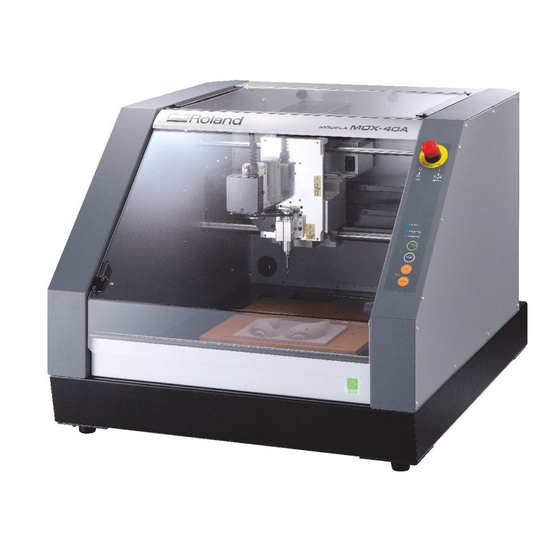
- Page 1 Roland MDX-40A MDX-40A Step-by-step guide Vol.1 Patrick Thorn...
- Page 2 "#$%&'()$*&# This guide is designed to demonstrate and help you understand the workflow of one side cutting with MDX-40A. If you read through these notes with your own model, you will understand the principles of operation. The SRP Player supplied with your machine, used with this guide is ver. 1.17. If your SRP Player is a different version, the specification and functions described may not appear the same.
-
Page 3: Table Of Contents
++++3-1+Preparation of the surface - levelling the base !!!!!!!!!!!!!!!! +++++++++Preparation of the base !!!!!!!!!!!!!!!!!!!!!!! +++++++++Installing the surface levelling tool !!!!!!!!!!!!!!!!!!! +++13-2+Setting the origin point of MDX-40A !!!!!!!!!!!!!!!!!!!!! +++++++++Setting the X- and Y- axis Origin Point !!!!!!!!!!!!!!!!! +++++++++Setting the Z-axis Origin Point !!!!!!!!!!!!!!!!!!!! -
Page 4: Think How Best To Cut The Object
Making a prototype using one side cutting only One side cutting, which creates a solid model by cutting MDX-40A+Step-by-step guide two separate components is the simplest method for Step1+One side cutting creating a model. -
Page 5: One Side Cutting
One side cutting With MDX-40A SRP Player... -
Page 6: Before You Start
Step 1. Before you start Choose your material and tools and think about the process required to complete the model. - Page 7 Sanmodur 7K is what is typically used in Roland DG Japan (local alternative modelling boards are also available). The MDX-40A was specifically developed to work with a wide range of synthetic and natural materials The following list describes the key characteristics of the most popular synthetic resin...
- Page 8 +++++For fast and efficient rough cutting, you should use the widest tool which will take away the majority of the unwanted material as quickly as possible. The largest diameter tool you can use with the MDX-40A is 6mm. However, this may be too wide for the geometry of smaller models and could leave too much material behind for a fine finishing tool to remove in holes, cavities, etc.
-
Page 9: The Workflow Of This Guide
Step1. Setting up The workflow of this guide Use a 6 mm diameter straight endmill. Surface This will give a level base for the material, ensuring cutting levelling the depths across the model are even. base Like the process of surface levelling the base, this cuts Surface level the model surface so that the thickness of the workpiece the modelling... -
Page 10: Before You Start Cutting
Step 2. Before you start cutting This step highlights preparation required, materials needed and the necessary equipment configuration required to commence the tutorial. - Page 11 Scraper (Long stainless steel kitchen spatulas are particularly good for this) [>$*&#GI MDX-40A Starter kit PGll the necessary equipment is included in the starter kit, comprising of modelling material, tool, parallel pins, guide and cutting data. Material size Workpiece for modelling (Sanmodur) 1 piece ,.R+S+,RR+S+2RTT...
-
Page 12: 1Preparation Of Pc And Software
2-2 Equipment Configuration /machine, driver, software0 Step 2+Before you start cutting MDX-40A retaining clamps for transportation Ensure the retaining clamps for shipment are removed from the MDX-40A +See User’s manual ++Chapter 2+Installation ++++.\.+Removing and Storing the Retainers Preparation of PC and software... - Page 13 <=$$*#B1(>1<`c1cIG@=% Start SRP Player From menu, select [File][Preferences], followed by [Modeling Machine] tab to display the choice of machines. K<elect MDX-40A L`emove the check next to Rotary axis unita Roland MDX-40Ab1 MChoose [ for printer From the menu, select [Option], [My Tools] to display the My Tool selection window "...
-
Page 14: 2-Setup Tasks. Cutting The Base And Workpiece
Step 3.+Setup Tasks. Cutting the Base and workpiece Preparation of the base Prepare the base workpiece to attach to the table. This is a sacrificial base. Base Ensure the base workpiece is bigger than the model workpiece. Clean the MDX40A table to remove any dust or swarf. - Page 15 2-3 Start the MDX-40A and VPanel Step 2+Before you start cutting Close the front cover Turn on the main power switch on the MDX-40A Turn on the sub power on the operation panel If you use Windows XP Select [Start] menu +d+[All program]+d+eRoland VPanel+for MDX-40Af1...
- Page 16 Step 3. Setup Tasks. Cutting the Base and workpiece Levelling the the base on the table, and preparing the model workpiece on the base.
- Page 17 It also means stronger adhesives such as glue can be used without damaging the table. What is surface levelling? Material thickness can vary throughout a sheet. Surface levelling creates a flat surface relative to the MDX-40A. Tool work...
-
Page 18: Installing The Surface Levelling Tool
<$=>1hi+<=$(>1CGAFAi1J($$*#B1$E=1^GA= G#'1D&%F>*=)= Installing the surface levelling tool Install the collet and tool appropriate for cutting. This tutorial requires the 6mm collet and 6mm straight end mill. Insert the tool from below. The tool extension length needs to exceed the cutting depth of the workpiece. -
Page 19: Setting The X- And Y- Axis Origin Point
Step 3. Setup Tasks. Cutting the h8]+<=$$*#B1$E=1&%*B*#1>&*#$1&_156789:; Base and workpiece Setting the X- and Y- axis Origin Point Draw diagonal lines from the corners of the base material. This will give you the centre of the material. Start jklmnl Change coordinate select (option [Ko in the diagram) to [User Coordinate System] pqser Coordinater This allows the user to set the origin in any position. -
Page 20: Setting The Z-Axis Origin Point
<$=>1hi+<=$(>1CGAFAi1J($$*#B1$E= ^GA=1G#'1D&%F>*=)= Setting the Z-axis Origin Point Place Z0 sensor on the base Refer to User’s manual Chapter 5 Appendix , 5-1 ‘Using the Z0 Sensor’ for details of how to use the Z0 sensor. Use cursor keys to move the tool to the position above the sensor. -
Page 21: Surface Levelling The Base
<$=>1hi+<=$(>1CGAFAi1J($$*#B1$E=1^GA= G#'1D&%F>*=)= Surface levelling the base From Windows [Start], choose [All programs] (or [Programs] then choose [SRP Player] SRP Player starts Select from menu [Option] [Surfacing] to show surface levelling display. Set the material to [Chemical wood (hard)]. - Page 22 For this guide, input [0.5mm] LJlicking [OK] button to start cutting If you open the front cover of the MDX-40A while cutting, the spindle and axes will lose power. You cannot continue cutting after an ‘emergency stop’...
-
Page 23: Preparation Of The Workpiece For Model And Surface Levelling
<$=>1hi+<=$(>1CGAFAi1J($$*#B1$E=1^GA= G#'1D&%F>*=)= Preparation of the workpiece for model and surface levelling Prepare the model workpiece using the size 120mm x 100mm x 30mm. Draw the diagonal lines as with the base to locate the centre origin. Apply double-sided tape to the entire area on the back of the workpiece. Double sided tape 2RTT... -
Page 24: 3-Creating The Cutting Tool Path
Step 4. Creating the tool path This step is about setting the method of each process that is common to each step of SRP Player. -
Page 25: Setting Of The Each Process
Step 4.+uvwxyz{ Setting each process KImport model data. Click[ File ][ Open ] from the top menu bar and open the file [Z0SENSOR_HOLDER.igs] from where it is saved on your computer. L1The dialog box is shown. Click [OK] and the model will be shown in the display. Check the model size and direction is correct. - Page 26 Step 4.+Create tool path Input the size of workpiece for model. The values in brackets ( ) represent the maximum model size in each axis. Your workpiece needs to exceed these measurements. Create cutting data (tool path) ++++++++ Click [Edit] button. Set up the rough cutting values.
- Page 27 Step 4.+Create tool path Set the margin KClick the ‘-’ position as below to expand the frame pallet. L+++++++Click [Automatic ], the automatic value is relative to the tool diameter. Click [Apply] Click [Close] What is the margin? The margin is an additional area around the model which is cut in order to allow the model circumference to be completed.
- Page 28 Step 4.+Create tool path Set the margin Click the ‘-’ position as below to expand the Modelling Form. Click [Automatic], the automatic value is relative to the tool diameter, plus a margin. Click [Apply] Click [Close] Generating cutting data KClicking [ ] generates the toolpaths sequentially.
-
Page 29: 4-Cutting The Model
Step 5. +Cutting the model This step is explains the cutting process. -
Page 30: Start Cutting
Open front cover and clean off the cutting waste. Start cutting If you open the front cover of the MDX-40A while cutting, the spindle and axes will lose power. You cannot continue cutting after an ‘emergency stop’ error. Just finished cutting... - Page 31 Step 5.+Cutting the model Remove the workpiece from the base using a scraper PCake care when removing the model. The scraper may damage the modelling board if excessive force is used. Gently slide the scraper between the base and model to loosen the double sided tape.
Need help?
Do you have a question about the MDX-40A and is the answer not in the manual?
Questions and answers