Table of Contents
Advertisement
Quick Links
Advanced Calibration
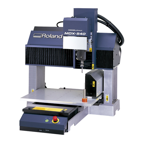
The purpose of this document is to assist users of the Roland MDX-540
fine tune the accuracy of their machine when using the 4th-axis option
(ZCL-540) – The following steps will assist users who observe any shifts
or offsets when performing double sided milling. We will cover two
sections:
• Section 1 - Setting Origins
• Section 2 – Manual Adjustments
Advertisement
Table of Contents

Related Manuals for Roland MODELA PRO II series


Summary of Contents for Roland MODELA PRO II series
- Page 1 Advanced Calibration The purpose of this document is to assist users of the Roland MDX-540 fine tune the accuracy of their machine when using the 4th-axis option (ZCL-540) – The following steps will assist users who observe any shifts or offsets when performing double sided milling. We will cover two sections: •...
- Page 2 Section 1 • Make sure to have your ZCL-540 user manual handy. • Begin the Y-origin sensor detection process. (pg 43-46) o Connect the sensor cable to the Z-origin sensor. (pg 43) o Install Y-origin sensor bar. (pg 44)
- Page 3 o Begin the “Detect Center of Rotation” process. (pg 45-46) • Set your Y and Z origins at the center of the A axis. (pg 47-49) o Open Base Point settings and use the “Set ___ at center of rotation” drop down menu to set the Y-origin. (pg 47)
- Page 4 o Connect the sensor cable to the Z-origin sensor and install a tool. (pg 48) o Open Base Point settings and use the “Set ___ at center of rotation” drop down menu to set the Z-origin. (pg 49)
- Page 5 • Set your X and A axis origins. (pg 50- 51) o Move your tool to the right of your work piece along the X- axis and set your X-origin using the “Set ___ here” drop down menu. (pg 50) o Move you’re Axis to a zero degree position and use the “Set ___ here”...
- Page 6 Section 2 • Once you have milled out your part using double index milling, check the “seam” of the part to find any adjustment values. (pg 53) • Observe what direction this shift occurs to determine what type of adjustment value you will use. For example, if the “top” of the part looks like it shifted upwards the Y direction, then your adjustment value will be negative.
- Page 7 • Divide your adjustment value by two and use “Set Base Point” in VPanel to correct your Y origin position. For example, if you had a measured adjustment value of 2mm then you would change the location of your Y origin by 1mm only. (pg 53) •...
- Page 8 • Divide your Z adjustment value by two and use “Set Base Point” in VPanel to correct your Z origin position. Again, if you measure an offset of 2mm, your adjustment will be 1mm. (pg 53) • Re-cut your part under these new origin settings to double check that your adjustments were correct.
Need help?
Do you have a question about the MODELA PRO II series and is the answer not in the manual?
Questions and answers