
Related Manuals for Roland monoFab SRM-20


Summary of Contents for Roland monoFab SRM-20
- Page 1 User’ s Manual Basics One Side Cutting Let’ s cut a piano( with included sample data) NC Code Maintenance...
-
Page 2: Getting Started
DGSHAPE Corporation assumes no responsibility for any direct or indirect loss or damage which may occur with respect to any article made using this product. http://www.dgshape.com/ Company names and product names are trademarks or registered trademarks of their respective holders. Copyright © 2014 - 2017 Roland DG Corporation Copyright © 2017 DGSHAPE Corporation... -
Page 3: Table Of Contents
Contents Scrap Boards ......... . 20 Getting Started . - Page 4 Contents STEP 2: Determine What to Do ......42 STEP 3 : Confirm the Command Set ..... 83 STEP 3 : Create the Cutting Data .
- Page 5 Contents of Cutting ..........130 Maintenance .
-
Page 6: Important Notes On Handling And Use
• Never needlessly touch anywhere inside the machine except for locations specified in this manual. Install in a suitable location. “http://startup.rolanddg.com” "Roland DG Start-up This machine becomes hot. • Never cover the ventilation holes with cloth, tape, or anything else. -
Page 7: Srm-20 Basics
SRM-20 Basics Important Notes on Handling and Use ... . . 6 Cutting Area ........21 Important Notes on Handling and Use . -
Page 8: The Feature Of This Machine
The Feature of this Machine ”SRM-20” Advanced cutting techniques that support a variety of materials A full array of software included This machine is capable of cutting a wide variety of materials including Exclusive CAM software is included so that you can start cutting chemical wood, acrylic, and ABS. -
Page 9: Part Names And Functions
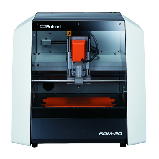
Part Names and Functions Front Front cover (Power) button Spindle head CAUTION Under no circumstances move the spindle unit or table with your hands. Doing so may cause a breakdown. • In this manual, the mechanisms around the spindle unit, including ”spindle head.”... -
Page 10: Side
Part Names and Functions Side Back ① ② Security label You will void the machine's warranty if the security label is removed. USB connector Power connector... -
Page 11: Vpanel (Operation Panel)
VPanel (Operation Panel) About VPanel Start VPanel It is the dedicated software for controlling this machine. Operation of this Procedure machine and various setup are performed using this software. ”http://startup.rolanddg.com” "Download Close the front cover. Press the (Power) button. The LED lamp starts flashing and it stays lit after initialization completes. - Page 12 VPanel (Operation Panel) ME M O Start “VPanel.” If VPanel is started with the machine's power turned off, the following screen ""VPanel Does Not Recognize the Machine" (p. 126) is displayed. Press the (power) button and click [Retry] to start VPanel. Windows 8 .1 Click in the...
-
Page 13: The Name And Function Of The Main Screen
VPanel (Operation Panel) The Name and Function of the Main Screen Name Function Name Function Selects the coordinate system for the coordinate values to display. • User Coordinate System : A coordinate system in which the location of the origin point can be freely changed [ON] and [OFF], rotation of a spindle is started and it •... - Page 14 VPanel (Operation Panel) Name Function Name Function Moves the spindle head to the center and moves the table to Adjusts the spindle speed. the very front. This position is called [View position]. ""Adjusting Rotation Speed of the Use this button when you want to change the cutting tool or Spindle"...
-
Page 15: Setup Dialog
VPanel (Operation Panel) Setup Dialog This dialog is displayed when setup is clicked. Modeling Machine Tab Display Function Select the appropriate command mode to match the software to be used. • [RML-1] : Select this command set when you want to use the software that was included with this machine • [NC Code] : Select this command set when you want to use NC codes ""NC Code Specifications"... - Page 16 VPanel (Operation Panel) Correction Tab Display Function The distance correction for the X-, Y-, and Z-axis can be set. Distance Adjustment Distance Adjustment : 99.5~100.5 NOTICE This setting affects the cutting accuracy. Exercise care when you specify this setting. If you are not confident in the value that you want to specify, we recommend that you do not specify this setting.
-
Page 17: Cut Dialog
VPanel (Operation Panel) Cut Dialog This dialog is displayed when cut is clicked. Display Function Output File List Output files are listed in the order they are output. Preview You can preview the selected file. Adds the file to output to the [Output File List]. -
Page 18: Quit Vpanel
VPanel (Operation Panel) Quit VPanel Click... -
Page 19: Cutting Tools
Cutting Tools Cutting Tool Types The SRM-20 supports the use of cutting tools with a shank diameter of up to 6 mm. * An optional collet is required when the shank diameter is 3 mm or 4 mm. ① ② ③... -
Page 20: Cutting Material / Scrap Boards
Cutting Material / Scrap Boards Material Types There are various kinds of the charges of a cutting material. Please use material properly by work what you want to cut. Chemical wood A material made of resin powder that has been hardened with an adhesive. It is available in various types by specific gravity. Compared to other materials, it is soft and easy to cut, but the thinner it is, the more easily it will break. -
Page 21: Cutting Area
Cutting Area Maximum Cutting Area of SRM-20 CAUTION Arrange the material, Jig, and the like so that they fit within the determined range. Anything extending beyond may strike moving parts. Be sure to observe this requirement, as failure to do so may result in damage to the workpiece or frame or malfunction of the machine. XY Direction . -
Page 22: Actual Size That Can Be Cut
Cutting Area Z Direction Spindle head bottom 71 mm * Work plate surface * A material thicker than this cannot be set. * The area that the material can be mounted on will vary due to the length of the attached cutting tool and the thickness of the scrap board. -
Page 23: Unit
Cutting Area Z Cutting Range by Changing the Position of the Spindle Unit There are two attachment positions (height) of a spindle unit. It uses properly with the length of a cutting tool, and the thickness of material. ""Changing the Position of a Spindle Unit" (p. -
Page 24: One Side Cutting
Easy Settings One Side Cutting The Flow of One Side Cutting . . . . . . . . . 25 MODELA Player 4 . . . . . . . . . . . . . . . . . . . 47 Cutting (One Side Cutting) . -
Page 25: The Flow Of One Side Cutting
The Flow of One Side Cutting The Flow of One Side Cutting "Piano.stl." In this manual, a procedure is explained by the method using If it does as a procedure, it can cut, as shown in the following figure . "Items Necessary for Cutting"... -
Page 26: Items Necessary For Cutting
Items Necessary for Cutting Software Applications Necessary For Sample Cutting ”http://startup.rolanddg.com” "Download SRP Player MODELA Player 4 "About SRP Player" (p . 29) "About MODELA Player 4" (p . 47) " " Virtual MODELA "STEP 3: Performing Cutting (when you are "STEP 3: Performing Cutting (when you are "... - Page 27 (When the SRP Player is installed on drive C) C:\ProgramData\Roland DG Corporation\SRPPlayer\Sample ( When the installation place of MODELA Player 4 is Drive C ) C:\ProgramData\Roland DG Corporation\MODELA Player 4\Sample "Piano . s tl" Data Size 70 mm 14 mm...
-
Page 28: Items To Prepare Yourself
Items Necessary for Cutting Items to Prepare Yourself ""Cutting Material / Scrap Boards" (p . 20) Material It is necessary to prepare larger size than cutting data . * The dimensions below are a reference size for the sample . For both SRP Player and MODELA Player 4, the values listed in this manual assume the following material size . -
Page 29: Srp Player
SRP Player About SRP Player This is a CAM software that imports general-use 3D data, (such as IGES, DXF (3D), or STL), and lets you easily prepare tool paths and output them to the SRM-20 . ”http://startup.rolanddg.com” "Download... -
Page 30: Starting Srp Player
SRP Player • Starting SRP Player Start from the Windows Start menu . Windows 8 . 1 To start SRP Player, do one of the following: • Double-click "START" Click on the screen. • Double-click an SRP file . Click [SRP Player] on the... -
Page 31: Setting Up The Output Device
SRP Player Procedure Setting Up the Output Device Configure SRP Player so that it can output data to the cutting machine . Connect the cutting machine to the computer with the USB cable and turn on the machine. IMPORTANT ""STEP 1 : Turning the Power On" (p . - Page 32 SRP Player Click Select the desired cutting machine and click MEMO The following dialog is displayed while the wizard is searching for cutting machines connected .
- Page 33 SRP Player Click Select the unit of length and click...
- Page 34 SRP Player Register the cutting tool. Click Select the check box next to the cutting tool you want to register and then This completes the settings . click...
- Page 35 [Preferences] dialog, click the [Cutting Machine] tab. Configure the settings . Procedure 2-1. Model Name: SRM-20 2-2. On the menu bar, click [File] [Preferences]. Spindle Unit: Standard 2-3. Table: Standard 2-4. Printer Name: Roland SRM-20 2-5. Click [OK] .
-
Page 36: The Name And Function Of The Tool Bar
SRP Player The Name and Function of the Tool bar Icon Function Detail Icon Function Detail Zooms in or out the model . Clicking the left mouse button shows an enlarged view of the model with the Simply saves the current project file without changing Save Zoom in/out point where you clicked at the center . -
Page 37: Display Help Dialog
SRP Player Display Help Dialog Quit SRP Player The basic operation and the processing procedure of SRP Player can be Click on the main screen. checked . Procedure On the menu bar, click [Help]. Click [Contents]. -
Page 38: Creating An Srp Player File
Creating an SRP Player File Flow Diagram "STEP 1: Determine the Size and Orientation of the Model" (p . 39) "STEP 2: Determine What to Do" (p . 42) "STEP 3 : Create the Cutting Data" (p . 43) "STEP 4: Preview the Result of Cutting" (p . - Page 39 ●〇〇〇 Creating an SRP Player File Procedure STEP 1: Determine the Size and Orientation of the Model Load an IGES, DXF (3D), or STL format file to set the size and orientation . Start SRP Player. ""Starting SRP Player" (p . 30) MEMO For details on how to change the settings, see the [Help] .
- Page 40 . Select the cutting data model ("Piano.stl"), and click [Open (O)] . Storage location of sample cutting data model C:\ProgramData\Roland DG Corporation\SRP Player\Sample (when the SRP Player is installed on drive C) ""Sample Cutting Data" (p . 27) MEMO...
- Page 41 Creating an SRP Player File Configure the size settings in the cutting data. Select the top surface of the cutting data model. The dialog displays the X, Y, and Z size settings for the currently open model . Turn up the face that will be ground first . You can change the size settings by entering new values into the X, Y, and Z boxes .
-
Page 42: Step 2: Determine What To Do
〇●〇〇 Creating an SRP Player File STEP 2: Determine What to Do Procedure Click Select any options that suit your needs. This example assumes that the following options are configured: • [Better surface finish] • [Model with many flat planes] •... -
Page 43: Step 3 : Create The Cutting Data
〇〇●〇 Creating an SRP Player File IMPORTANT STEP 3 : Create the Cutting Data Be sure to select a correct material . Selecting a wrong material would Procedure result in failure to correctly configure the cutting conditions . Click Select the material. Choose a workpiece material from the pull-down list . - Page 44 Creating an SRP Player File This example assumes that the following options are configured: Set the material size. X = 100 mm Set the material size so that it fits the cutting data model size and the size of the part you want to create . Y = 100 mm Z = 15 mm ""Items to Prepare Yourself"...
- Page 45 Creating an SRP Player File MEMO Create the cutting data (tool path). Clicking allows you to change the detailed settings of the cutting Click data . Once the cutting data (tool path) has been generated, [Uncreated] [Created] changes to under...
-
Page 46: Step 4: Preview The Result Of Cutting
〇〇〇● Creating an SRP Player File STEP 4: Preview the Result of Cutting Click The main view displays the preview . You can display a 3D preview of the result of cutting for simulation . You can also check a rough guide for the time that it will take for cutting . Procedure Click If the preview is satisfactory, proceed to... -
Page 47: Modela Player 4
MODELA Player 4 About MODELA Player 4 This is a CAM software that imports general-use 3D data, (such as IGES, DXF (3D), or STL), and lets you easily prepare tool paths and output them to the SRM-20 . ”http://startup.rolanddg.com” "Download... -
Page 48: Starting Modela Player 4
Windows 8 Right - click on the “START” screen. [All apps]. Click Click [MODELA Player 4] icon of [Roland MODELA Player Windows 7 [START] Click menu. Click [All Programs] (or [Program]) [Roland MODELA Player 4] [MODELA Player 4... -
Page 49: The Name And Function Of The Tool Bar
MODELA Player 4 The Name and Function of the Tool bar Icon Function Detail Icon Function Detail This command expands or reduces the size of the You can open either 3D data in IGES, DXF (3D), or STL object shown to fill the screen . When you're in split format, or existing project files . -
Page 50: Display Help Dialog
MODELA Player 4 Display Help Dialog Quit MODELA Player 4 The basic operation and the processing procedure of MODELA Player 4 can Click on the main screen . be checked . Procedure On the menu bar, click [Help]. Click [Contents]. -
Page 51: Creating A Modela Player 4 File
Creating a MODELA Player 4 File ●〇〇〇〇〇〇〇〇 Procedure STEP 1: Load the Cutting Data You can import a file in IGES, DXF (3D), STL, or MODELA Player (Ver . 3 or Start MODELA Player 4. later) format . Double - click ""Sample Cutting Data"... - Page 52 Creating a MODELA Player 4 File Click [File] - [Open], and select ”Piano.stl.” C:\ProgramData\Roland DG Corporation\MODELA Player 4\Sample ( When the installation place of MODELA Player 4 is Drive C ) ""Sample Cutting Data" (p . 27) MEMO The change of a display screen can be performed by on the tool bar .
-
Page 53: Step 2 : Set The Machine Selection
Configure MODELA Player 4 so that it can output data to the cutting machine . 2-2. Command Set : [RML-1] Spindle Unit : [Standard] 2-3. [Roland SRM-20] Printer Name : IMPORTANT 2-4. Click [OK] . Unless a machine setup is performed, a right setup or output cannot be performed . Procedure... -
Page 54: Step 3 : Set The Origin Point Of The Model And Orientation
〇〇●〇〇〇〇〇〇 Creating a MODELA Player 4 File STEP 3 : Set the Origin Point of the Model and Orientation Origin point of the Model / Origin point • Origin point of the model : XY origin point set up on cutting data ( The origin point on the data of MODELA Player 4 ) •... - Page 55 Creating a MODELA Player 4 File Procedure Set the origin point of the model. “Origin” Click the tab, select the origin position . Click [Model]. “Piano.stl” : Center of the model [OK] [Selected Top Surface]. “Piano.stl” : Following figure [OK]...
- Page 56 Creating a MODELA Player 4 File Set the Size of Cutting Data The size of cutting data can be checked at the lower right on the main screen . Cutting data size can be changed on MODELA Player 4 to arrange data size with material .
-
Page 57: Step 4 : Set The Material
〇〇〇●〇〇〇〇〇 Creating a MODELA Player 4 File STEP 4 : Set the Material Select the material. Choose a workpiece material from the pull-down list . Select the quality of the material . Set the type of prepared material . ""Material Types" (p . -
Page 58: Step 5 : Set The Margin
〇〇〇〇●〇〇〇〇 Creating a MODELA Player 4 File STEP 5 : Set the Margin Select the margin setting. “Piano.stl” [Automatic] [OK] Margin Make settings for the space around the model to provide approach paths for the cutting tool . Procedure [Modeling Form]. - Page 59 Creating a MODELA Player 4 File The Cutting Area is Different Depending on the Margin Settings <When no-margin (0 mm) is set up > <When margin ( arbitrary numbers ) is set up> The preview when you set The preview when you set margin margin "0 mm."...
-
Page 60: Step 6 : Set The Surface Leveling Process Of Material
〇〇〇〇〇●〇〇〇 Creating a MODELA Player 4 File STEP 6 : Set the Surface leveling Process of Material Surface leveling of material Leveling eliminates unevenness in the surface of a material to create a work plane that is parallel with the cutting plane along which the cutting tool moves . Cutting plane along which the cutting tool... - Page 61 Creating a MODELA Player 4 File Procedure Set the type of process. Select [Surfacing], then click [Next] . Create the surface leveling process of material. [New Process] . Click...
- Page 62 Creating a MODELA Player 4 File Set the cutting surface. Select the cutting tool. Check that the [Top[+Z]] is selected and click the [Next] . “Piano.stl” [3 mm Square] [Next] "3 mm Square" is not displayed on the screen ""STEP 2 : Set the Machine Selection"...
- Page 63 Creating a MODELA Player 4 File Set the area and depth for surface leveling. 5-1. Set the surface level area . “Piano.stl” [Inside modeling form] 5-2. Set the depth of surface leveling . “Piano.stl” ”0.5” [Set Z0 after surface leveling] 5-3.
- Page 64 Creating a MODELA Player 4 File Set the tool path. Tool Path “Piano.stl” [Scan Lines] [Next] This is the path that is drawn when the cutting tool cuts into the material . Depending on the CAM software used, there are many tool paths for each application . MODELA Player4 has the following tool paths .
- Page 65 Creating a MODELA Player 4 File Set the cutting parameters. Enter a name for this process and create the tool path. “Piano.stl” : No change [Next] “Piano.stl” [Right Now] [Finish] The appropriate conditions are displayed as the initial values from the selected cutting tool settings and material settings .
- Page 66 Creating a MODELA Player 4 File The tool path is created . And the process which is created is displayed . MEMO A double click of each setting item of a process display a setting screen . The settings can also be changed after the process is created .
-
Page 67: Step 7 : Confirm The Cutting Preview
〇〇〇〇〇〇●〇〇 Creating a MODELA Player 4 File Procedure STEP 7 : Confirm the Cutting Preview You can view in 3D and simulate the tool path and cutting tool movement [Cutting Preview]. Click that were set in MODELA Player 4 using the included Virtual MODELA application software . - Page 68 Creating a MODELA Player 4 File Virtual MODELA starts . When the following screen is displayed, click [OK]. Estimated cutting time MEMO For details on the operation methods, please refer to the help . [Help] [Contents] The help can be displayed with on the menu .
-
Page 69: Step 8 : Set The Roughing Process
〇〇〇〇〇〇〇●〇 Creating a MODELA Player 4 File Procedure STEP 8 : Set the Roughing Process Create the roughing process. Roughing [New Process] . Click This task cuts a rough outline and leaves the detailed portions . This is an important process for reducing cutting time and increasing the efficiency of the finishing process . - Page 70 Creating a MODELA Player 4 File Set the type of process. Set the cutting surface. Select [Roughing], then click [Next] . Check that the [ Top[+Z] ] is selected and click the Next] .
- Page 71 Creating a MODELA Player 4 File Select the cutting tool. Set the area and depth for roughing. “Piano.stl” [3 mm Square] [Next] "Piano.stl" [All] [Next] [All] When is selected, the values are automatically entered .
- Page 72 Creating a MODELA Player 4 File Set the tool path. Set the cutting parameters. ""Tool Path" (p . 64) “Piano.stl” : No Change [Next] “Piano.stl” [Contour][Up Cut] [Next] The appropriate conditions are displayed as the initial values from the selected cutting tool settings and material settings . We recommend using the settings as they are (recommended values) except in situations where you want to make a particular adjustment .
- Page 73 Creating a MODELA Player 4 File The tool path is created . And the process which is created is displayed . Enter a name for this process and create the tool path. “Piano.stl” [Right Now] [Finish] MEMO A double click of each setting item of a process display a setting screen .
-
Page 74: Step 9 : Set The Finishing Process
〇〇〇〇〇〇〇〇● Creating a MODELA Player 4 File Procedure STEP 9 : Set the Finishing Process Create the finishing process. Finishing Click [New Process] . The finishing process cuts the finely detailed portions according to the shape of the data . A cleaner finish can be obtained by effectively using the types of cutting tools . - Page 75 Creating a MODELA Player 4 File Set the type of process. Select the cutting tool. Select [Finishing] and click Next] . “Piano.stl” [3 mm Square] [Next] Set the cutting surface. Check that the [Top[+Z] ] is selected and click the [Next] .
- Page 76 Creating a MODELA Player 4 File Set the area and depth for finishing. Set the tool path. "Piano.stl": [All] [Next] ""Tool Path" (p . 64) "Perfume.stl": [Contour Lines], Cut], [Optimized Pitch] [Next] [All] When is selected, the values are automatically entered .
- Page 77 Creating a MODELA Player 4 File Set the cutting parameters. Enter a name for this process and create the tool path. “Piano.stl” : No Change [Next] “Piano.stl” [Right Now] [Finish] The appropriate conditions are displayed as the initial values from the selected cutting tool settings and material settings .
- Page 78 Creating a MODELA Player 4 File Save the Created Cutting Data The tool path is created . And the process which is created is displayed . Click the [File] [Save as...], you can save the cutting data created by MODELA Player 4 . ( Extension : mpj ) ""The Name and Function of the Main Screen"...
-
Page 79: Preparing The Machine
Preparing the Machine Flow Diagram “STEP 1 : Turning the Power On” (p. 80) ※ “STEP 2 : The Machine Run-in” (p. 81) ※ “STEP 3 : Confirm the Command Set” (p. 83) “STEP 4 : Attach the Cutting Tool” (p. -
Page 80: Step 1 : Turning The Power On
●〇〇〇 Preparing the Machine STEP 1 : Turning the Power On Procedure Close the front cover. Press the (Power) button. The LED lamp starts flashing and it stays lit after initialization completes. -
Page 81: Step 2 : The Machine Run-In
〇●〇〇 Preparing the Machine Procedure STEP 2 : The Machine Run-in If a material, or cutting tool is mounted on the machine, remove it. When the machine must be run-in Start VPanel. • When the machine is first set up •... - Page 82 Preparing the Machine Click [Confirm] tab. Click [Start] “Idling.” * Required time : Approx. 10 minutes [OK] [Maintenance] When operation is completed, click and close a screen.
-
Page 83: Step 3 : Confirm The Command Set
〇〇●〇 Preparing the Machine STEP 3 : Confirm the Command Set Select the suitable command set. “Piano.stl” [RML-1] [OK] Select the appropriate command mode to match the software to be used. "“Command Set” (p. 15) NC Code file outputting "“NC Code Specifications”... -
Page 84: Step 4 : Attach The Cutting Tool
〇〇〇● Preparing the Machine STEP 4 : Attach the Cutting Tool Aim of the cutting tool installation Select a cutting tool matched to the purpose. If you use the tools selectively according to the work process such as “Roughing” “Finishing” and the design, you can obtain an even cleaner finish. - Page 85 Preparing the Machine Tighten the set screw with hexagonal wrench. Loosely tighten the collet with cutting tool. Insert the collet, and then loosely tighten Click [View] of VPanel. A spindle head moves to a center and a table moves to the front. Fully tighten the collet.
- Page 86 Preparing the Machine When changing to a cutting tool with the same shank diameter When changing to a cutting tool with a different shank diameter CAUTION Do not touch the tip of the cutting tool with your fingers. Procedure Doing so may result in injury. Remove the collet from machine.
-
Page 87: Cutting (One Side Cutting)
Cutting (One Side Cutting) Flow Diagram “STEP 1 : Attach the Material to the Table” (p. 88) “STEP 2 : Set the Origin Point” (p. 89) “STEP 3: Performing Cutting (when you are using SRP Player)” (p. 93) “STEP 3: Performing Cutting (when you are using MODELA Player 4)” (p. -
Page 88: Step 1 : Attach The Material To The Table
●〇〇〇〇 Cutting (One Side Cutting) STEP 1 : Attach the Material to the Table Click [View] of VPanel. Procedure Mark the location that will be the origin point of the material. Attach the material to the table. MEMO Stick double-stick tape on the material. If you mount it in a position in the front, the work will be easier. -
Page 89: Step 2 : Set The Origin Point
〇●〇〇〇 Cutting (One Side Cutting) 1. Prepare to set the origin point STEP 2 : Set the Origin Point [Machine Coordinate System] Select on the VPanel. About Origin Point Before you start cutting, you must set the origin point. When you cut with this machine, you need to set the X, Y, and Z origins. The X and Y origins are determined by the cutting data and the location of the material. - Page 90 Cutting (One Side Cutting) 2. Set the origin point Check that XYZ is “0.00 mm.” [X][Y] Click cursor button, move right above the origin point which put the mark by STEP1. "“Direction of Y axis using keypad” (p. 15) Select[User Coordinate System], check that XYZ is “0.00 mm.”...
- Page 91 Cutting (One Side Cutting) Click the [- Z] cursor button to approximate the tip of the cutting Loosen the set screw, and then adjust the cutting tool so that its tip tool to the surface of the material as much as possible. contacts the surface of the material.
- Page 92 Cutting (One Side Cutting) Tighten the cutting tool in place again with the set screw. Click [X/Y][Z] of set origin point. Click [YES]. “0.” Confirm that the coordinates have all become...
-
Page 93: Player)
〇〇●〇〇 Cutting (One Side Cutting) STEP 3: Performing Cutting (when you are using SRP Player) Leveling the Material Surface MEMO Procedure If you are using MODELA Player 4 rather than SRP Player, proceed to “STEP On the menu bar of SRP Player, click [Options] ... - Page 94 Cutting (One Side Cutting) On the dialog that appears, configure leveling cutting range, Make sure that the desired tool and origin position are correctly set depth, and other settings. up and then click This example assumes that the following options are configured: •...
- Page 95 Cutting (One Side Cutting) Performing Cutting Check if the cutting tool is installed as shown in the dialog and then click Procedure Open the pallet. Click...
- Page 96 Cutting (One Side Cutting) Relation between the origin point of the model and the origin point Select the surface of the material and then click Set up the origin point of the model and the origin point of the machine to become the same position.
- Page 97 Cutting (One Side Cutting) Click The machine begins cutting. A dialog appears that shows what is being output and the progress of machining.
-
Page 98: Step 3: Performing Cutting
Cutting (One Side Cutting) Cutting Only the Selected Process Procedure Open pallet. Click Click the process you do not need. Click [Enable/Disable Cutting]. Repeat steps 3 and 4 to disable all the unnecessary processes. Only the colored processes will be output. Click Start the cutting process using the same procedure as for the normal cutting process. - Page 99 Cutting (One Side Cutting) Completing Cutting Click...
-
Page 100: Step 3: Performing Cutting
〇〇●〇〇 Cutting (One Side Cutting) The points to be checked before cutting STEP 3: Performing Cutting (when you are using MODELA Player 4) Check the following thing before starting cutting. If there are problems with MEMO any of these, the cutting material may be wasted or the machine may be damaged. - Page 101 Cutting (One Side Cutting) Cutting Only the Selected Process Click [OK]. Select the unnecessary process and click [Enable/Disable Cutting]. Only the orange-colored processes will be output. Click [Continue]. “Processed items,” In the outputting contents is displayed.
-
Page 102: Step 4 : Remove Processed Material
〇〇〇●〇 Cutting (One Side Cutting) STEP 4 : Remove Processed Material MEMO The piano can be cut out by making the depth of the cutting Depending on the settings configured on VPanel, the power may deeper than the cutting data. (* A scrap board is necessary. automatically turn off when a certain period of time elapses with the “Scrap Boards”... -
Page 103: Step 5 : Turning The Power Off
〇〇〇〇● Cutting (One Side Cutting) STEP 5 : Turning the Power Off Push (Power) button. A LED lamp lights off. After cutting, clean the cutting waste certainly. "“Cleaning after Cutting Operation Ends” (p. 119) -
Page 104: Operations Available During Cutting
Cutting (One Side Cutting) Operations Available during Cutting Cleaning during an extensive cutting operation (X,Z-axis) Pausing / Resuming If cutting waste accumulates during an extensive cutting Click [Pause] of VPanel. The display of a button changes to [RESUME]. Click operation, the machine’s operation may be hindered, [RESUME] to resume. - Page 105 Cutting (One Side Cutting) Cancel the Cutting Caution of Cutting After an Emergency Stop and a Shutdown When you want to cancel the cutting, click the [Cancel] of VPanel. If an emergency stop or an emergency shutdown occurs during cutting, Outputting data is deleted .
- Page 106 Cutting (One Side Cutting) Adjusting the Feed Rate and Spindle Speed During Cutting The feeding speed and number of rotations of a spindle can be adjusted during cutting by VPanel. Adjusting Cutting Speed (Override) This works for the speed of cutting tool movement when cutting the workpiece.
-
Page 107: Nc Code
NC Code NC Code Setting . . . . . . . . . . . . . . . . . . . . . . . . . . . . . . 108 NC Code Setting Dialog . -
Page 108: Nc Code Setting
NC Code Setting NC Code Setting Dialog This dialog is displayed when Settings is clicked on the VPanel . NC Code Tab Display Function This selects the type of correction (offset) for the tool diameter . The locus through which the tool passes differs according to the offset type . For more information, refer to the "NC Code Reference Manual."... - Page 109 NC Code Setting Tool-Diameter Offset Tab Display Function Offset This sets the tool-diameter offset for NC codes . If the tool-diameter offset is not set by G10, these are used .
-
Page 110: Test Cut Dialog In Nc Code
NC Code Setting Test Cut Dialog in NC Code For a cutting data file written in NC code, test output is possible on the VPanel to check it for the presence of mistakes (bugs) . "“Cut Dialog” (p . 17) Test output conditions • When the current command set is “NC code.”... -
Page 111: Nc Code Specifications
NC Code Specifications List of Settings Related to NC Code The following list contains the settings related to interpreting and executing NC code that can be performed on the machine . Use NC programs to perform all other settings . "Separate volume “NC Code Reference Manual”... -
Page 112: Items Related To The Mechanical Specifications
NC Code Specifications Tool-Diameter Offset Value [Setup] [NC Code setting] . Then set this value on the [Tool-diameter Offset] On the VPanel, click and then tab . You can also use NC programs to set the G10 coordinate system . Tool-Diameter Offset Type (G41, G42) [Setup] [NC Code... -
Page 113: Interpretations Of Nc Code Omissions
NC Code Specifications Tool-Diameter Offset (G41, G42) The ranges of the G41 and G42 parameters are as follows . Parameter : Number Function : Offset number Acceptable range : 0 to 8 Valid range : 0 to 8 Feed Rate (F) The range of the F parameter is as follows . - Page 114 NC Code Specifications Workpiece Coordinate System (G54 to G59) If these codes are omitted, the machine assumes workpiece coordinate system 1 (G54) at all times . Dimension (G90, G91) If these codes are omitted, the machine assumes absolute (G90) at all times . Feed Rate (F) If the F code is omitted, the feed rate is set to 120 mm/min (4 .72 inches/min) .
-
Page 115: Word List
NC Code Specifications Word List The words supported by this machine are listed in the following chart . For details on each word, see the "NC Code Reference Manual." Preparation Feature (G feature) Continuation Group Name Function Word Continuation Function Group Name Function Word... - Page 116 NC Code Specifications Support Features (M feature), Feed Feature (F feature) Function Start Function Continuation S a m e T i m e a s t h e O p e r a t i o n After the Operation Specified by Word Function Held until the Command Is...
-
Page 117: Maintenance
Maintenance Important Notes on Care and Maintenance . . . . . . . 118 The Power Turns Off After Cutting Ends . . . . . . . . . . . . . . . . . . . . . 131 The Cutting Tool Does Not Reach the Material . -
Page 118: Important Notes On Care And Maintenance
Important Notes on Care and Maintenance WARNING Never use a pneumatic blower. This machine is not compatible with a pneumatic blower. Cutting waste may get inside the machine and cause fire or electrical shock. WARNING Never use gasoline, alcohol, thinner, or any other flammable material for cleaning. Doing so may cause fire. WARNING Always unplug the power cord when attaching or removing parts and optional parts. Attempting such operations while the machine is connected to a power source may result in injury or electrical shock. WARNING When using a dust collector to collect cutting waste, exercise caution to prevent fire and explosions of dust. Using an ordinary dust collector to collect fine cuttings may lead to fire or explosions. Contact the dust collector manufacturer to check whether the dust collector can be used to collect cutting waste. If you cannot confirm that it is safe to use the dust collector, use a brush or similar tool to collect cutting waste. Do not use the dust collector. CAUTION Caution: high temperatures. -
Page 119: Cleaning After Cutting Operation Ends
Cleaning after Cutting Operation Ends Procedure Cleaning the X-/Z-Shafts Remove the material that has finished being cut and the cutting After processing is completed, please be sure to remove cutting waste . It tool. becomes a cause of malfunction . When the material cannot be removed well, it removes using wooden spatulas etc . - Page 120 Cleaning after Cutting Operation Ends Push ( Power ) button. Brush off the cutting waste that has fallen on the X- and Z-shafts Turn off the machine’s power . and around the table using a commercially available brush. Commercially brush Z shaft X shaft WARNING...
- Page 121 Cleaning after Cutting Operation Ends Brush the cutting waste down into the dust tray from the positions Remove the cutting waste that has collected in the dust tray. indicated on the figure below.
-
Page 122: Replacement Of The Consumable Parts
There are various consumable parts in this machine . To request consumable parts, visit the DGSHAPE Corporation website . (http://www .dgshape .com/) • If you have any questions, refer to the DGSHAPE Corporation website (http://www .dgshape .com/) . If you cannot access the website, contact your authorized Roland DG Corporation dealer . • Use the specified consumable parts . -
Page 123: Confirm The Total Spindle Motor Rotation Time
Replacement of the Consumable Parts Procedure Confirm the Total Spindle Motor Rotation Time The total time of rotation of spindle motor can be checked by VPanel . You On the VPanel, click at the upper left of a screen, and click can reference for getting to know replacement time . -
Page 124: Run In The Spindle
Replacement of the Consumable Parts Run in the Spindle Move the slider to the center. • Guide : Approx . 5 minutes After replacing the spindle unit and spindle motor, run in the spindle . Failure to run in the spindle may result in unstable spindle rotation . Procedure Move the slider to [Low]... -
Page 125: Replacement The Table
Replacement of the Consumable Parts Replacement the Table Fit the new table into the screw notches. Procedure Remove a material and cutting tool mounted on the machine. Click [ View ] of VPanel. Pull down the front guard and loosen the screws at the positions shown in the figure. -
Page 126: What To Do If
What to Do If . . . Initialization Is Not Performed / Initialization Fails VPanel Does Not Recognize the Machine Is a Front Cover Open? Has Initialization Been Completed? When starting the machine, make sure that the front cover is closed . For Has initialization been completed? Before you start VPanel, first switch on the safety, initialization is not performed when a cover remains open at startup . -
Page 127: Operations Are Ignored
What to Do If . . . Operations Are Ignored Is the Cable Connected? Is a Large Amount of Cutting Waste Present? Check whether the connector cable has come loose . Please use the included Clean away any cutting waste . Clean the area around the spindle head cable . -
Page 128: Wrong
. Even if it replaces spindle motor/unit, when not being repaired Contact your authorized Roland DG Corporation dealer where you purchase Is a Front Guard Pull Down ? the machine . -
Page 129: Abnormal Cutting Is Performed
What to Do If . . . Abnormal Cutting is Performed The Origin is Misaligned Is a Large Amount of Cutting Waste Present? Is the Correct Workpiece Coordinate System Selected? Clean away any cutting waste . Clean the area around the spindle head In the NC program, there are six coordinate systems . -
Page 130: The Cutting Results Are Not Attractive
There will be bad influence on the cutting result if the material is not firmly attached to the table or scrap board . Increase the number of double-stick [ Roland SRM-20 ] dialog is displayed. tape and fix firmly . -
Page 131: The Power Turns Off After Cutting Ends
What to Do If . . . The Power Turns Off After Cutting Ends The Driver Cannot Be Installed If installation quits partway through, or if the wizard does not appear when Is the Auto-Power-Off Function Set Up? you make the connection with a USB cable, take action as follows . - Page 132 What to Do If . . . In the “Confirm Device Uninstall” dialog box, select the [Delete Click [Show hidden devices] on the [View] menu. the driver software for this device]. check box, and then click [OK] Double-click [Printers] [Other devices] in the list.
-
Page 133: Uninstalling The Driver
What to Do If . . . Uninstalling the Driver When the “User Account Control” dialog box appears, click [Continue]. The driver’s installer starts . Follow the appropriate procedure below to uninstall the driver . Click [Uninstall]. Select the machine that you want to uninstall, and then click [Start] . Windows 8/8 . - Page 134 What to Do If . . . Select the machine s driver that you want to uninstall, and then click [Uninstall]. ’ When a message prompting you to confirm that you want to uninstall the driver appears, click [Yes]. Start Windows Explorer to open the drive and folder where the driver is located.(*Note) “SETUP64.EXE”...
-
Page 135: Abnormal Noise Occurs
What to Do If . . . Abnormal Noise Occurs 1. Apply the Grease Is It the Replacement Time of a Spindle Unit? Spindle unit is consumable . If it is used for 1000 hours or more, replace for a If a material, or cutting tool is mounted on the machine, remove it. - Page 136 What to Do If . . . 2. Run in the machine. Push ( Power ) button. Turn off the power of the machine . Run in the machine. "“STEP 2 : The Machine Run-in” (p . 81) WARNING Perform this task with all power switches left switched off.
- Page 137 Click to end on the way . If an unusual noise occurs or if it stops midway, apply grease again . If the condition does not improve, contact your authorized Roland DG Corporation dealer where you purchase the machine .
-
Page 138: Changing The Position Of A Spindle Unit
What to Do If . . . Changing the Position of a Spindle Unit Remove the Spindle Unit "“Z Cutting Range by Changing the Position of the Spindle Unit” (p . CAUTION Never touch the spindle unit immediately after machining. Doing so may cause burns. Procedure If there is cutting waste inside the front cover, remove it. - Page 139 What to Do If . . . Switch off the power and unplug the AC adapter from the power Remove the spindle unit. outlet. 5-1. Remove the screws in the locations shown in the figure using a hexagonal wrench . (2 places) 5-2.
- Page 140 What to Do If . . . The attachment position of a spindle "“Z Cutting Range by Changing the Position of the Spindle Unit” (p . 23) High position Screw Pin hole position Screw hole...
-
Page 141: Initializing This Machine's Settings
What to Do If . . . Initializing This Machine's Settings [ Confirm ] Click tab. Procedure On the VPanel, click at the upper left of a screen, and click [Maintenance]. [ Clear ] Click of Settings. -
Page 142: Displaying This Machine's Settings
What to Do If . . . Displaying This Machine's Settings [ Confirm ] Click tab. You can use the VPanel to display the settings of this cutting machine as text, and also to save the settings as a text file . This feature is useful when you want to share settings between users, when you need to provide setup information when you request repairs for a malfunctioning machine, or under similar circumstances . -
Page 143: Confirm The Version Information
What to Do If . . . Confirm the Version Information Sample files are not found The folder that contains sample cutting data may not be visible depending VPanel on the settings of your computer . To display the folder that contains sample cutting data, use the following steps: Procedure Procedure... -
Page 144: Responding To Error Messages
- Y-Limit switch not found . Switch off the machine's power and contact your authorized - Z-Limit switch not found . Roland DG Corporation dealer where you purchase the machine . - The NVRAM could not be accessed . Operation cannot be continued . - Page 145 Responding to Error Messages Message Responding Page "“The Spindle Doesn’t Rotate Turn off power of the machine . The spindle rotation is stopped . / Spindle Rotation Speed Is The cutting may have exceeded the capacity of the - The spindle motor experienced an overcurrent . Wrong”...
-
Page 146: Appendix
Appendix Specifications . . . . . . . . . . . . . . . . . . . . . . . . . . . . . . . . 147 External View . -
Page 147: Specifications
Specifications External View Front Side Unit : mm Unit : mm 422.7... - Page 148 Specifications Side Cover Side Cover Plate Unit: mm Unit: mm 145.9 56.5 168.9 65.5 2-R1784.5 210.9 4-R2...
- Page 149 Specifications Machine Interior Side Face Unit: mm...
- Page 150 Specifications Spindle Head Carriage Unit: mm 42.4 Spindle Unit Mounting Face 49.7...
-
Page 151: Main Specifications
Specifications Main Specifications SRM-20 Cuttable material Resins such as chemical wood and modeling wax (metal not supported), substrates for machining X, Y, and Z operation strokes 203 .2 (X) x 152 .4 (Y) x 60 .5 (Z) mm ( 8 (X) x 6 (Y) x 2 .38 (Z) inches ) Distance from collet tip to table Maximum 130 .75 mm ( 5 .15 inches) Table size... - Page 152 FA01218 R4-171006...
Need help?
Do you have a question about the monoFab SRM-20 and is the answer not in the manual?
Questions and answers