Table of Contents
Advertisement
Quick Links
Advertisement
Table of Contents

Subscribe to Our Youtube Channel
Related Manuals for HeartWare Ventricular Assist System


Summary of Contents for HeartWare Ventricular Assist System
- Page 1 HeartWare Ventricular Assist System ® Instructions For Use...
-
Page 3: Table Of Contents
INDICATIONS AND CONTRAINDICATIONS FOR USE ............1 WARNINGS ........................1 PRECAUTIONS ........................ 2 POTENTIAL COMPLICATIONS ..................3 SYSTEM COMPONENTS OVERVIEW ................4 ® 6.1 HeartWare Ventricular Assist System ..................4 ® 6.2 HeartWare Controller ......................4 6.3 HeartWare ® Monitor ......................4 ®... - Page 4 HeartWare 14.0 SURGICAL IMPLANT PROCEDURE ................22 14.1 HeartWare Ventricular Assist System Setup ..............23 ® 14.2 HVAD Pump Pre-Implant Test ..................24 ® 14.3 Outflow Graft Attachment ....................25 14.4 Pump Implantation Preparation ..................25 14.5 Left Ventricle (LV) Apex Cannulation .................. 25 14.6 Outflow Graft Anastomosis ....................
-
Page 5: Introduction
® Ventricular Assist System is intended for use under the direct supervision of a licensed healthcare practitioner or by personnel trained in its proper use. Clinical users include physicians, registered nurses, perfusionists and biomedical engineers. Implant of the device must be performed by a qualified cardiac surgeon trained by HeartWare-authorized personnel. -
Page 6: Precautions
Pump explant the percutaneous driveline is not sterile; therefore ensure that the driveline does not contaminate the sterile field. DO NOT drop the controller or other equipment. Dropping the controller could cause sudden stoppage of the pump. Dropped equipment should be reported to HeartWare and inspected. -
Page 7: Potential Complications
Never clean the monitor or battery charger with the power on. DO NOT use alcohol or detergent on the monitor display. Gently wipe the display with a soft, lint free cloth. The monitor’s internal battery should be fully charged prior to patient use. Do not attempt to repair or service any components of the HeartWare System. If HeartWare System equipment malfunctions, contact HeartWare. -
Page 8: System Components Overview
6.2 HeartWare Controller ® The controller (Figure 3) is a microprocessor unit that controls and manages HeartWare System operation. It ® sends power and operating signals to the blood pump and collects information from the pump. The percutaneous driveline is connected to the controller, which must always be connected to two power sources using an AC adapter or DC adapter and/or rechargeable batteries. -
Page 9: Equipment For Implant
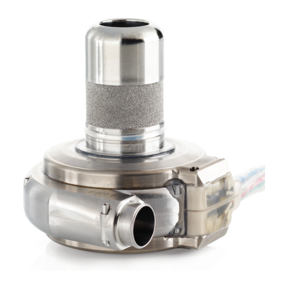
Viscosity is calculated from the patient’s hematocrit. To obtain the most accurate estimate of blood flow, the patient’s hematocrit must be entered into the HeartWare monitor. Flow estimation should be used as a trending tool only, 1. Inflow Cannula as it cannot adapt to changing fluid conditions (see Section 7.3.1 “Flow Estimation”). -
Page 10: Physiological Control Algorithms
5% or greater. NOTE: HeartWare recommends that hematocrit be updated in the monitor whenever hematocrit changes by 5% or more. The valid range of estimated blood flow is -2 to 10 L/min. The table below shows monitor and controller display messages and what they mean. -
Page 11: Lavare Cycle
1800-4000 RPM during the low and high speed portions of the cycles. This cycle is repeated periodically every 60 seconds. The Lavare Cycle is depicted in the figure below. High Speed The Lavare Cycle can be enabled or disabled by the clinician via the HeartWare Monitor. It ®... -
Page 12: Using The Heartware ® Monitor
8.1 Selecting a Language for the Monitor Figure 14: The Monitor Power Buttons (1 & 2) The monitor is designed to provide a user-friendly way to monitor and control the HeartWare ® System. The monitor displays information selected by the user. To choose a language for the monitor, go to the System Screen. The System Screen is accessed by pressing the HVAD Pump Icon (Figure 15). -
Page 13: Clinical (Home) Screen
Pump Icon. ® The System Screen is password-protected. HeartWare will provide the clinician with a password. The dialog box (Figure 27) is used to enter the numeric password. User access is timed out after 11 minutes of non-use. Figure 24: Alarm Log... -
Page 14: Speed/Control Tab
The maximum storage for each controller is 3000 entries, which equates to approximately 31 patient days. A USB flash drive can be used intermittently to download data. Figure 32: Implant Date screen HeartWare Ventricular Assist System ®... -
Page 15: Vad Tab
Ventricular Assist System 8.6.2.2 VAD Tab The VAD tab (Figure 33) is used to enable or disable the Lavare Cycle and Suction Response and to enter the HVAD Pump serial ® number. “Fixed” mode (manual entry of pump speed) is the only mode currently available, therefore this button is disabled. -
Page 16: Monitor Tab
Touchscreen: Use this button to initiate touch screen calibration for the monitor. The monitor will only initiate the ◗ ◗ calibration sequence if the controller is NOT connected to the monitor. Figure 42: Monitor tab HeartWare Ventricular Assist System ®... -
Page 17: Alarm Settings Tab
Ventricular Assist System 8.6.3 Alarm Settings Tab The Alarm Settings tab (Figure 43) is used to set the Low Flow Alarm and High Power Alarm thresholds. Both flow and power are time averaged values not instantaneous values. The Low Flow Alarm threshold may be set from 1 L/min to 9.9 L/min in 0.1 L/min increments. -
Page 18: Monitor Shut Down
To completely power off, you must press AND HOLD the power button until the screen shuts off. b. Press “No” to return to the program. Figure 47: Confirming monitor shutdown 9.0 USING THE HEARTWARE CONTROLLER ® 9.1 Connector Layout There are four connectors, two on either side of the controller (Figure 48). -
Page 19: How To Change The Controller
Disconnect both power sources from the original controller. The controller will be turned off and all alarms silenced. Slide the white driveline cover up to cover new controller’s silver connector (Figure 53). Contact HeartWare to obtain a new backup controller. WARNING Keep a spare controller and spare fully charged batteries available at all times in case of an emergency. -
Page 20: Using The Heartware ® Batteries
HeartWare 10.0 USING THE HEARTWARE BATTERIES ® The batteries (Figure 54) contain lithium ion cells to power the HVAD ® Pump for approximately 4 to 6 hours when fully charged. The capacity of each battery in hours is based on: Controller and HVAD ®... -
Page 21: Care Of Batteries
HeartWare. Battery too cold or too hot; waiting to charge. Flashing Red Defective battery. Do NOT use. Mark battery and return to HeartWare. CAUTION Figure 58: Connecting the battery charger AC adapter Use only the HeartWare Battery Charger to charge batteries. -
Page 22: Disconnecting The Battery From The Battery Charger
ALWAYS wait until the “Ready” light turns on to disconnect the battery from the battery charger. If this is not followed over consecutive charging cycles, the Battery Capacity Display will not function properly and may convey misleading battery capacity. 12.0 USING THE HEARTWARE CONTROLLER AC ADAPTER OR DC ADAPTER ®... -
Page 23: Disconnecting From The Ac Adapter Or Dc Adapter
Ventricular Assist System Gently push the cable into the controller. DO NOT twist the connector, but allow it to naturally lock in place. A successful connection will result in an audible click (Figure 64). nOTE: When pushing the connector onto the controller, the white arrow will shift slightly. Correct locking position: White arrow aligned with white dot on controller. -
Page 24: Medium Alarms
Meaning Alarm Indicator Alarm Sound (line 1) (line 2) High Watts Call A change in the status of the HeartWare ® System is Flashing YELLOW Gradual increase in volume over ◗ ◗ detected the first minute if alarm not muted... -
Page 25: Low Alarms
HeartWare for analysis. Instruct the patient to return to the center as soon as reasonable (not emergently) so the controller log file can be downloaded and sent to HeartWare for analysis if one of the ◗... -
Page 26: Multiple Alarms
NOTE: The monitor will overwrite files at its data limit, which is based on the amount of hard disk space used. The USB flash drive can be used to transfer log files. 14.0 SURGICAL IMPLANT PROCEDURE nOTE: In order to optimize patient outcomes HeartWare suggests that the following techniques be considered at the time of HVAD Pump implant: ®... -
Page 27: Heartware ® Ventricular Assist System Setup
Battery Charger Connect the battery charger AC adapter to the battery charger and then plug its power cord into an electrical outlet. Verify the power indicator is lit next to “HeartWare.” Verify availability of four fully charged batteries. If batteries are not fully charged, start charging depleted batteries at least 4 hours before the HVAD Pump implant procedure. -
Page 28: Hvad ® Pump Pre-Implant Test
Connect the driveline cap to the driveline by pushing both connectors together until you feel a “click” (Figure 67). Protect the connector from exposure to fluids. Cover the inflow cannula of the HVAD Pump with the yellow inflow cap. ® HeartWare Ventricular Assist System ®... -
Page 29: Outflow Graft Attachment
Ventricular Assist System 14.3 Outflow Graft Attachment Examine the outflow graft package. It must be unopened and without visible damage. WARNING: Gel impregnated polyester vascular prostheses should not be implanted in patients who exhibit sensitivity to polyester or materials of bovine origin. -
Page 30: Outflow Graft Anastomosis
To remove the driveline cap from the driveline, unscrew the outer sleeve, then pull back on the grooved part of the connector. DO NOT grasp the driveline and pull because this may damage the driveline. CAUTION: During HVAD Pump implantation and re-operation, be aware of the position of the driveline to avoid damage by surgical instruments and needles. ® HeartWare Ventricular Assist System ®... -
Page 31: De-Airing Procedure
Ventricular Assist System 14.8 De-airing Procedure Start ventilation. Be sure that all IV catheters and pressure monitoring lines are closed to the atmosphere to reduce the possibility of air entering the heart and pump. Reduce cardiopulmonary bypass flow to allow filling of the left ventricle and pump. -
Page 32: Patient Management
Pump in 5% Formaldehyde for at least 2 days. Allow the HVAD Pump to thoroughly dry. ® Follow the packaging instructions provided in the Explant Kit (provided by HeartWare) and return the HVAD ® Pump in the Explant Kit. HeartWare, Inc. -
Page 33: Driveline Care
If discharged to home, at the clinician’s discretion, the patient may attend a structured outpatient cardiac rehabilitation program. 16.10 Patient Education Patient training is critical to ensure safe and successful outcomes. The patient must be able to demonstrate proficiency in operating the HeartWare ®... -
Page 34: External Accessories
Static electricity is widely present and more so in certain conditions such as in drier environments and in the vicinity of certain materials and fabrics such as silk clothing and carpeting. Discharge of static electricity, commonly referred to as electrostatic discharge (ESD), may interfere with electronic equipment. The HeartWare® Controller, as a piece of electronic equipment, is susceptible to ESD. -
Page 35: Equipment Inspection, Cleaning And Maintenance
Inspect the battery charger for signs of physical damage, such as dents, chips, or cracks. DO NOT use the charger if it shows signs of damage. Contact HeartWare for a replacement. ◗ ◗ Inspect the AC adapter and power cord. Make sure the cord is not kinked, split, cut, cracked, or frayed. Do not use the adapter if it shows signs of damage. Contact HeartWare for a ◗ ◗... -
Page 36: Expected Useful Life Of Heartware ® System Components
For additional product disposal support and information, contact HeartWare. Batteries HeartWare Li-Ion battery cells DO NOT contain lead. Dispose of/recycle HeartWare batteries in compliance with all applicable local, regional, and federal laws and regulations. DO NOT incinerate. - Page 37 • Download/email patient log files from original be disabled controller to clear (alarming) controller and new controller resolved medium • Contact HeartWare Clinical Support alarm messages High Watts Call • HVAD Pump Watts have • Confirm correct settings for High Power alarm ®...
-
Page 38: Appendix B: System Components
9.9 x 8.9 x 4.6 cm Dimensions 16.6 x 9.6 x 5.6 cm Indicators Battery level LEDs Electrical Ratings 100-240 V, 50-60 Hz, 215 VA input; 19 V, 4.7 A output Ratings 14.8V, 51.8Wh or 14.4V, 63.4Wh see battery label HeartWare Ventricular Assist System ®... -
Page 39: Appendix D: Emc Manual Requirements Guidance Document
Ventricular Assist System Software Parameters, Ranges & Factory Default Settings Parameter Range Resolution Factory Default Pump Speed 1,800 to 4,000 RPM 20 RPM 2,500 RPM Low Flow Alarm 1.0 to 9.9 L/min 0.1 L/min 1.0 L/min High Power Alarm 1.0 to 25 Watts 0.5 Watts... - Page 40 If abnormal performance is observed, additional measures may be necessary, such as re-orienting or relocating the HVAD Pump. ® d Over the frequency range 150 kHz to 80 MHz, field strengths should be less than 10 V/m. HeartWare Ventricular Assist System ®...
-
Page 41: Appendix E: Symbol Definitions
Direct current power connection Temperature range include evaluation of the implantable pump. Monitor connection Humidity range Non-Pyrogenic Pump connection Atmospheric pressure range The INMETRO mark, product safety certification HEARTWARE, HVAD and the HeartWare Logo are trademarks of HeartWare, Inc. Instructions For Use... - Page 42 Miami Lakes, FL 33014 USA (305) 364-2500 HeartWare Pty Limited 68 Pitt Street Level 10 Sydney NSW 2000 Australia MedPass International Limited Windsor House, Bretforton, Evesham, Worcs. WR11 7JJ United Kingdom © 2014 HeartWare, Inc. IFU00308 Rev 01 09/14 EN...
Need help?
Do you have a question about the Ventricular Assist System and is the answer not in the manual?
Questions and answers