Table of Contents
Advertisement
4PP065.0571-B00
Technical documentation
Version: 1.00 (July 2013)
Model no.: 4PP065.0571-B00
All information contained in this manual is current as of its creation/publication. B&R reserves the right to change
the contents of this manual without notice. The information contained herein is believed to be accurate as of
the date of publication; however, Bernecker + Rainer Industrie-Elektronik Ges.m.b.H. makes no warranty, ex-
pressed or implied, with regard to the products or documentation contained within this manual. In addition,
Bernecker + Rainer Industrie-Elektronik Ges.m.b.H. shall not be liable for any incidental or consequential damages
in connection with or arising from the furnishing, performance or use of the product(s) in this documentation. Soft-
ware names, hardware names and trademarks are registered by their respective companies.
Advertisement
Table of Contents

Related Manuals for B&R 4PP065.0571-B00


Summary of Contents for B&R 4PP065.0571-B00
- Page 1 Technical documentation Version: 1.00 (July 2013) Model no.: 4PP065.0571-B00 All information contained in this manual is current as of its creation/publication. B&R reserves the right to change the contents of this manual without notice. The information contained herein is believed to be accurate as of the date of publication;...
-
Page 2: Table Of Contents
5.2.3 Procedure for changing the battery......................24 5.3 Changing the CompactFlash card........................ 25 5.3.1 Removing the CompactFlash card......................25 5.3.2 Inserting the CompactFlash card......................26 5.4 Preventing screen burn-in on LCD/TFT displays..................27 5.4.1 How can this be avoided?........................27 Data sheetV 1.00 4PP065.0571-B00... -
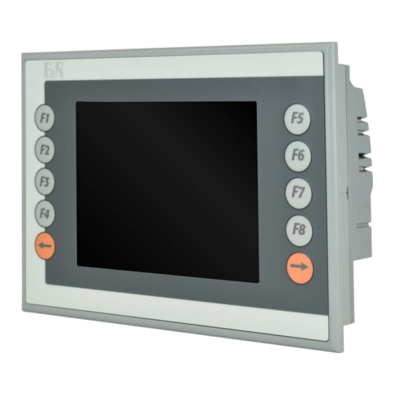
Page 3: Views
Views 1 Views Figure 1: 4PP065.0571-B00 - Oblique view Data sheetV 1.00 4PP065.0571-B00... - Page 4 Views Figure 2: 4PP065.0571-B00 - Rear view Data sheetV 1.00 4PP065.0571-B00...
-
Page 5: General Information
Table 1: 4PP065.0571-B00 - Order data 2.1.1 Description The 4PP065.0571-B00 is a variant of the standard device 4PP065.0571-X74F, with the following modifications: • Panel overlay design and slide-in labels same as standard PP45 (but PP45/PP65 imprint) • No embossing around display •... -
Page 6: Fully Assembled Device - Technical Data
LED operable by the user (with the AsHW library) Orange Module sending data via the X2X Link interface Orange CompactFlash card being accessed Table 4: 4PP065.0571-X74F - Diagnostic LEDs up to AR I2.96, D3.01 and A3.06 Data sheetV 1.00 4PP065.0571-B00... -
Page 7: Diagnostic Leds Starting With Ar J2.96, E3.01 And B3.06
Color Status Description Orange No Ethernet activity on the bus Blinking Ethernet activity on the bus Green A link to the remote station has been established. Table 7: 4PP065.0571-X74F - ACT/LNK LEDs for the RJ45 port Data sheetV 1.00 4PP065.0571-B00... -
Page 8: Connection Elements
X2X data inverted SHLD Shield Required accessories 0TB704.9 Terminal block accessory, 4-pin, screw clamp, 1.5 mm² 0TB704.91 Terminal block accessory, 4-pin, cage clamp, 2.5 mm² 4-pin male multipoint connector Table 8: 4PP065.0571-X74F - X2X Link pinout Data sheetV 1.00 4PP065.0571-B00... -
Page 9: Usb Ports
B&R cannot guarantee their performance. B&R does ensure the performance of all USB devices that they provide. Caution! Because this interface is designed according to general PC specifications, extreme care should be exercised with regard to EMC, cable routing, etc. Data sheetV 1.00 4PP065.0571-B00... -
Page 10: Ethernet Interface
Table 11: 4PP065.0571-X74F - Supply voltage pinout Caution! The functional ground must be connected to ground (e.g. control cabinet) using the shortest possible path. Using the largest possible conductor cross section on the supply plug is recommended. Data sheetV 1.00 4PP065.0571-B00... -
Page 11: Operating Mode And Node Number Switches
The CPU boots in Diagnostics mode. Does not initialize program sections in User RAM and User FlashPROM. After being in diagnostics mode, the CPU always boots with a cold restart. Table 12: 4PP065.0571-X74F - Operating mode and node number switches Data sheetV 1.00 4PP065.0571-B00... -
Page 12: Technical Data
Controller Intel 82551ER Design Shielded RJ45 port (10/100 Base-T) Transfer rate 10/100 Mbit/s Max. baud rate 100 Mbit/s Cables S/STP (Category 5) Status LEDs Link/Activity Design 4-pin male multipoint connector Table 13: 4PP065.0571-B00 - Technical data Data sheetV 1.00 4PP065.0571-B00... - Page 13 Pantone 427 C Dark gray border around display Pantone 432 C Color legend strips Pantone 428 C and Pantone 151 C Front Multi-layered overlay with insertion slots for key labels Table 13: 4PP065.0571-B00 - Technical data Data sheetV 1.00 4PP065.0571-B00...
- Page 14 Weight 0.75 kg Table 13: 4PP065.0571-B00 - Technical data Typical service life (at 50% buffer operation, 25°C when device off, 50°C when device on). Maximum service life in 24h operation (no buffer): 6 years at 25°C, 5 years at 50°C.
-
Page 15: Dimensions
Fully assembled device - Technical data 3.4 Dimensions Figure 7: 4PP065.0571-B00 - Dimensions Data sheetV 1.00 4PP065.0571-B00... -
Page 16: Cutout Installation
(various designs possible). Outer contour (Power Panel) Cutout dimensions 188 ±0.5 mm x 130 ±0.5 mm Cutout Figure 8: 4PP065.0571-B00 - Cutout installation Data sheetV 1.00 4PP065.0571-B00... -
Page 17: Panel Overlay Design
= Pantone 151 C = Transparent / unprinted = Cutout IMPORTANT: This image is not a true representation of the colors used on the panel overlay. The actual colors may vary slightly. Figure 9: 4PP065.0571-B00 - Panel overlay design Data sheetV 1.00 4PP065.0571-B00... -
Page 18: Slide-In Labels
= Pantone 151 C = Transparent / unprinted = Cutout IMPORTANT: This image is not a true representation of the colors used on the panel overlay. The actual colors may vary slightly. Figure 10: 4PP065.0571-B00 - Slide-in labels Data sheetV 1.00 4PP065.0571-B00... -
Page 19: Commissioning
Power Panel. The minimum specified spacing is indicated in the following diagrams. This applies to all Power Panel variants. Rear view At least At least 40 mm spacing 40 mm spacing Table 14: Spacing for air circulation - Rear view Data sheetV 1.00 4PP065.0571-B00... - Page 20 Commissioning Side view Air outlet At least 80 mm spacing Air inlet Table 15: Spacing for air circulation - Side view Data sheetV 1.00 4PP065.0571-B00...
-
Page 21: Mounting Orientation
The following diagram shows the approved mounting orientations for Power Panel devices. These mounting ori- entations apply to all Power Panel variants. Figure 11: Power Panel - Mounting orientations Caution! The maximum permitted ambient temperature can be found in the technical data for the respective Power Panel device. Data sheetV 1.00 4PP065.0571-B00... -
Page 22: Installing Interface Modules
It is possible to rotate screen contents by 90° using the graphic driver's screen rotation function. Automation Run- time supports this function. In Automation Studio 2.7.x or 3.0.x, the screen orientation can be defined when a project is created as well as later when editing the project. Data sheetV 1.00 4PP065.0571-B00... -
Page 23: Maintenance
500 hours Table 17: Battery status From the point when battery capacity is recognized as insufficient, data buffering is intact for approximately another 500 hours Information: The battery should only be changed by qualified personnel. Data sheetV 1.00 4PP065.0571-B00... -
Page 24: Procedure For Changing The Battery
Figure 13: Changing the battery - Removing the battery • In order to prevent a short circuit, do not touch the new battery with pliers or uninsulated tweezers. The battery should not be held by its edges. Incorrect Correct Figure 14: Battery handling Data sheetV 1.00 4PP065.0571-B00... -
Page 25: Changing The Compactflash Card
Rotate the orange CompactFlash safety latch away from the CompactFlash slot (1). Then press the CompactFlash ejection lever with a screwdriver (2) until the CompactFlash card is ejected. The CompactFlash card can now be removed by hand (3). Data sheetV 1.00 4PP065.0571-B00... -
Page 26: Inserting The Compactflash Card
If inserted incorrectly, the CompactFlash card will not go in all the way and the ejection lever will not extend out. Finally, rotate the safety latch over the CompactFlash slot (3) to secure the CompactFlash card (4). Data sheetV 1.00 4PP065.0571-B00... -
Page 27: Preventing Screen Burn-In On Lcd/Tft Displays
• Avoid static images or screen content. • Use non-static screensavers when the display is not in use. • Change images frequently. • Turn off the display when not in use. Turning off the backlight does not help prevent screen burn-in. Data sheetV 1.00 4PP065.0571-B00... - Page 28 4PP065.0571-X74F - Operating mode and node number switches........11 Figure 7: 4PP065.0571-B00 - Dimensions................... 15 Figure 8: 4PP065.0571-B00 - Cutout installation................. 16 Figure 9: 4PP065.0571-B00 - Panel overlay design................17 Figure 10: 4PP065.0571-B00 - Slide-in labels..................18 Figure 11: Power Panel - Mounting orientations..................21 Figure 12: Changing the battery - Removing the battery cover.............
- Page 29 Table index Table 1: 4PP065.0571-B00 - Order data....................5 Table 2: Version information........................5 Table 3: 4PP065.0571-X74F – Supported interface modules..............5 Table 4: 4PP065.0571-X74F - Diagnostic LEDs up to AR I2.96, D3.01 and A3.06........6 Table 5: 4PP065.0571-X74F - Diagnostic LEDs starting with AR J2.96, E3.01 and B3.06......7 Table 6: 4PP065.0571-X74F - Status LED blink code................
Need help?
Do you have a question about the 4PP065.0571-B00 and is the answer not in the manual?
Questions and answers