Kapro Prolaser 3D All-Lines User Manual
Hide thumbs
Also See for Prolaser 3D All-Lines:
- User manual (124 pages) ,
- User manual (124 pages) ,
- User manual (100 pages)

Related Manuals for Kapro Prolaser 3D All-Lines


Summary of Contents for Kapro Prolaser 3D All-Lines
- Page 1 Prolaser 3D All-Lines ® Model No. 883 User Manual Li-ion 4 AA 165'/50m Up to 60m/200' RECHARGEABLE INCLUDED...
- Page 2 Thank you for purchasing Kapro’s 883 Prolaser 3D All- Lines. ® You now own one of the most advanced laser tools available. This manual will show you how to get the most out of your laser tool. APPLICATIONS The 883 Prolaser 3D All- Lines is a laser level with 3 red diodes, ®...
-
Page 3: Table Of Contents
CONTENTS • Features • Safety instructions • Battery installation & Safety • Overview • Operating instructions 10-12 • Maintenance • Field calibration test 14-23 • Specifications • Warranty... -
Page 4: Features
FEATURES • This laser tool automatically determines the horizontal and vertical plans. • This laser emits 1 horizontal 360° and 2 orthogonal 360° vertical red beams, that intersect on 4 walls, floor and ceiling. • Self-leveling in automatic mode when the laser is positioned within its self-leveling range which is ±2.5º... -
Page 5: Safety Instructions
SAFETY INSTRUCTIONS WARNING This product emits radiation classified as Class II according to EN 60825 -1 The laser radiation can cause serious eye injury • Do not stare into the laser beam • Do not position the laser beam so that it unintentionally blinds you or others. - Page 6 • Do not remove or deface warning labels on the laser level. • Do not disassemble the laser level, laser radiation can cause serious eye injury. • Do not drop the unit. • Do not use solvents to clean the laser unit. •...
-
Page 7: Battery Installation & Safety
BATTERY INSTALLATION & SAFETY The 883 Prolaser 3D All- Lines offers 2 power supply options: ® a rechargeable Li-Ion battery pack or 4 AA Alkaline batteries (battery compartment included). Installation 1. Press down the latch of the battery cover. 2. Insert the Li-Ion battery pack or the battery compartment with the 4 AA Alkaline batteries, with the terminal contacts forward, according to the shape of the battery compartment. - Page 8 Charge the Li- Ion battery or use new AA Alkaline batteries if the beam/ battery indicator (b) starts to flash instead of emitting a steady light. NOTE: Connecting the charger with the charging adaptor to the power without the battery will show a steady green LED indicator with a small blinking dot.
-
Page 9: Overview
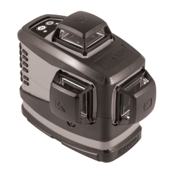
OVERVIEW 1. On/Off Locking Switch 2. Keypad Beam Selector/Manual mode button Beam / Battery indicator Pulse Mode button Pulse Mode indicator 3. Horizontal laser beam window 4. Forward vertical laser beam window 5. Side vertical laser beam window 6. Battery cover 7. -
Page 10: Operating Instructions
OPERATING INSTRUCTIONS Working in Automatic mode (self-leveling): In automatic mode the laser level will level itself in a ± 2.5° range and will project 1 horizontal 360° or/and 2 vertical 360° red beams. 1. Remove the laser level from the case and place it on a solid, flat, vibration free surface or on a tripod. - Page 11 Working in Manual mode: In Manual mode the 883 self-leveling mechanism is disabled and the laser beams can be set at any slope required. 1. Verify that the locking switch #1 is on the OFF position. 2. Press and hold the Manual mode button (a) for 3 seconds, to activate the manual mode.
- Page 12 Working in Pulse mode with a detector: For outdoor work under direct sunlight or bright conditions, and for extended indoor ranges up to 60 meters, use the pulse mode with a Detector. When the pulse mode is activated the laser beams will flash at a very high frequency (invisible to the human eye).
-
Page 13: Maintenance
MAINTENANCE To maintain the accuracy of your project, check the accuracy of your laser level according to the field calibration tests procedures. • Change the battery when the laser beams begins to dim. • Wipe the aperture lens and the body of the laser level with a clean soft cloth. -
Page 14: Field Calibration Test
FIELD CALIBRATION TEST This laser level left the factory fully calibrated. Kapro recommends the user check the accuracy of the laser periodically, especially if the unit falls or is mishandled. 1. Check the height accuracy of the cross created by the lateral (#5) and the horizontal lines. - Page 15 approximately 5m Figure # 1 0.5m 6) Turn the laser 180° towards wall B. Reposition the laser and verify that the 2 vertical lines pass through a1 and c1. 7) Mark on wall B the center of the cross beams as b1 (see figure # 2).
- Page 16 8) Without turning the laser level, lock the pendulum and move the laser level towards wall B and position it approximately 0.5 meter from wall B. 9) Unlock the pendulum and press the Beam Selector (a) twice to project all 3 lasers beams. 10) Verify that the vertical line passes through a1and b1.
- Page 17 180° Figure # 4 0.5m 14) Measure the distances: Δa= |a2-a1| Δb= |b1-b2| 15) The difference | Δa – Δb| should be no more than 3 mm, otherwise send the laser level to a qualified technician for repair.
- Page 18 2. Checking the Height Accuracy of the cross created by the longitudinal (#4) and Horizontal lines. (Up and down deviation) 1) Set up the laser on a table or on the floor between 3 walls A, B and C. The distance between A and B should be approximately 5 meters.
- Page 19 Figure # 5 3) Set up the laser on a tripod or on a solid surface in front of the wall, at a distance of approximately 2 meters. 4) Unlock the pendulum and press the button to project the vertical forward beam (#4) towards the plumb line. 5) Turn the laser, so the vertical beam will merge with the plumb line below the hanging point.
- Page 20 Figure #6 7) The distance between a1 and a2, should be no more than 1mm, otherwise send the laser level to a qualified technician for repair. 4. Checking the Accuracy of the side Vertical beam (#5). For the second vertical beam, repeat the previous marking procedures from paragraph 1 -7.
- Page 21 5. Checking 90º accuracy between the 2 Vertical beams. This procedure requires a room of at least 5x5 meters with 3 walls. 1) Set up the laser on a table or on the floor in the middle of the room. 2) Unlock the pendulum and press the button Beam Selector (a) twice, to project the forward and the side vertical beams 3) Mark the center of the side vertical beam in 3 places;...
- Page 22 2.5m 2.5m Figure # 7 5) Rotate the laser 90° counterclockwise so that the cross beams pass through c1 on the table, and the forward laser beam passes through the marks a1 and b1 on the walls A and B respectively. 6) Mark as c3 the center of the side vertical beam on wall C, at the same height as point c2.
- Page 23 2.5m 2.5m Figure # 8 7) The distance between c2 and c3, should be no more than 1.5mm, otherwise send the laser level to a qualified technician for repair.
-
Page 24: Specifications
SPECIFICATIONS Laser beams • Horizontal 360° output pattern • Side vertical 360° • Both verticals 360° • Horizontal and verticals all 360° Laser range • Indoor - 20m (65ft) with red goggles • With detector - 60m (200ft) Accuracy ±0.2mm/m (±0.0002in/in) Self-leveling Range ±2.5°... -
Page 25: Warranty
The warranty does not cover products that are used improperly, altered or repaired without Kapro Tool's approval. In the event of a problem with the laser level, please return the product to the place of purchase with proof of purchase. - Page 28 Rev. 1.0 © 2019 Kapro Industries Ltd.
Need help?
Do you have a question about the Prolaser 3D All-Lines and is the answer not in the manual?
Questions and answers