Table of Contents
Advertisement
Advertisement
Table of Contents

Related Manuals for Mac Medical D Series


Summary of Contents for Mac Medical D Series
- Page 1 INSTRUCTION MANUAL D-Series Warming Cabinets Installation - Operation - Maintenance OSHPD Pre-Approved Read and understand all of the instructions and safety information in this manual before operating this product. 10/2018 MAN-001 Rev J © 2018 MAC Medical, Inc.
-
Page 2: Table Of Contents
Instruction Manual TAble Of COnTenTS Summary D-Series Warming Cabinet Models Interior Dimensions, Cubic Foot Capacity, Approximate Capacity General Specifications Main Features of a Typical Warming Cabinet Warnings and Cautions Unpacking Instructions Receiving Requirements Installing D-Series Warming Cabinets Environmental Conditions Installation Testing before Using Installing Warming Cabinet Leg Levelers Optional Direct Wiring Using Facility Power Supply... -
Page 3: Summary
Indications for Use: The MAC Medical Inc. Blanket and Solution Warming Cabinets are designed to store and warm blankets, hospital linens, irrigation fluids, and/or injection fluids in accordance with recommended warming temperatures and storage time guidelines provided by the manufacturers of such products. -
Page 4: D-Series Warming Cabinet Models
Instruction Manual D-Series Warming Cabinet Models Model # Overall Size Chambers Door Type Door Hinge base Style Other Options SWC151822 17.25"D x 18"W x 22"H Single G=Glass Door LH=Left Hinge 2B = 2” Base 220 = 220/240V Power Supply SWC182424 20.5"D x 24"W x 24.5"H Single Blank = Right... -
Page 5: Interior Dimensions, Cubic Foot Capacity, Approximate Capacity
Instruction Manual Interior Dimensions, Cubic foot Capacity, Approximate Capacity Model # Upper or single Middle lower Cubic foot Cubic foot Cubic foot Approximate Chamber Chamber Chamber Capacity Capacity Capacity Capacity (h x w x d) in (h x w x d) (h x w x d) Upper or single Middle... - Page 6 Instruction Manual Usable Chamber Space The usable chamber space of the single, dual and triple cabinets is slightly different from the height, width, and depth interior dimensions in the table on the previous page. Note that the usable chamber inner height is measured from the bottom of the air box to the USABLE INNER HEIGHT...
-
Page 7: General Specifications
Instruction Manual General Specifications Cabinet Construction and Material • 300 Stainless Steel (all panels, header and doors) Double walled construction with insulation. Doors are double pan stainless steel. • Fully insulated to provide uniform heating • Optional Glass door are double paned tempered glass framed with aluminum. •... - Page 8 Instruction Manual MAC Medical Warming Cabinet handles are equipped with CuVerro® bactericidal copper surfaces. ° This product is made from a copper surface that continuously kills bacteria* left behind by dirty hands, killing more than 99.9% of bacteria* within 2 hours.
-
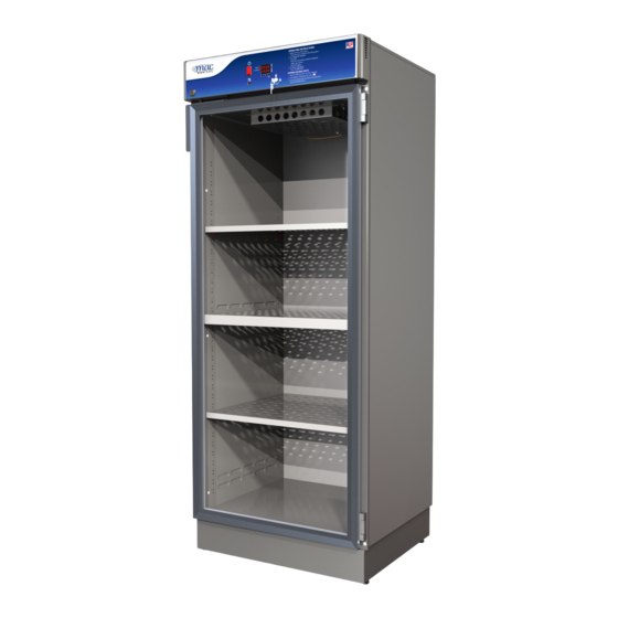
Page 9: Main Features Of A Typical Warming Cabinet
Instruction Manual Main features of a Typical Warming Cabinet (Single Chamber Cabinet shown here) Fig. 5: Main Elements of a Warming Cabinet This list shows the main elements of a warming cabinet. For a list of replacement parts with their part numbers and quantities, see”Replacement Parts - General”... -
Page 10: Warnings And Cautions
Instruction Manual Warnings and Cautions The following is a list identifying the various warning and caution icon used in this manual. Icon Type Icon Description Warnings (Red triangle with an exclamation point) indicates the potential for minor to severe injuries up to and including death to personnel. Cautions (Yellow triangle with an exclamation point) indicates the potential minor injury to personnel and damage to equipment. - Page 11 MAC Medical, Inc. or by other manufacturers, unless such a combination has been specifically endorsed, in writing, by MAC Medical, Inc.
-
Page 12: Unpacking Instructions
Instruction Manual Unpacking Instructions plastic protective wrapping around the Warming Cabinet. These items can scratch the protective coating on the stainless steel Receiving Requirements allowing the surface to rust. The customer is responsible for making sure the 9. The Warming Cabinet is now ready for use. loading dock at their facility can accommodate a 10. -
Page 13: Installing D-Series Warming Cabinets
1. Carefully uncrate the D-Series Warming Cabinet. environmental Conditions 2. Inspect for any damage. If there is damage, please contact MAC Medical, Inc. at (1-877-828- This unit is intended for use in a stable ambient environment, with an ideal temperature of 72° F 9975). -
Page 14: Installing Warming Cabinet Leg Levelers
Instruction Manual Installing Warming Cabinet leg levelers Working with at least two people, carefully tilt the Warming Cabinet back slightly and insert the 4 Leg Warming Cabinets are shipped with 4 Leg Levelers Levelers up into the 4 provided holes (Fig. 9). which must installed by the customer (Fig. -
Page 15: Optional Direct Wiring Using Facility Power Supply
Instruction Manual Optional Direct Wiring Using facility Power Supply NOTE: The following procedure must be performed by a qualified electrical technician to avoid personal injury or damage to the unit. Warming Cabinets can be wired directly into the facility’s wiring by following these steps: 1. -
Page 16: Basic Operation
For more information, please contact MAC Medical, Inc. In Case of Power failure For blankets, follow blanket manufacturer’s instructions for the set point. -
Page 17: Explanation Of The Controls
Instruction Manual explanation of the Controls Fig. 15: Controller Display The Controls are located on the upper panel (Fig. 10) on the front of the cabinet. For multi-chamber cabinets, there are sets of controls for each individual chamber. Each control set is clearly labeled UPPER CHAMBER and LOWER CHAMBER for dual chamber cabinets and UPPER CHAMBER, MIDDLE CHAMBER and LOWER CHAMBER for the triple chamber cabinets. -
Page 18: Operation Of Display Panel
▼ arrow key (to lower the setpoint). operating conditions, turn power to specific chamber The setpoint is indicated in the lower row of the off and call your Mac Medical representative at display. 1-877-828-9975. 3. Press “SET” again to complete the change (If dual or triple chamber unit, steps must be completed for all chambers). -
Page 19: Installing The Shelves
Instruction Manual Installing the Shelves Adjusting the Shelves 1. Where applicable, turn the power OFF to the 1. Turn the power OFF to the heating chamber that heating chamber that needs a shelf installed in it. needs its shelf adjusted. A. -
Page 20: Installing And Adjusting Optional Roller Basket Shelves
Instruction Manual Installing and Adjusting Optional Roller basket Shelves Install the roller basket shelf by first attaching the two roller channels to the cabinet walls. 1. First, insert the top tab of one end of the roller channel into a slot (the roller channel width spans 4 slots). Fig. 15 &... -
Page 21: Unloading The Warming Cabinet
Fig. 21. 1. Insert the MAC Medical flash drive (W0600-S) or equivalent into the USB port marked DATA (located on the front face of the control panel). -
Page 22: Troubleshooting
Reload the contents using the proper loading guidelines as previously mentioned in this manual. Turn on the chamber and monitor performance. If the chamber continues to overheat into an alarm (HI) condition, turn off the chamber and contact your MAC Medical authorized service personnel. MAN-001 www.macmedical.com... -
Page 23: Cleaning Stainless Steel Warming Cabinets
Instruction Manual Cleaning Stainless Steel Warming Cabinets Stainless steel Warming Cabinets must be cleaned on a regular basis to prevent any unnecessary damage to the stainless steel surfaces. Spilled liquids and standing water should be cleaned up immediately. When cleaning stainless steel Warming Cabinets, make sure to use the proper approved cleaning agents and cleaning materials to protect the surface and prevent damage or corrosion. -
Page 24: Preventative Maintenance Checklist
Inspect the Fan blades for buildup of lint and other shelves sit upon. Make sure these are not loose. If any debris. Clean as necessary. nOTe: MAC Medical are loose, snap back into place. recommends replacing the Fan Motor with Fan blade... -
Page 25: Replacement Parts - General
Instruction Manual Replacement Parts - General D-Series Warming Cabinet replacement parts listed on this page have been identified by MAC Medical as serviceable by facility personnel and are available for purchase. To obtain MAC Medical certified parts and authorized services, contact your MAC Medical representative. -
Page 26: Replacement Parts - Header Assembly And Electrical Drawer
For Fig. 27: Replacement parts in header assembly optimal usage, safety and durability of the product, service must be performed by a MAC Medical authorized service technicians using MAC Medical authorized replacement parts and service techniques. - Page 27 Instruction Manual Table 1 Item # Part # Header Assembly and electrical Item # Part # Header Assembly and electrical Drawer Parts Description Drawer Parts Description W0011 Power Switch See table 2 Heating Element W0083 Solid State Relay W0010 Ceramics W0137 Heat Sink Pad W0037...
-
Page 28: Optional Cabinet Bases, Mobile Bases And Mobile Stands
Instruction Manual Optional Cabinet bases, Mobile bases Part # base and Mobile Stands SMW0307-02 4” base for 18 x 24 cabinets All warming cabinets are shipped with SMW0359-02-WM 2” base for 18 x 24 cabinets a standard 4” base unless otherwise SMW0359-03-WM 6”... -
Page 29: Steel Or Glass Door Hinge Reversal
Instruction Manual Steel or Glass Door Hinge Reversal Before the Door Hinges can be reversed, the top and side panels of the cabinet must be removed, and the Cam Lock must be relocated. Remove Panels The Following steps for panel removal apply to cabinets with either steel or glass doors. -
Page 30: Remove Header Assembly Box & Relocate Cam Lock
Instruction Manual Remove Header Assembly box & Relocate Cam lock Purchase Parts needed for Cam lock Reversal • Felt Strip ST0014 • Plug W0098 The following steps apply to cabinets with steel or glass doors. Cabinets are equipped with a cam lock in the header assembly. - Page 31 Instruction Manual 6. At the new cam lock location, remove the 2 oblong knock-out areas. Cut an oblong shape in the plastic overlay covering the short-wide oblong knock-out area to accomodate the cam lock when it is re-installed (Fig. 37 and Fig. 38). The narrow-long oblong knock-out area will be the slot the cam lock latch fits in. Fig.
- Page 32 Instruction Manual 12. Secure the Cam Lock body to the header by attaching the Lock Washer, then the Hex Nut. 13. Affix the Cam Lock Latch to the Cam Lock body and secure it with a 8-32 Phillips head screw. 14.
-
Page 33: Glass Door Hinge Reversal And Re-Installation
Instruction Manual Glass Door Hinge Reversal and Re-installation Following are instructions for the removal, hinge reversal, and re-installation of Glass Doors. note: No additional parts are required to perform Glass Door hinge reversal. However, it may be nec- essary to drill holes in the bottom of the Glass Door to enable relocation of the Cam Lock Plate to its new position. - Page 34 Instruction Manual 3. Unscrew the Door Handle and Cam Lock Plate from their present position and move them to the other side of the door. Make sure to “mirror” the Cam Lock Plate so that its top flange will be flush against the warming cabinet when the door is re-installed in its new position (Fig.
- Page 35 Instruction Manual 5. Once the holes are drilled for the Cam Lock Plate, move both the Cam Lock Plate and the Door Handle to their new positions (Figure 50). When installed, there should be at least a 1/4” gap between the Cam Lock Plate and the face of the Cabinet (Figure 51).
- Page 36 Instruction Manual 7. Use a flathead screwdriver to remove the 2 smaller satin plugs (circled in red) from the top and bottom of the opposite side of the cabinet. These are the new hinge positions (Fig. 54). 8. Re-insert the 2 satin plugs (that were removed from the new hinge positions) in the old hinge positions. Fig.
- Page 37 Instruction Manual 11. To secure the door to its hinges, drive the hinge pins through the two halves of the hinges. Both pins should be driven into the hinges from the inside to the outside as shown in Fig. 57. 12.
-
Page 38: Steel Door Hinge Reversal And Re-Installation
Instruction Manual Steel Door Hinge Reversal and Re-installation Purchase Parts needed for Door Hinge Reversal • Intermediate Hinge (for multiple door units only) W0015 (Right Hand) or W0016 (Left Hand). Obtain the intermediate hinge opposite of the currently installed hinge. 1. - Page 39 Instruction Manual 3. After the door is removed, unscrew the Door Handle and Cam Lock Plate from their present position and move them to the bottom of the door. Be sure to “mirror” the Cam Lock Plate so that its top flange will be flush against the warming cabinet when the door is re-installed in its new position (Fig.
- Page 40 Instruction Manual 8. Look at the socket located on both the top and bottom of the door (circled in red in Fig. 66). The pins of the door hinges will insert into these. Fit the bottom socket of the door onto the bottom hinge pin. Support the door on its bottom hinge while you prepare to affix the door to the top hinge.
-
Page 41: Wiring Diagram - Single Chamber Warmers
Instruction Manual Wiring Diagram - Single Chamber Warmers MAN-001 www.macmedical.com... -
Page 42: Wiring Diagram - Dual Chamber Warmers
Instruction Manual Wiring Diagram - Dual Chamber Warmers MAN-001 www.macmedical.com... -
Page 43: Wiring Diagram - Triple Chamber Warmers
Instruction Manual Wiring Diagram - Triple Chamber Warmers MAN-001 www.macmedical.com... -
Page 44: Index
Instruction Manual Index Header Assembly and Electrical Drawer 24 Shelves Cabinet bases, Mobile bases and Mobile Stands 26 Adjusting 17 Cleaning 21 Installation 17 Approved cleaning materials and agents 21 Roller Basket Decals or Printed Labels 21 Adjusting 18 Disinfecting Stainless Steel 21 Installation 18 Glass Doors 21 Part Numbers 26... - Page 45 Instruction Manual Preventative Maintenance Record for your convenience, here is a simple chart to use to note which personnel have been trained to safely use and maintain the warming cabinet. Personnel Trained Daily Operation Safety Instruction Cleaning Procedures This chart refers to the procedures on the “Preventative Maintenance Checklist” on page 56. Date of Weekly Inspection Date of Monthly Inspection Date of Semi-Annual Testing...
- Page 46 Instruction Manual notes __________________________________________________________________________________________ __________________________________________________________________________________________ __________________________________________________________________________________________ _________________________________________________________________________________________ _________________________________________________________________________________________ __________________________________________________________________________________________ __________________________________________________________________________________________ __________________________________________________________________________________________ __________________________________________________________________________________________ __________________________________________________________________________________________ __________________________________________________________________________________________ __________________________________________________________________________________________ __________________________________________________________________________________________ __________________________________________________________________________________________ __________________________________________________________________________________________ __________________________________________________________________________________________ __________________________________________________________________________________________ __________________________________________________________________________________________ __________________________________________________________________________________________ __________________________________________________________________________________________ __________________________________________________________________________________________ __________________________________________________________________________________________ __________________________________________________________________________________________ __________________________________________________________________________________________ __________________________________________________________________________________________ __________________________________________________________________________________________ __________________________________________________________________________________________ __________________________________________________________________________________________ __________________________________________________________________________________________ __________________________________________________________________________________________ __________________________________________________________________________________________ __________________________________________________________________________________________ __________________________________________________________________________________________ __________________________________________________________________________________________ __________________________________________________________________________________________ _________________________________________________________________________________________ _________________________________________________________________________________________ __________________________________________________________________________________________ __________________________________________________________________________________________ __________________________________________________________________________________________...
- Page 47 Instruction Manual notes __________________________________________________________________________________________ __________________________________________________________________________________________ __________________________________________________________________________________________ _________________________________________________________________________________________ _________________________________________________________________________________________ __________________________________________________________________________________________ __________________________________________________________________________________________ __________________________________________________________________________________________ __________________________________________________________________________________________ __________________________________________________________________________________________ __________________________________________________________________________________________ __________________________________________________________________________________________ __________________________________________________________________________________________ __________________________________________________________________________________________ __________________________________________________________________________________________ __________________________________________________________________________________________ __________________________________________________________________________________________ __________________________________________________________________________________________ __________________________________________________________________________________________ __________________________________________________________________________________________ __________________________________________________________________________________________ __________________________________________________________________________________________ __________________________________________________________________________________________ __________________________________________________________________________________________ __________________________________________________________________________________________ __________________________________________________________________________________________ __________________________________________________________________________________________ __________________________________________________________________________________________ __________________________________________________________________________________________ __________________________________________________________________________________________ __________________________________________________________________________________________ __________________________________________________________________________________________ __________________________________________________________________________________________ __________________________________________________________________________________________ __________________________________________________________________________________________ _________________________________________________________________________________________ _________________________________________________________________________________________ __________________________________________________________________________________________ __________________________________________________________________________________________ __________________________________________________________________________________________...
-
Page 48: Limited Lifetime Warranty
EXPRESS OR IMPLIED, OF FITNESS AND / OR MERCHANTABILITY OR ANY OTHER WARRANTY IMPLIED BY CUSTOM, USAGE OR COURSE OF DEALING. Liability of MAC Medical under this warranty is limited to the repair and / or replacement of any products. MAC Medical specifically excludes and disclaims any responsibility for any incidental or consequential damages claimed to have arisen from any defect in workmanship or materials.
Need help?
Do you have a question about the D Series and is the answer not in the manual?
Questions and answers