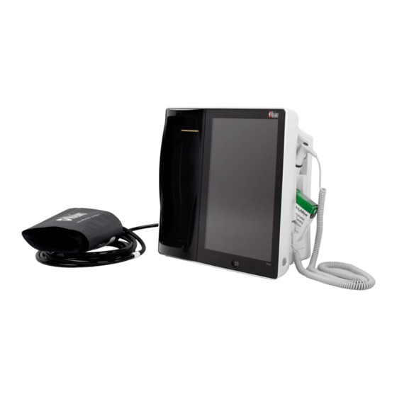
Masimo Root Operator's Manual
With noninvasive blood pressure and temperature
Hide thumbs
Also See for Root:
- Operator's manual (116 pages) ,
- Operator's manual (172 pages) ,
- Manual (36 pages)
Table of Contents
Advertisement
Quick Links
Advertisement
Table of Contents

Related Manuals for Masimo Root


Summary of Contents for Masimo Root
- Page 1 Operator's Manual ® Root with noninvasive blood pressure and temperature...
- Page 3 These operating instructions provide the necessary information for proper operation of all models of the Root. There may be information provided in this manual that is not relevant for your system. General knowledge of pulse oximetry and an understanding of the features and functions of Root are prerequisites for its proper use.
-
Page 5: Table Of Contents
Chapter 3: Operation -------------------------------------------------------------------------------------- 29 About the Status Bar ---------------------------------------------------------------------------------- 29 About the Main Screen -------------------------------------------------------------------------------- 31 Using the Touchscreen Interface -------------------------------------------------------------------- 32 Menu Navigation -------------------------------------------------------------------------------------- 35 Understanding Windows ----------------------------------------------------------------------------- 36 Accessing Main Menu Options ----------------------------------------------------------------------- 42 Alarm Interface ---------------------------------------------------------------------------------------- 68 www.masimo.com Masimo... - Page 6 Using Iris Connectivity Ports ---------------------------------------------------------------------- 109 Chapter 10: Messages ----------------------------------------------------------------------------------- 111 Chapter 11: Troubleshooting --------------------------------------------------------------------------- 115 Troubleshooting Radical-7, Radius-7, and MOC-9 Modules ------------------------------------ 115 Troubleshooting Root -------------------------------------------------------------------------------- 115 Chapter 12: Specifications ------------------------------------------------------------------------------ 117 Measurement Accuracy ------------------------------------------------------------------------------ 117 Display Ranges ---------------------------------------------------------------------------------------- 118...
- Page 7 Nurse Call Setting Connections ------------------------------------------------------------------- 139 Battery Test ------------------------------------------------------------------------------------------- 139 Repair Policy ------------------------------------------------------------------------------------------ 140 Return Procedure ------------------------------------------------------------------------------------- 140 Contacting Masimo ---------------------------------------------------------------------------------- 140 Limited Warranty ------------------------------------------------------------------------------------- 141 Exclusions ---------------------------------------------------------------------------------------------- 141 Limitation of Warranty ------------------------------------------------------------------------------ 142 Sales & End-User License Agreement ------------------------------------------------------------ 142...
-
Page 9: About This Manual
About this Manual This manual explains how to set up and use Root®. Important safety information relating to general use of Root appears in this manual. Read and follow any warnings, cautions, and notes presented throughout this manual. The following are explanations of warnings, cautions, and notes. -
Page 11: Product Description, Features, And Indications For Use
The Masimo Root Monitoring System is indicated for use by healthcare professionals for the monitoring of multiple physiological parameters in healthcare environments. The Masimo Root Monitoring System, when used with the optional ISA module, is not intended to be used in road ambulances. -
Page 12: Contraindication
Root Product Description, Features, and Indications for Use (SpO2), pulse rate, and/or respiratory rate (RRa). The Masimo Radius-7 Wearable Pulse Oximeter and accessories are indicated for use with adult, and pediatric patients during both no motion and motion conditions, and for patients who are well or poorly perfused in hospitals, and hospital-type facilities. -
Page 13: Safety Information, Warnings, And Cautions
Cautions Note: Pediatric population does not include neonates. Note: When the ISA module is used with Root, the combination of the ISA module and Root is not indicated for use outside the healthcare facility. CAUTION: Root is to be operated by, or under the supervision of, qualified personnel only. The manual, accessories, directions for use, all precautionary information, and specifications should be read before use. -
Page 14: Safety Warnings And Cautions
WARNING: Do not use Root during or nearby magnetic resonance imaging (MRI) or in an MRI environment. WARNING: Do not place Root or accessories in any position that might cause it to fall on the patient. WARNING: To ensure safety, avoid stacking multiple devices or placing anything on the device during operation. - Page 15 Note: Do not monitor more than a single patient at a time on Root. Note: It is recommended that Root is attached to an AC power source when it is not in use to ensure that the battery remains fully charged.
-
Page 16: Performance Warnings And Cautions
Safety Information, Warnings, and Cautions Performance Warnings and Cautions WARNING: Root should not be used as the sole basis for medical decisions. It must be used in conjunction with clinical signs and symptoms. WARNING: Root may be used during defibrillation, but this may affect the accuracy or availability of the parameters and measurements. - Page 17 CAUTION: Do not place the Root on electrical equipment that may affect the device, preventing it from working properly. CAUTION: Failure to charge Root promptly after a Low Battery alarm may result in the device shutting down. CAUTION: To minimize radio interference, other electrical equipment that emits radio frequency transmissions should not be in close proximity to Root.
-
Page 18: Cleaning And Service Warnings And Cautions
CAUTION: Do not submerge the Root in any cleaning solution or attempt to sterilize by autoclave, irradiation, steam, gas, ethylene oxide or any other method. This will seriously damage the device. - Page 19 These limits are designed to provide reasonable protection against harmful interference in a hospital environment. Note: This Class A digital apparatus complies with Canadian ICES-003. Note: Root is not intended for use during patient transport outside the healthcare facility. www.masimo.com Masimo...
-
Page 21: Chapter 1: Description
Chapter 1: Description Root can be used in the following ways: • As a docking station and charger for Radical-7 and Radius-7 Battery Module. • As a bedside monitoring display for parameters on Radical-7, Radius-7, and MOC-9 modules. • As a bedside monitor for continuous or non-continuous NIBP and temperature. -
Page 22: Features
Provides a frontal display and interface for user interactions. Touchscreen Home Button Provides access to the Main Screen. Root Charging Shows an indication of the battery charge for Root. Indicator AC Power Shows an indication of AC power connection Root. Indicator... - Page 23 Nurse Call Provides a connection to a Nurse Call system. Connector Ethernet Port Provides a network connection to Root using an RJ-45 cable. USB Ports (2) Provide USB 2.0 connectivity. Power Entry Contains the input connector for a hospital grade AC power cord Module and the fuse holder.
- Page 24 Provides an indication of system messages and alarm priority. System Status Lights See System Status Lights on page 75. Power Button Places Root in Power On, Sleep, and Power Off modes. MOC-9 Ports (3) Provide connectivity for MOC-9 modules. NIBP Nib Connection port for NIBP Hose.
-
Page 25: Chapter 2: Setting Up
If anything is missing or damaged, contact Masimo's Technical Service Department. See Return Procedure on page 140. Guidelines for Setting Up Root has a built-in bracket interface that allows it to be mounted on a pole or roll stand. When setting up Root, follow these guidelines: •... -
Page 26: Power On
Power Button for two (2) seconds until a single audible tone sounds. Once Root turns on, if no Radical-7, Radius-7, or MOC-9 module is connected, the Root display shows the following message: Please Connect a Device. The user is now able to connect Radical-7, Radius-7, and MOC-9 module. -
Page 27: Initial Battery Charging
2. Plug the hospital grade AC power cord into an AC power source. 3. Verify that Root's battery is charging by ensuring that the AC Power Indicator (1) is green and the Battery icon on the Status Bar (2) is solid green or has the charging symbol. -
Page 28: Radical-7 Connection
Root Chapter 2: Setting Up Radical-7 Connection It is recommended that Root be powered on before performing the steps below. • Snap the Radical-7 into the Docking Station. • If the Radical-7 is not yet turned on, press the power button on the Radical-7 to power it on. -
Page 29: Radius-7 Connection
Root Chapter 2: Setting Up Radius-7 Connection It is recommended that Root be powered on before performing the steps below. Ensure the Radius-7 Battery Charging Adapter is properly docked in the Docking Station area of Root. Activate the Bluetooth radio on Root. (for more information see Operator’s Manual for Radius-7). -
Page 30: Attach The Probe Well
Place probe cover onto the temperature probe and dock in the probe well. Attach NIBP Cuff Attach a necessary adapter to the end of the cuff hose. Connect blood pressure cuff to the NIBP Nib located on the side of Root. www.masimo.com Masimo... -
Page 31: Chapter 3: Operation
Chapter 3: Operation The information in this chapter assumes that Root is set up and ready for use. This chapter provides necessary information for proper operation of the device. Do not operate Root without completely reading and understanding these instructions. - Page 32 Battery See Radical-7 and Radius-7 Charging Indicator on page 77. Displays charging status for Root and provides access to the Battery Root screen. The example shows that the battery is currently charging. Root Battery See Root Charging Indicator on page 76.
-
Page 33: About The Main Screen
Provides a dynamic, user-configurable display area for all the data from Windows connected medical devices. Main Menu Provides access to the configuration options for Root and connected icon medical devices. See Accessing Main Menu Options on page 42. www.masimo.com Masimo... -
Page 34: Using The Touchscreen Interface
Root Chapter 3: Operation Using the Touchscreen Interface Using the gestures described below, the user is able to customize the viewing experience, including displaying the highest priority parameters and measurements. The availability of navigation features is dependent on the connected medical devices. - Page 35 Root Chapter 3: Operation Below is a list of all the different types of controls available on Root and the various ways to interact with each type of control. Control Applicable Actions Description Toggle Slide knob Switches between toggle states...
- Page 36 Root Chapter 3: Operation Control Applicable Actions Description Press anywhere When open, collapses spinner outside spinner Button Press Performs action (as defined by the button description) Icon Menu Press tile Opens menu specified by tile Swipe left or right Scrolls icons left or right...
-
Page 37: Menu Navigation
To navigate to the previous screen, press the arrow at the top left corner of the touchscreen. To return to the Main Screen, at any time, press the Home Button at any time. The Home Button is always illuminated when Root is powered on. www.masimo.com... -
Page 38: Understanding Windows
Chapter 3: Operation Understanding Windows Root creates a Window for Radical-7, Radius-7, and compatible medical devices that are connected to Root. Parameters or measurements can be expanded or minimized within a Window to customize view. Radical-7 Windows are shown in the examples below. - Page 39 Root Chapter 3: Operation (Available only in Analog View) Parameters and measurements are shown as Analog Gauges in Analog View. A parameter's Analog Gauge Analog includes its Alarm Limits, Numeric Value, Parameter Label, as well as Gauge Alarming, Caution and Normal Ranges. See Using Analog View on page...
- Page 40 Root Chapter 3: Operation Using Analog View The Analog View shows parameter and measurement data as a needle pointing to graduations in a circular array around a dial. This view provides indications of change that can be interpreted at a quick glance.
- Page 41 Root Chapter 3: Operation Specific ranges of the Analog View are: Ref. Feature Color Description White Area of the display range where an alarm will not be Normal Range triggered. Caution Range Yellow Area of the display range that provides a caution indicator.
- Page 42 Root Chapter 3: Operation Customizing Windows Windows can be customized by expanding and minimizing parameters and measurements in both Trend View and Analog View. When a parameter is minimized, it is only displayed in the Well with its Numeric Value and Parameter Label. When a parameter is expanded, it will be shown as either a Trend Display or Gauge.
- Page 43 Root Chapter 3: Operation Minimizing a parameter or measurement Order Instruction Step 1 Press and hold the Numeric Value until it shrinks. Step 2 Drag the Numeric Value to the Well. Step 3 Release the Numeric Value. www.masimo.com Masimo...
-
Page 44: Accessing Main Menu Options
Root Chapter 3: Operation Accessing Main Menu Options To access the Main Menu options At the bottom right corner of the touchscreen, press the Main Menu icon. The Main Menu options are: Device Settings See Device Settings on page 43. - Page 45 Root Chapter 3: Operation Device Settings The Device Settings menu allows the user to view and customize settings for Root. The Device Settings options are: Localization See Localization on page 44. Wi-Fi See Wi-Fi on page 45. Ethernet See Ethernet on page 46.
- Page 46 Option Description Factory Default Configurable Settings Setting Selects the language display Choose from available Language English for Root. languages. mm/dd/yy or Date Format Sets the display format for mm/dd/yy current date. dd/mm/yy 12 hour or Sets the display format for...
- Page 47 Wi-Fi communication feature in order to preserve Root’s primary alarms. Use the Wi-Fi screen to enable or disable Wi-Fi connectivity. When Root is connected to a Wi-Fi network, the Wi-Fi icon on the Status Bar conveys the strength of the connection. See About the Status Bar on page 29.
- Page 48 The Bluetooth radio allows for the detection of the close proximity of Masimo’s MyView Presence Tag. Root’s detection of Masimo’s MyView Presence Tag is an optional feature that allows for the display of predetermined customized settings by a clinician. Root utilizes only configured MAC addresses to establish Bluetooth communication to prevent unauthorized connection to other Bluetooth enabled devices.
- Page 49 Chapter 3: Operation Root Battery Use the Root Battery screen to view the specific percentage of charge on the battery. The user can also access Root's Battery screen by pressing the Battery icon on the Status Bar. See About the Status Bar on page 29.
- Page 50 Root Chapter 3: Operation Brightness Use the Brightness screen to adjust the brightness of the Root display. Option Description Factory Configurable Default Settings Setting Auto Allows automatic adjustment of Root's display brightness based on ambient light. Off On or Off...
- Page 51 Root Chapter 3: Operation Press Enter to access the password protected screen. Note: The password will have to be entered every time this screen is accessed. Option Description Factory Configurable Settings Default Setting Enable parameter Alarm Silence All Mute menu option. See Sounds on page...
- Page 52 Root Chapter 3: Operation Device Output A Nurse Call can be triggered based on alarm, low Signal IQ events or both. In addition, Nurse Call Polarity can be inverted to accommodate local Nurse Call station requirements. Option Description Factory Configurable Settings...
- Page 53 IntelliBridge connectivity allows Root to transmit parameters and waveforms to Philips multi-parameter patient monitors that support Philips IntelliBridge device interfacing modules. This option allows parameters and waveforms on Root to be displayed on a Philips monitor and, if applicable, transmitted to the electronic medical record system.
- Page 54 Chapter 3: Operation About Use the About screen to view the serial number as well as software and hardware version information about Root. These details may be helpful during troubleshooting. Option Description Serial Number Displays the serial number for the device.
- Page 55 Category type. Root can be configured for various patient types by using the Profiles feature. Profile selection controls the management of patient configuration settings on Root. The settings of the three default profiles (Adult, Pediatric, and Neonatal) configure parameter alarms, averaging time, and sensitivity modes.
- Page 56 Root Chapter 3: Operation Layout Use the Layout screen to select sizing options for Windows and Trend Displays. Additional Settings There are different ways to display the parameters and measurements by changing the Layout Style. Note: This feature only applies to Trend View. See Using Trend View on page 37.
- Page 57 Trend Displays. Available Layout When only Radical-7, Radius-7, or a single MOC-9 module is connected to Root, the Available Layout will be 100%. When Radical-7 and/or multiple devices are connected, the user will have the option to select from several pre-configured layouts.
- Page 58 Root Chapter 3: Operation Sounds Use the Sounds screen to control the volume level of sounds and duration of audio pause for Root. Option Description Factory Configurable Settings Default Setting Alarm Highest Slide towards the left to decrease Sets the alarm volume level.
- Page 59 Root Chapter 3: Operation Temperature The Temperature menu allows the user to view and customize settings for the Temperature module by changing any of the following options: Alarms See Alarms for Temperature on page 58. Trends See Trends for Temperature on page 59.
- Page 60 Root Chapter 3: Operation Alarms for Temperature From the Temperature screen, touch Alarms, and then change any of the following options: Factory Alarm Configurable Options Description Default Priority Options Settings 80.20-109.9 in The High Limit is upper steps of 0.1, or Off...
- Page 61 Root Chapter 3: Operation Trends for Temperature From the Temperature screen, touch Trends, and then change any of the following options: Factory Default Options Description Configurable Options Settings The Temperature Trend Max. Y-Axis Max 80.1-110.0 in steps 110.0 The upper limit a measurement (°F)
- Page 62 Root Chapter 3: Operation Additional Settings for Temperature From the Temperature screen, touch Additional Settings, and then change any of the following options: Options Description Factory User Default Configurable Settings Settings Unit of The unit of measure for temperature. °F °F, °C...
- Page 63 Root Chapter 3: Operation NIBP The NIBP menu allows the user to view and customize settings for the NIBP module by changing any of the following options: Parameter Settings See Parameter Settings for NIBP on page 62. Intervals See Intervals for NIBP on page 67.
- Page 64 Root Chapter 3: Operation Parameter Settings for NIBP From the NIBP screen, touch Parameter Settings, and then change individual parameter settings/alarms by selecting one the following parameters: Systolic/Diastolic See Systolic/Diastolic (SYS/DIA) on page 63. Pulse Rate See Pulse Rate (PR) on page 65.
- Page 65 Root Chapter 3: Operation Systolic/Diastolic (SYS/DIA) From the Systolic/Diastolic screen, touch Alarms, and then change any of the following options: Factory Alarm Configurable Options Description Default Priority Options Settings 42-259 in steps of 1, The High Limit is upper or Off...
- Page 66 Root Chapter 3: Operation Trends for NIBP From the Systolic/Diastolic screen, touch Trends, and then change any of the following options: Factory Default Configurable Options Description Settings Options The NIBP Trend Max. Y-Axis 21-260 in steps of The upper limit a measurement will be shown.
- Page 67 Root Chapter 3: Operation Pulse Rate (PR) From the Pulse Rate screen, touch Alarms, and then change any of the following options: Factory Alarm Options Description Default Configurable Options Priority Settings 40-215 in steps of 5, or Off The High Limit is upper...
- Page 68 Root Chapter 3: Operation Mean Arterial Pressure (MAP) From the Mean Arterial Pressure screen, touch Alarms, and then change any of the following options: Factory Alarm Options Description Default Configurable Options Priority Settings 28-219 in steps of 1, The High Limit is upper...
- Page 69 Root Chapter 3: Operation Intervals for NIBP From the NIBP screen, touch Intervals, and then change any of the following options: Options Description Factory User Configurable Default Settings Settings Set Mode The mode of measurement for NIBP. Manual Manual, Automatic, Stat Note: Option available when Automatic mode is selected.
-
Page 70: Alarm Interface
Root Chapter 3: Operation Alarm Interface Alarms can have different priority levels and come from different sources. The following tables describe alarm behaviors in more detail. Priority Alarm Sound High 10-pulse burst Medium 3-pulse burst Alarm Example Explanation Source Parameter... - Page 71 The example shown here is a "Low Level Battery" alarm. Note that the border of the entire Root display is illuminated red, and the explanation of the alarm is shown in the Status Bar (Low Battery). For more details about specific alarms on Radical-7, Radius-7, and MOC-9 modules, see Directions for Use or Operator’s Manuals for Radical-7, Radius-7, and MOC-9 modules.
-
Page 72: Alarm Silence
Root Chapter 3: Operation Alarm Silence The Alarm Silence icon is an indicator as well as a functional button. It always indicates the presence of alarms, and it can be used to temporarily suspend audible alarms for a pre-configured amount of time, known as Silence Duration. - Page 73 Chapter 3: Operation Audio Pause Audio Pause temporarily suspends all audible alarms on Root. When it is active, visual alarms are not impacted and will still display. The Audio Pause icon is located on the left side of the Status Bar – do not confuse with the Sounds icon on the right side of the Status Bar. See About the Status Bar on page 29.
- Page 74 To enable Standby Mode (suspend monitoring) On Root, open the Access Control menu. Swipe the standby enabled button to ON. Return to the home screen on Root, and the Standby icon will appear on the screen in the top-left corner.
-
Page 75: Trend Download
Radius-7, and MOC-9 modules. Trend data from Root can be transferred to a computer via USB for evaluation. Trend data is stored in non-volatile memory, so it is not erased when Root is shut off. Trend data download is initiated using the Masimo Instrument Configuration Tool, which converts the data to a .TXT or .CSV file. - Page 76 To take a screenshot, swipe across the Root screen from right to left using three fingers simultaneously (see image below). A confirmation flash will appear on the entire screen and a status message will be displayed briefly at the top of the Root screen. The status message indicates the filename of the screenshot taken.
-
Page 77: Lights
There is an active alarm of high priority. The alarm priority is determined by the Radical-7, Radius-7, and MOC-9 module(s) that are connected to Root. The following are system level alarm messages that accompany System Status Lights when Radical-7, Radius-7, and MOC-9 modules are not connected:... - Page 78 Root is connected to an AC power source. Root is not connected to an AC power source. Root Charging Indicator Whenever Root is connected to an AC power source, if not fully charged, its battery will charge. Light Status Battery Indication Green Battery is fully charged.
- Page 79 Chapter 3: Operation Radical-7 and Radius-7 Charging Indicator When Root is connected to an AC power source, it is able to charge a correctly docked Radical-7 or Radius-7. This is true whether the device is powered on, in Sleep Mode, or powered off.
-
Page 81: Chapter 4: Temperature Measurement
Chapter 4: Temperature Measurement Root takes a temperature measurement through the use of a temperature probe. The temperature probe is designed for use on adult and pediatric patients. Patient temperature can be measured via an oral/axillary or rectal probe. Operation - Temperature... - Page 82 Root Chapter 4: Temperature Measurement To change the measurement site, touch the Main Menu icon , then select Temperature Settings Select Additional Settings , then select the desired measurement site through Probe Mode. The measurement site can also be changed using the action menu.
- Page 83 Root Chapter 4: Temperature Measurement Wait for measurement to complete or return the probe to stop measurement. Note: Once measurement is successfully completed, value is displayed. If continuous monitoring is not needed, dock the temperature probe in the probe well holder to reset measurement.
-
Page 84: Temperature Probes
Root Chapter 4: Temperature Measurement Temperature Probes Two types of probes are available for use with the Root: an oral/axillary probe and a rectal probe. Root will automatically detect the probe type when connected: oral/axillary or rectal. • Adult axillary Spot Check Mode (predictive) temperatures are measured using the oral/axillary probe in combination with the Root in Adult axillary mode. - Page 85 Regularly wipe the probe with a cloth dampened with warm water and a mild detergent solution, a 70% isopropyl alcohol solution, or a 10% chlorine bleach solution. Supported Masimo Probes and Probe Covers Accessory Temperature Probe Covers, 10 Boxes (25ct. each)
-
Page 87: Chapter 5: Nibp Measurement
140 mmHg Cuff Selection and Placement Root uses a quick connect hose with a blood pressure cuff to measure NIBP. Based on the Cuff Type that is selected, use the following approved blood pressure cuff chart to choose sizes. Accessory... - Page 88 Root Chapter 5: NIBP Measurement Disposable Neonatal Blood Pressure Cuff Neonate #1, 3 - 6 Neonate #2, 4 - 8 Neonate #3, 6 - 11 Neonate #4, 7 - 13 Neonate #5, 8 - 15 To ensure the correct cuff size Wrap the cuff around the arm.
-
Page 89: Patient Conditions
Root Chapter 5: NIBP Measurement Patient Conditions When measuring the patient's blood pressure, it is recommended that the patient be in Normal Use position. Ensure that the following conditions are met before taking the patient's blood pressure: • Patient is comfortably seated •... -
Page 90: Operation - Nibp
To spot check measure NIBP Ensure that the correct patient profile is selected before measurement. WARNING: Only use Root in Neonatal mode with a neonatal blood pressure cuff to measure blood pressure on neonates. Note: The Patient Category determines the initial inflation pressure of NIBP. - Page 91 Root Chapter 5: NIBP Measurement Properly place the blood pressure cuff on patient. See Cuff Selection and Placement on page 85. Touch the Start button to begin measurement. Wait for measurement to complete or touch the Stop button to stop measurement.
- Page 92 To measure blood pressure in Automatic interval mode Ensure that the correct patient profile is selected before measurement. WARNING: Only use Root in Neonatal mode with a neonatal blood pressure cuff to measure blood pressure on neonates. To change the patient profile, touch the Main Menu icon , then select Profiles Touch the Profile Name to select the desired patient profile.
- Page 93 Root Chapter 5: NIBP Measurement Properly place the blood pressure cuff on patient. See Cuff Selection and Placement on page 85. To enable Automatic mode, touch the Main Menu icon , then select NIBP Settings On the Intervals screen, change Set Mode to Automatic, and then select the desired Interval.
- Page 94 To measure blood pressure in Stat interval mode Ensure that the correct patient profile is selected before measurement. WARNING: Only use Root in Neonatal mode with a neonatal blood pressure cuff to measure blood pressure on neonates. To change the patient profile, touch the Main Menu icon , then select Profiles Touch the Profile Name to select the desired patient profile.
- Page 95 Root Chapter 5: NIBP Measurement Properly place the blood pressure cuff on patient. See Cuff Selection and Placement on page 85. To enable Stat mode, touch the Main Menu icon , then select NIBP Settings On the Intervals screen, change Set Mode to Stat, and then select the desired Stat Duration.
- Page 96 Root Chapter 5: NIBP Measurement Note: Once measurement is completed and values appear, the next measurement will begin and repeat until duration time has elapsed. www.masimo.com Masimo...
-
Page 97: Chapter 6: Admit And Discharge To Patient Safetynet
The Admit/Discharge icon is located at the bottom left of the screen and allows for clinicians to admit or discharge patient's on Masimo Patient SafetyNet directly from Root. Note: In order to use this feature Masimo Patient SafetyNet software version 5.0.1.0 or higher is required. -
Page 98: Not Admitted
A Not Admitted (see Fig 1.) message will appear on the Root screen when the sensor is placed onto a patient and a patient has not yet been admitted on the Root. Press the Admit button on the screen to admit the patient or press skip and the patient data will not be transmitted to the Masimo Patient Safety Net. -
Page 99: Discharging A Patient
Root Chapter 6: Admit and Discharge to Patient SafetyNet Discharging a Patient To discharge a patient: Press the discharge icon on the bottom left of the screen to open the patient screen. Select the Discharge button on the bottom of the screen (see Fig. 2). -
Page 100: Admitting A Patient
Root Chapter 6: Admit and Discharge to Patient SafetyNet Admitting a Patient To admit a patient: Press the admit icon on the bottom left of the screen to open the patient screen. Select the patient name by pressing the search button on the screen (see Fig. 4). - Page 101 Root Chapter 6: Admit and Discharge to Patient SafetyNet Fig. 6 www.masimo.com Masimo...
-
Page 102: Not Monitoring Message
When the sensor is off the patient for an extended period of time, a Not Monitoring message will appear on the screen (see Fig. 7). Acknowledge the message by pressing Cancel or Discharge. Press Discharge to discharge the patient that is currently admitted on the Root, or press Cancel to keep the same patient admitted. -
Page 103: Monitoring Resumed Message
When the sensor is taken off and placed back onto a patient, a Monitoring Resumed message will appear on the Root screen (see Fig. 8). If this is a new patient, press Discharge on the screen to discharge the previous patient. If the same patient is being monitored, press Confirm to continue monitoring the same patient. -
Page 105: Chapter 7: Radius-7
Root via Bluetooth, the device automatically creates a Window that displays all the data from Radius-7. Root also acts as a charging station for Radius-7. Radius-7 is docked onto Root via a Battery Charging Adapter. See Radius-7 Operator's Manual for more information. -
Page 107: Chapter 8: Moc-9
SedLine, ISA Capnography, and third-party technologies in an all-in-one view on Root. When any MOC-9 module is connected, Root automatically creates a Window that displays all the data from that module. The example below shows the “SedLine” and “Capnography”... -
Page 109: Chapter 9: Iris
Root to Patient SafetyNet or Connectivity Gateway, which can send the data to electronic health records. Below is an example of one way Root can be used in a network setting using Patient SafetyNet. Root receives and may display information from Radical-7, MOC-9 modules, as well as standalone devices. -
Page 110: Iris Status Screen
Additionally, the Ports are also mapped to the Iris icon on the Status Bar. When a standalone device is connected to Root via one of the Ports, the corresponding part of the icon will be lit green or yellow. In the example below, a standalone device is connected to Iris Connectivity Port 1. -
Page 111: Using Iris Connectivity Ports
Root Chapter 9: Iris Using Iris Connectivity Ports Use Iris Adapters and RJ-45 cables to connect standalone devices to Root. Port 1 Port 2 Port 3 Port 4 To connect a standalone device via an Iris Connectivity Port: Connect the RS-232 end of the Iris Adapter to the standalone device. -
Page 113: Chapter 10: Messages
Chapter 10: Messages The following messages are specific to Root: Message Explanation Next Step The internal battery needs to Battery Charge is be charged. System Status Charge Root's battery using AC power. Low. Lights flash yellow. MOC-9 module Reconnect module or acknowledge... - Page 114 Root Chapter 10: Messages Message Explanation Next Step persists, replace probe. If problem still persists, contact Customer Service. Verify patient temperature is not outside of the measurement range. Verify ambient temperature does not Patient or environmental exceed operating specification. Temperature Out...
- Page 115 Root Chapter 10: Messages Message Explanation Next Step Check Cuff May be due to a faulty cuff. (Overpressure) Perform calibration procedures per User Blood pressure measurement Manual. Calibration transducer may be out of Required range or there has been a If problem still persists, contact calibration data failure.
-
Page 117: Chapter 11: Troubleshooting
Press Power Button for two (2) seconds. enough. The battery may be Root does not turn on. Connect Root to AC power to charge battery. depleted. One of the fuses is Replace the fuse. See Replacing the Fuses on not operating page 135. - Page 118 Root has a continuous eight (8) seconds. If alarm continues to sound, Internal failure. speaker tone. Power Off Root. Root requires service. See Return Procedure on page 140. To Power On when turned off or in Sleep Mode, Power Button may press Power Button for two (2) seconds.
-
Page 119: Chapter 12: Specifications
Chapter 12: Specifications This chapter contains specifications of Root. For information on the specifications of Radical-7, Radius-7, MOC-9 modules, and standalone devices, see Directions for Use or Operator's Manuals for these devices. Measurement Accuracy NIBP Pressure Transducer Between 0 mmHg and 300 mmHg ±3mmHg... -
Page 120: Display Ranges
Root Chapter 12: Specifications Display Ranges NIBP Patient Population Measurement Display Range Adult Systolic 40-260 mmHg Diastolic 20-200 mmHg 26-220 mmHg Pediatric Systolic 40-230 mmHg Diastolic 20-160 mmHg 26-183 mmHg Neonatal Systolic 40-130 mmHg Diastolic 20-100 mmHg 26-110 mmHg Temperature... -
Page 121: Nibp Pressurization Ranges
Root Chapter 12: Specifications NIBP Pressurization Ranges Weight Patient Initial Maximum Category Pressurization Pressure Greater than 75 lbs (34 kg) Adult 160 mmHg 280 mmHg Between 15.4 - 75 lbs (7 - 34 Pediatric 140 mmHg 280 mmHg Less than 15.4 lbs (7 kg) -
Page 122: Environmental
Root Chapter 12: Specifications Environmental Root Operating Temperature 50°F to 104°F (10°C to 40°C) Transport/Storage Temperature -4°F to 122°F (-20°C to 50°C) Operating Humidity 15% to 95%, non-condensing Storage Humidity 15% to 95%, non-condensing 500 mbar to 1060 mbar Operating Air Pressure... -
Page 123: Alarms
Root Chapter 12: Specifications Alarms Audio Alarm System Status Audio Description Type Light Color High Priority Flashing Red 10-pulse burst, pulse spacing: 0.250s, 0.250s, 0.500s, 0.250s, repeat time:10s Medium Flashing Yellow 3-pulse burst, pulse spacing: 0.375s, 0.375s, repeat Priority time: 7s... -
Page 124: Connectors
Root Chapter 12: Specifications Connectors Connector Type Number of Ports Ethernet 10/100 Mbps Nurse Call 1/4 inch round female MOC-9 Masimo Connector USB 2.0 Iris RS-232/RJ-45 NIBP Male Quick Connect Temperature MOLEX 52271-0690 Wireless Specifications Communication (Wi-Fi) Type WLAN Radio: IEEE 802.11 a/b/g 802.11a: 5180-5240 MHz, 5745-5825 MHz... - Page 125 Root Chapter 12: Specifications Communication (Wi-Fi) 802.11a - 6, 9, 12, 18, 24, 36, 48, 54 Mbps. Available Data Rates 802.11b - 1, 2, 5.5, 11 Mbps. 802.11g - 6, 9, 12, 18, 24, 36, 48, 54 Mbps. Communication (Bluetooth)
-
Page 126: Compliance
Root Chapter 12: Specifications Radio Compliance FCC ID: VKF-RDS7A Model - RDS-7A Canada IC:7362A-RDS7A IC Model: RDS-7A RSS-210 Europe EN 300 328 EN 301 893 EN 301 489-1 EN 301 489-17 R & TTE Directive Compliance Electrical Safety ANSI/AAMI ES 60601-1:2005 CAN/CSA C22.2 No. - Page 127 Root Chapter 12: Specifications NIBP Module Standards AAMI SP10:2002 ISO 81060-2:2009 EN 1060-1:1996 +A2:2009 EN 1060-3:1997 +A2:2009 EN 1060-4:2004 EMC Compliance EN 60601-1-2, Class A Radio Compliance FCC ID: VKF-RDS7A Model - RDS-7A Canada IC:7362A-RDS7A IC Model: RDS-7A RSS-210 Europe EN 300 328...
- Page 128 Root Chapter 12: Specifications Equipment Classification per IEC 60601-1 Type of Protection Class I (on AC power) Internally powered (on battery power) Degree of Protection of Defibrillation proof BF-Applied Parts with the exception to the Electrical Shock applied parts that are provided with the BF Applied Part marking.
-
Page 129: Guidance And Manufacturer's Declaration-Electromagnetic Emissions
Root Chapter 12: Specifications Guidance and Manufacturer's Declaration-Electromagnetic Emissions Guidance and Manufacturer's Declarations - Electromagnetic Emissions The ME Equipment is intended for use in the electromagnetic environment specified below. The customer or the user of the ME Equipment should assure that it is used in such an environment. -
Page 130: Guidance And Manufacturer's Declaration-Electromagnetic Immunity
100% for 0.5 Mains power quality should be that of interruptions and cycle a typical commercial or hospital voltage variations on environment. Root provides a battery 60% for 5 power supply input for continued operation during power cycles lines. mains interruption for a maximum of 4 hours. - Page 131 Root Chapter 12: Specifications Guidance and Manufacturer's Declaration - Electromagnetic Immunity Portable and mobile RF communications equipment should be used no closer to any part of the ME Equipment, including cables, than the recommended separation distance calculated from the equation applicable to the frequency of the transmitter.
- Page 132 Root Chapter 12: Specifications Guidance and Manufacturer's Declaration - Electromagnetic Immunity (a) Field strengths from fixed transmitters, such as base stations for radio (cellular/cordless) telephones and land mobile radios, amateur radio, AM and FM radio broadcast and TV broadcast cannot be predicted theoretically with accuracy. To assess the electromagnetic environment due to fixed RF transmitters, an electromagnetic site survey should be considered.
-
Page 133: Recommended Separation Distances
Root Chapter 12: Specifications Recommended Separation Distances Recommended Separation Distance Between Portable and Mobile RF Communication Equipment and the ME Equipment The ME Equipment is intended for use in an electromagnetic environment in which radiated RF disturbances are controlled. The customer or the user of the ME Equipment can help... -
Page 134: Symbols
Root Chapter 12: Specifications Symbols The following symbols are found on Root or its packaging and are defined below. Some of the interfaces and symbols are not available on all versions. Symbols Definition Symbols Definition Separate Collection for Follow Instructions for Use... - Page 135 Root Chapter 12: Specifications Symbols Definition Symbols Definition Authorized representative in the Nurse Call Interface European community Wireless Features Can be Used in Member States with the Defibrillation Proof Type restriction of indoor use in France Caution Type BF Applied Part...
-
Page 137: Chapter 13: Service And Maintenance
Cleaning Root is a non-sterile and reusable device. The surface of the Root should be cleaned when the device is visibly dirty, before and after each procedure, and/or according to hospital practice. To surface clean, wipe down the outer surface of Root using any of the following: •... -
Page 138: Power-On Self Test
Power-On Self Test To conduct a Power-On Self Test Connect Root to AC power, and verify that the AC Power Indicator is illuminated. Power On Root. Within five (5) seconds, all available indicators will illuminate, the device will emit a tone, and the Masimo logo will display. -
Page 139: Nibp Air Leak Test
Root Chapter 13: Service and Maintenance NIBP Air Leak Test Note: This section is provided as a reference and intended for qualified service professionals only. Pass Criteria International standards for automated NIBP devices require that air leakage within the pneumatic system must not exceed 6mmHg/minute. -
Page 140: Overpressure Test
Root Chapter 13: Service and Maintenance Overpressure Test Note: This section is provided as a reference and intended for qualified service professionals only. Pass Criteria International standards for automated NIBP devices require that the pressure must not exceed 300 mmHg on adults and pediatric patients and 150 mmHg on neonatal patients with a tolerance of 10% for 15 seconds or greater than 10% for 3 seconds. -
Page 141: Nurse Call Setting Connections
Fully charge Root by connecting it to AC power. Verify that the Root Charging Indicator is illuminated. When Root is fully charged, the Root Charging Indicator turns off. Power On Root and verify that the Root Battery Indicator icon on the Status Bar shows a full charge. www.masimo.com... -
Page 142: Repair Policy
Warranty information, a copy of the invoice or other applicable documentation must be included. • Purchase order number to cover repair if the Root is not under warranty, or for tracking purposes if it is. • Ship-to and bill-to information. -
Page 143: Limited Warranty
(6) months from the original date the Product was obtained by the end-user purchaser. Masimo’s sole obligation under this warranty is the repair or replacement, at its option, of any defective Product or software media that is covered under the warranty. -
Page 144: Limitation Of Warranty
Products or Software. In no event shall Masimo’s liability arising from any Product or Software (under contract, warranty, tort, strict liability, or otherwise) exceed the amount paid by purchaser for the Product or Software. -
Page 145: Restrictions
Product or the Software on a temporary basis. Purchaser shall not assign or transfer this License, in whole or in part, by operation of law or otherwise without Masimo's prior written consent; except that the Software and all of Purchaser’s rights hereunder shall transfer automatically to any party that legally acquires title to the Product with which this Software is included. -
Page 147: Index
Automatic Interval Measurement • 90 Compliance • 124 Compliance Warnings and Cautions • 16 Connectors • 122 Back View • 21 Contacting Masimo • 140 Battery Test • 139 Contraindication • 10 Bluetooth • 29, 43, 46 Cuff Selection and Placement • 85, 89, Brightness •... - Page 148 Root Index Menu Navigation • 35 Monitoring Resumed Message • 101 Electrical • 119 Environmental • 23, 120 Ethernet • 30, 43, 46 NIBP • 42, 61 Exclusions • 141 NIBP Air Leak Test • 137 NIBP Module Calibration • 136 NIBP Pressurization Ranges •...
- Page 149 Unpacking and Inspection • 23 Return Procedure • 23, 115, 116, 140 Using Analog View • 37, 38 Root Battery • 25, 43, 47 Using Iris Connectivity Ports • 109 Root Charging Indicator • 30, 76 Using MOC-9 Ports • 105 Using the Touchscreen Interface •...
- Page 152 38280/9274A-0316...
Need help?
Do you have a question about the Root and is the answer not in the manual?
Questions and answers