
Related Manuals for Reely 650


Summary of Contents for Reely 650
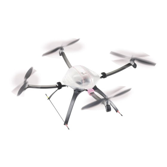
- Page 1 QuadroCopter „650“ V2 ARF MEMS Item no.: 27 51 00 Operating Instructions Version 10/11 ...
-
Page 2: Table Of Contents
Table of Contents Page Introduction ................................5 Intended Use ............................... 6 Product Description ............................. 7 Scope of Delivery ..............................8 Explanation of Symbols ............................9 Safety Information ............................... 9 a) General Information ............................9 b) Before Commissioning ..........................10 c) During Operation ............................ - Page 3 Page 11. Safety Devices ..............................33 a) Motor Protection ............................33 b) Emergency Landing ............................ 33 c) Low Voltage Monitoring ..........................34 d) Bootloader operation ........................... 34 12. LED Displays and Signal Encoder Messages ....................35 12.1. LED Displays ............................35 a) Ready to Fly ..............................
- Page 4 Page 17. The First Flight ..............................51 18. Maintenance and Repair ........................... 53 a) Regular Cleaning ............................53 b) Replacing the Rotors ........................... 53 c) Replacing a Motor ............................53 d) Replacing a Radial Arm ..........................54 e) Replacing the Complete Frame ........................54 f) Replacing the Stabiliser Plate ........................
-
Page 5: Introduction
1. Introduction Dear Customer, Thank you for purchasing this product. This product complies with the applicable statutory, national and European specifications. To maintain this status and to ensure safe operation, you as the user must observe these operating instructions! These operating instructions are part of this product. -
Page 6: Intended Use
2. Intended Use The “QuadroCopter 650 V2 ARF MEMS” is a flight model; solely designed for private use in the model making area and the operating times associated with this. This system is not suitable for other types of use. Any use other than the one described above may damage the product. -
Page 7: Product Description
3. Product Description The electric flight model “QuadroCopter 650 V2 ARF MEMS” is pre-assembled as far as possible. In the professional field, such flight devices are already used for the most diverse of tasks. The latest micro processor controlled electron- ics with position control and acceleration sensor stabilise the QuadroCopter. -
Page 8: Scope Of Delivery
4. Scope of Delivery Figure 1 1) Pre-assembled QuadroCopter 10) Rotor tips (4 pcs) 2) Hook and loop tapes (4 pcs) 11) Silicon hoses (4 pcs) 3) Screws (8 pcs) 12) End caps for radial arms (4 pcs) 4) Rotors 2x left Not displayed: Operating instruction in German (manual), operat- 5) Rotors 2x right ing instructions in English, French and Dutch on CD, aerial tubes,... -
Page 9: Explanation Of Symbols
5. Explanation of Symbols The symbol with the exclamation mark points out particular dangers associated with handling, function or operation. The “arrow” symbol indicates special advice and operating information. 6. Safety Information In case of damage caused by non-compliance with these safety instructions, the warranty/guaran- tee will become void. -
Page 10: B) Before Commissioning
• Do not leave packaging material unattended. It may become dangerous playing material for children! • The product has been designed for operation in an ambient temperature of between 10°C und 40°C and under normal air humidity conditions in Central Europe in dry weather. Operation under different conditions can lead to changed (material) properties and damage to the product as a result. - Page 11 • Never expose your model or the remote control to direct sunlight or excessive heat for an extended period of time. • In the case of a severe crash (e.g. from a high altitude). the electric gyro sensors can be damaged and/or misadjusted. Therefore, full functionality must be tested before flying again without fail.
-
Page 12: Notes On Batteries And Rechargeable Batteries
7. Notes on Batteries and Rechargeable Batteries Despite the fact that handling batteries and rechargeable batteries in daily life nowadays is a matter of fact, there are still numerous dangers and problems involved. For LiPo/LiIon rechargeable batteries in particu- lar, various regulations must be observed under any circumstances due to their high energy content (in comparison to conventional NiCd or NiMH rechargeable batteries), because otherwise there is danger of explosion and fire. -
Page 13: B) Flight Battery
b) Flight Battery Attention! After the flight, the LiPo flight battery must be disconnected from the electronics system of the QuadroCopter. Do not leave the LiPo flight battery connected to the electronic system when you do not use it (e.g. during transport or storage). -
Page 14: Final Assembly Of The Quadrocopter
8. Final Assembly of the QuadroCopter a) Assembly of the Landing Legs Attach one self-adhesive rubber buffer (2) each to the four ends of the chassis reinforcement plate (1) as displayed in figure 2a, item “A”. These rub- ber buffers are used as stop buffers for the radial arm (3). - Page 15 Instead of the landing gear used for the “QuadroCopter 650”, the landing legs of the “QuadroCopter 450” may also be used. They are not included with the delivery of the “QuadroCopter 650”, but can be ordered as a spare part (see spare part list of “QuadroCopter 450”).
-
Page 16: B) Assembly Of The Rotors
b) Assembly of the Rotors The rotating direction of the rotors can be seen in the adjacent figure (bird’s eye view). The arrow on the radial arm is to be used as the indication for the direction of the model and is deemed to be “front”. Attention! As the motors are pre-assembled, the rotating direction of the rotors on the... -
Page 17: C) Receiver Connection
c) Connecting the Receiver The receiver is connected to the “X13” connection socket of the combiboard (1). A suitable connection cable (10-pin flat cable) is supplied with QuadroCopter. The connection socket “X13” has 10 contacts that are numbered from the right to the left. - Page 18 Important! Observe that the composite signal converter inputs are assigned without gaps! With a 7-channel receiver the receiver outputs 1 - 7 must be assigned in chronologically correct order with the corresponding inputs of the sum signal converter. For example, if the receiver outputs 1 - 4 and then 6 and 7 are assigned, the electronic unit would not recognise channels 6 and 7! Due to the many remote control receiver sizes and builds on the market, we cannot give any concrete installation notes for the receiver.
-
Page 19: D) Installing The Flight Battery
d) Installing the Flight Battery The flight battery is not included. Take the following steps to install the flight battery: Solder the supplied high power loading system to the connecting cable of the rechargeable battery. Always ensure correct polarity. The red electronics system cable of the QuadroCopter must be connected to the positive cable of the rechargeable battery and the black cable to the negative cable of the rechargeable battery. -
Page 20: E) Assembly Of The Upper Cover Hood
e) Assembly of the Upper Cover Hood Due to the position of the aerial pipe and the pre- drilled hole in the upper hood, the hood can only be mounted in one position. Attach the upper cover hood (1) with a rubber band (2) as shown in figure 7. -
Page 21: Checking The Configuration
9. Checking the Configuration a) General Information Please carry out the configuration of the QuadroCopter as described in this chapter. Programming of the channels is essential, since otherwise the QuadroCopter will not recognise your transmitting equipment. When you have carried this out, your QuadroCopter is ready to fly. -
Page 22: B) Programming Of Transmitter Channels (General)
b) Programming of Transmitter Channels (General) Before you begin programming, unplug the rechargeable battery, if connected, from the QuadroCopter. Also disconnect the connection cable to the PC, if connected, from the QuadroCopter. The channels must be programmed at the QuadroCopter's flight control first. LD2 (figure 8, item 1;... -
Page 23: C) Programming Of "Throttle
Important! Before switching the transmitter on, please set the throttle stick to “motors off” and all trim levers / trim sliding controllers of the pilot stick to the neutral position. Otherwise, the QuadroCopter may not recognise the transmitter after the battery is connected. Now switch on the transmitter and pull out the telescopic aerial of 27-/40 MHz remote control systems completely. -
Page 24: D) Programming Of "Yaw
d) Programming of “Yaw” Now move the yaw lever (see figure 10) to the left to full deflection and hold it there for at least one second. The QuadroCopter thus recognises the YAW chan- nel and memorises this. Move the YAW lever back to neutral position with the THROTTLE still on zero. -
Page 25: F) Programming Of "Roll
f) Programming of “Roll” Move the ROLL lever (see figure 12) to full deflec- tion for ROLL LEFT and hold it there for at least one second. The QuadroCopter thus recognises the ROLL chan- nel and memorises this. Move the ROLL lever back to neutral position, continue to leave the THROTTLE on zero. -
Page 26: G) Programme Switch For "Agility Mode
g) Programme switch for "agility mode" To programme channel 5 to activate "agility mode", a switch at the remote control transmitter must be operated twice (on - off). When programming chan- nel 5, the last position of the programmed switch means that the "agility mode"... -
Page 27: H) Setting The Flight Mode
h) Setting the Flight Mode The QuadroCopter offers three different flight modes. • Beginner (suitable for novices) • Sport (suitable for proficient QuadroCopter pilots; lower axis limits and higher dynamics) • User (flight parameters adjustable with PC software, see chapter “configuration with PC software”) Before flight operation, set the respective DIP switch to set the desired flight mode ("Beginner", "Sport"... -
Page 28: I) General Notes On The Function "Agility Mode
i) General Notes on the Function "Agility Mode" The flight control "QC 09" installed in the QuadroCopter has high-quality MEMS sensors installed for flight position stabilisation. This leads to relatively easy to control flight characteristics similar to those of a coax helicopter. The QuadroCopter agility is limited by these sensors, however. -
Page 29: K) Connections And Signal Elements Of The Flight Control "Qc 09
k) Connections and Signal Elements of the Flight Control "QC 09" Figure 13 Interface to the expansion boards Interface to the motor drivers DIP switches 1-6 for mode changing X6 / X7 No function No function Serial interface for programming and status message output Second serial interface for external control commands (up-to-date information on this are available in the download centre at www.conrad.com) No function... -
Page 30: L) Possible Flight Modes
l) Possible Flight Modes Mode Throttle Pitch Roll... -
Page 31: Before Each Use
Before Each Use a) Checking the Connections Check all screws for tightness before transport and flights. Vibration during transport and flight may cause screws to loosen. Due to this, you need to conduct a thorough pre-flight check just as for a real helicopter. b) Checking Movable Parts Always check all movable parts and all parts with bearings for unobstructed movement before flying. - Page 32 If you do not set the neutral position , the QuadroCopter will use either the factory settings or the last saved value! It is very important that you set the neutral position of the QuadroCopter as precisely as possible. For this, it is necessary to set the neutral position on a completely horizontal base.
-
Page 33: Safety Devices
Safety Devices The QuadroCopter has a number of safety facilities to protect the model from damage or reduce possible damage to a minimum. The protective mechanisms are indicated via LED or signal encoders. For this, please observe the follow- ing chapter 12 "LED Displays and Acoustic Messages of the Signal Encoder". -
Page 34: C) Low Voltage Monitoring
c) Low Voltage Monitoring The QuadroCopter constantly monitors the voltage of the connected battery. When the battery's charge end voltage is reached (threshold value approx. 9.4 V), the red LED (LD2) starts to flash quickly. At the same time, the signal encoder starts to buzz at a slow rhythm. -
Page 35: Led Displays And Signal Encoder Messages
LED Displays and Signal Encoder Messages 12.1 LED Displays If the flight control determines any malfunctions during self-test, motor start or in flight, these malfunctions are visually indicated via the LED displays of LD1 and LD2. LD1 and LD2 are located on the flight control PCB (also see figure 8). The following LED codes are possible: a) Ready to Fly After you have plugged in the flight battery and before starting the motors, the green LED lights up and the red LED is... -
Page 36: F) Impaired Radio Link During Flight Operation
f) Impaired Radio Link during Flight Operation You want to take off and the engines are already switched on or during flight operation. The red and the green LEDs flash slowly at the same time and indicate a faulty radio link. Possible causes: Receiver crystal has fallen out of the base, receiver crystal is defective, receiver aerial has broken off. -
Page 37: Acoustic Signal Encoder Messages
12.2 Acoustic Signal Encoder Messages If the flight control determines any malfunctions during self-test, motor start or in flight, these malfunctions are indicated acoustically via signal encoder. The signal encoder is located on the flight control PCB (also see figure 8). The following signal codes are possible: Gyro error at zero reconciliation roll, 1 x brief beep, then 1 s break... -
Page 38: Combiboard "Qc08" Information
Combiboard “QC08” Information a) Connection Contacts or Jumper of the Combiboard PAD1: Plus soldering connection for supply voltage (+) PAD2: Minus soldering connection for supply voltage (-) LD1: Green LED indicator LD2: Red LED indicator X1: Jumper for buzzer X2: Jumper for light mode X3: Connection contacts for LED or LED-strips 1 - 4 X4: Connection contacts for LED or LED-strips 5 - 8... -
Page 39: B) Composite Output Signal
b) Composite Signal Output The composite signal converter outputs the formed composite signal (SuS) at the upper contact of the “X14” connection. This composite signal consists of so many single signals as measured at the inputs. PAD1 For example, if a 6-channel receiver is used, the composite signal also has 6 channels. -
Page 40: D) Interface Connection
Behaviour in case of reception interferences The composite signal converter measures the signal quality and thus also recognises reception interferences. Since channels 1 - 4 are mainly used for general control of models, they are specifically described. Interferences on channels 1 - 4 For these channels, verification of a valid pulse width (between 1 and 2 ms) is performed. -
Page 41: Light & Sound Function
Light & Sound Function a) General Information The combiboard has eight LED outputs (“L1” to “L8”), and three digital inputs (“IN-1”, “IN-2”, “IN-3”) and an external RC input (“PPM”) in addition to the composite signal converter. Triggering of the LED outputs can be configured via 7 different modes. The electronics either generate a fixed pattern on the outputs or the outputs are switched depending on the input signals. - Page 42 RC Input: Using the RC input, you may switch every light mode to three different switching states. Use a switch on the transmitter with a centre position (high, neutral, low) or a slider or rotary control. For switching the light mode, you may use channels 5 –...
-
Page 43: B) Selecting The Light Mode
b) Selecting the Light Mode You can now set 7 light modes using the jumper (“X2”). Depending on the desired mode, the different contacts must be connected with a jumper. Set the following jumpers for the following modes: Mode 1: No jumper BUZ1 Mode 2: Jumper 1 - 2 Mode 3: Jumper 3 - 4... -
Page 44: C) Selecting The Rc Input
c) Selecting the RC Input The desired RC input for switching the light effect can be set using the jumper SW1. Always connect the upper and lower contacts with the jumper. Assignment is as follows: Servo selection 1 = channel 8 Servo selection 2 = channel 7 Servo selection 3 = channel 6 Servo selection 4 = channel 5... -
Page 45: D) Connecting The Led Strips/Leds
d) Connecting the LED Strips/LEDs The combiboard offers the possibility of connecting up to eight LED strips with an operating voltage of 12 V and a maximum power intake of 1 A/per strip. Even if the MOSFET switching outputs (FDS6890A) can resist up to 7.5 A, it is recommended not to put more than 1 A on the individual outputs for board layout and cooling reasons. -
Page 46: E) Buzzer Configuration
e) Buzzer Configuration The buzzer can be switched on or off with the jumper (“X1”). BUZ1 When contacts 1 and 2 are connected with a jumper, the buzzer is off. When contacts 2 and 3 are connected with a jumper, the buzzer is on and outputs signals ac- cording to the modes table. -
Page 47: Combiboard Pc Connection
Combiboard PC Connection The Combiboard has a serial interface like the control board of the QuadroCopter. The electronics can communicate with a computer via those interfaces. Using the jumper “X11”, the serial interface of the combiboard can either communicate with the control board of the QuadroCopter (2nd internal interface) via the 26-core interface cable or be switched to the interface connection “X12”. -
Page 48: Information For First Take-Off
Information for First Take-Off a) General Handling A QuadroCopter is essentially equipped with the handling of a normal helicopter. The differences, however, are in the detail. For helicopters, the torque balance is stabilised by special gyros (in the yaw function). For this, there are two different systems: “Normal gyros”... -
Page 49: C) Cutting The Motor
c) Cutting the Motor The running motors can be turned off as follows: • THROTTLE to zero, YAW to full deflection to the right, PITCH and ROLL to neutral • Rotors are stopping • Red LED is off, green LED is permanently lit (“ready to fly”) d) Hover Flight For a simpler and consistent explanation of steering , classic terminology is used here as well. -
Page 50: F) Pitch
f) Pitch “Pitch” denotes the movement around the cross axis which can be compared to the nodding of a head. Through this, the QuadroCopter gains flight speed forwards or backwards or decelerates. Point (1) indicates “forwards”. Figure 26 g) Roll “Roll”... -
Page 51: The First Flight
The First Flight The first flight test should be made with the sensors on (function "agility mode" off) to get used to the flight characteristics of the new flight control. After getting used to them, activate the "agility mode" function on your remote control transmitter at a sufficient distance from the ground. - Page 52 Important! Never take off with a badly trimmed flight device. Then increase the throttle until the QuadroCopter is at least one meter above the ground. Carefully try to correct a gentle drift with the trim levers for yaw, pitch or roll. As soon as the QuadroCopter is high enough in the sky, decrease the throttle until the QuadroCopter hovers.
-
Page 53: Maintenance And Repair
Maintenance, Care and Repair a) Regular Cleaning The QuadroCopter is a very simple but nonetheless well-designed flying device. There are no mechanical parts that need to be lubricated or require special maintenance. However, after each flight operation you should clean the QuadroCopter of possible dirt (grass blades, dust etc.). -
Page 54: D) Replacing A Radial Arm
Attention! If the colours of the connecting cables are swapped, the rotating direction of the motors will change. This will cause the model to malfunction. As a precaution, compare the configuration of the other motors with that of the replaced motor. Loss of guarantee/warranty! •... -
Page 55: Disposal
Disposal a) General Information At the end of its service life, dispose of the product according to the relevant statutory regulations. b) Batteries and Rechargeable Batteries As the end user, you are required by law (Battery Ordinance) to return all used batteries/rechargeable batteries. Disposing of them in the household waste is prohibited! Batteries/rechargeable batteries containing hazardous substances are marked with the adjacent icon to ... -
Page 56: Technical Data
Technical Data Dimensions Diameter without rotors: ..........650 mm Total expanded height: ..........285 mm Weight: ............... Approx. 1,100 g (including rechargeable battery) Max. take-off weight: ..........2,000 g (must not be exceeded!) Electrical Data Supply voltage: ............9 - 12 V (3 cell LiPo battery) Recommended flight battery: ........ - Page 57 Interface Assignment Connection X5 of the Flight Control Pin 1: Vbat Pin 2: Vbat Pin 3: SA4 (switching channel 4, controlled by servo channel 8) Pin 4: SA3 (switching channel 3, controlled by servo channel 7) Pin 5: SA2 (switching channel 2, controlled by servo channel 6) Pin 6: SA1 (switching channel 1, controlled by servo channel 5) Pin 7:...
- Page 60 Legal Notice These operating instructions are a publication by Conrad Electronic SE, Klaus-Conrad-Str. 1, D-92240 Hirschau (www.conrad.com). All rights including translation reserved. Reproduction by any method, e.g. photocopy, microfilming, or the capture in electronic data processing systems require the prior written approval by the editor. Reprinting, also in part, is prohibited. These operating instructions represent the technical status at the time of printing.
Need help?
Do you have a question about the 650 and is the answer not in the manual?
Questions and answers