Table of Contents
Advertisement
Quick Links
Advertisement
Table of Contents

Related Manuals for Keysight M9360A


Summary of Contents for Keysight M9360A
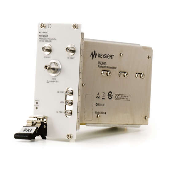
- Page 1 Service Guide Keysight M9360A PXI Attenuator/Preselector 100 KHz to 26.5 GHz...
- Page 3 OR OF ANY INFORMATION CONTAINED rights customarily provided to the HEREIN. SHOULD KEYSIGHT AND THE public to use, modify, reproduce, © Keysight Technologies 2010 - 2013 USER HAVE A SEPARATE WRITTEN release, perform, display, or disclose No part of this manual may be...
- Page 4 This Keysight products are designed for use properly-grounded power receptacle. product must be used in a normal with electrical signals that are rated...
- Page 5 Use a dry To return unwanted products, contact cloth or one slightly dampened with The CE mark is a registered trademark your local Keysight office, or for more water to clean the external case parts. of the European Community. information see Do not attempt to clean internally.
-
Page 6: Table Of Contents
Power up the Controller Software Installation Overview Step 3: Install the Module Recommended Practices for Temperature Control Module Installation Procedure Agilent M9360A PXI Attenuator/Preselector Front Panel Features Front Panel Connectors Front Panel LEDs High-Level Diagnostic Tools, Processes and References Specifications... -
Page 8: Service Guide Introduction
(page 41) you can use to record your performance test findings. Related Documentation In addition to this Service Guide, the related documentation for the M9360A module includes: Startup Guide: Provides instructions to unpack, inspect, install (software and hardware), perform instru- ment connections, verify operability, and troubleshoot problems. -
Page 9: Documentation Map
Service Guide Introduction Documentation Map Agilent M9360A PXI Attenuator/Preselector Service Guide... -
Page 10: Getting Started
Closely follow the startup process flow in this document. Deviating from the sequence can cause unpredictable system behavior, damage your system, and may cause personal injury. Step 1: Unpack Step 2: Install Drivers and Software and Inspect Step 3: Install Module Agilent M9360A PXI Attenuator/Preselector Service Guide... -
Page 11: Step 1: Unpack And Inspect The Module
1 This is the required disk space for installation. Typically, less disk space is required for operation than is required for installation. 2 .NET Framework Runtime Components are installed by default with Windows 7 and Vista. Therefore, you may not need this amount of disk space. Agilent M9360A PXI Attenuator/Preselector Service Guide... -
Page 12: Hardware Requirements
1. Install the Agilent IO Libraries Suite from the Agilent IO Libraries Suite CD (E2094-60003) provided in your ship kit. Follow the installer prompts to install the IO libraries. 2. Install the M9360A product software: a. Using the Agilent M9392A PXI Vector Signal Analyzer Software and Product Information CD (M9392-10002), launch the installer. - Page 13 3. Power down the host PC. If you are using a remote controller, Shut Down the PC BEFORE you power down the chas- sis. When you restore power, power up the chassis BEFORE you power up the PC. Agilent M9360A PXI Attenuator/Preselector Service Guide...
-
Page 14: Step 3: Install The Module
4. Before inserting the module into the chassis, back the mounting screws out to ensure that there is no inter- ference between the screws and the mounting rails. 5. Holding the module by the injector/ejector handle, slide it into an available PXI (or hybrid) slot, as shown in the figure below. Agilent M9360A PXI Attenuator/Preselector Service Guide... - Page 15 11. If you are using a PCIe Cable Interface, such as the Agilent M9021, connect the Cable Interface in the chassis to the PC host per the instructions that came with the Cable Interface. 12. Power up the PXI chassis. 13. Reboot the PC host. Agilent M9360A PXI Attenuator/Preselector Service Guide...
-
Page 16: Agilent M9360A Pxi Attenuator/Preselector Front Panel Features
The front panel LED behavior is STATUS This LED indicates the overall health of the M9360A and is a summary of valid only when the soft the following LEDs, covering the power supplies and other hardware operations. The M9360A has extensive built-in-test (BIT) and specific... -
Page 17: High-Level Diagnostic Tools, Processes And References
High-Level Diagnostic Tools, Processes and References This section provides high-level tools, processes, and references to help you diagnose problems with your module. Before attempting to diagnose the Agilent M9360A, make sure you have followed the necessary startup instructions (see "Getting Started"... - Page 18 Total Loss – displays the sum of the estimated Port Loss, Preselector Loss, and Attenuator Loss. The values for Step Attenuator, Preselector (Enabled and Frequency), and RF Path reflect the settings you've made in the SFP interface. For reference, refer also to the Block Diagram (page 18). Agilent M9360A PXI Attenuator/Preselector Service Guide...
-
Page 19: Front Panel Leds
Initialize function/method has been called, using the application programming interface (API). Description STATUS This LED indicates the overall health of the M9360A and is a summary of the following LEDs, covering the power supplies and other hardware operations. The M9360A has extensive built-in-test (BIT) and specific issues can be iden- tified by observing the status indicator on the front panel. -
Page 20: Operational Check
To use a single power meter in place of two power meters and sensors, characterize the PSG output power at the different frequencies and then connect the PSG output directly to the M9360A RF IN. Connect the power sensor to the outputs listed in the procedure below. - Page 21 3. Disconnect cables from RF IN, RF 1 OUT, RF 2 OUT, LO IN, LO 1 OUT, and LO 2 OUT 4. Under Primary Settings: a. Deselect Preselector Enabled to remove the YTF and place the M9360A in “bypass” mode (click inside the small square to remove the check mark).
- Page 22 The power splitter input. b. Connect a power sensor to one power splitter output. c. Connect the other power splitter output to the M9360A RF IN. d. Connect the second power sensor to RF 2 OUT. 8. Step the PSG frequency from 3 GHz to 26.5 GHz in 500 - MHz steps 9.
- Page 23 (page 23) to verify the module is performing according to published, fac- tory-set specifications. If you need to swap a defective module with a core replacement module from Agilent, see Module Core Replace- ment (page 37). Agilent M9360A PXI Attenuator/Preselector Service Guide...
-
Page 24: Performance Verification Tests
Test Method This test measures the insertion loss (above 10 MHz) from the M9360A RF IN port to the RF 1 OUT port. This test also measures the insertion loss (above 10 MHz) from the RF IN port to the RF 2 OUT port through the prese- lector bypass path as well as the YTF path (for reference on paths, see "Block... - Page 25 The supported models listed here assume N5245A. The VNAs specified are configured with 2.4 mm and 1.85 mm. Appropriate Cables 85133D cable kit cables and adaptors are needed to connect to the M9360A 3.5 mm female connectors. Cable 8121-1221 Coaxial cable, 3.5 mm (m) connectors, 1220 mm length...
- Page 26 Test Setup 1. Turn on the VNA and allow it to warm up for 90 minutes. 2. Install the M9360A into the PXI chassis. 3. Turn on the PXI chassis and allow it to warm up for 15 minutes. 4. Connect the cables and adaptors to the VNA so that the ends of both cables have 3.5 mm male connectors.
- Page 27 – page 41). Measure LO 2 OUT Insertion Loss 1. Disconnect the cable from LO 1 OUT on the M9360A, and connect it to LO 2 OUT on the M9360A. For reference, see the Test Configuration diagram above (see page 41).
- Page 28 Measure RF 2 OUT (bypass) Insertion Loss 1. Disconnect the cable from RF 1 OUT on the M9360A, and connect it to RF 2 OUT on the M9360A. 2. Configure the M9360A Soft Front Panel as shown in Table 9.
- Page 29 7. Record the marker value as the Measured Insertion Loss of the RF 2 OUT (bypass) path (use the Test Report Card – page 41). Measure RF 2 OUT (YTF) Insertion Loss 1. Configure the M9360A Soft Front Panel as shown in Table 11. Table 11 Parameter...
-
Page 30: Insertion Loss Below 10 Mhz
Test Method This test measures the insertion loss (below 10 MHz) of the M9360A, from the RF IN port to the RF 1 OUT port and the RF 2 OUT port when in the preselector bypass setting. This test also measures the insertion loss (below 10 MHz) from the LO IN port to the LO 1 OUT and LO 2 OUT ports. - Page 31 3. Connect the other output port of the two-resistor splitter to the RF IN port of the M9360A module, using an appropriate adaptor. 4. Connect the channel B power sensor to the RF 1 OUT port of the M9360A, using the right angle SMA and 3.5 mm (m) to 3.5 mm (m) adaptors.
- Page 32 Record the insertion loss value for RF 1 OUT in the Test Record Card (see page 41). RF IN to RF 2 OUT measurement 1. Move the Channel B power sensor to the M9360A RF 2 OUT port, using the right angle SMA and 3.5 mm (m) to 3.5mm (m) adaptors.
-
Page 33: Ytf 3 Db Bandwidth Test
Test Method This test uses a spectrum analyzer to measure relative power to determine the 3 dB bandwidth of the M9360A preselector. For this test, 3 dB YTF Bandwidth is defined as the bandwidth between the upper and lower frequen- cies where the gain of the YTF is 3 dB lower than the gain at the center frequency. - Page 34 Connect the signal analyzer 10 MHz OUT port to the signal source 10 MHz IN port. b. Connect the RF OUT of the signal source to the RF IN port of the M9360A preselector. c. Connect the spectrum analyzer to the RF 2 OUT port of the M9360A preselector.
- Page 35 5. Move the marker to the left one step. a. Record the marker amplitude as y b. Record the marker frequency as x 6. Calculate the lower 3 dB point frequency, x (assuming amplitude of y = -3 dB). Agilent M9360A PXI Attenuator/Preselector Service Guide...
- Page 36 The expanded uncertainty of measurement for this test (noted as the “Uncertainty” value provided in the Test Record Card -- see page 41) represents the standard uncertainty of measurement multiplied by the coverage factor k=2. For normal distribution, this corresponds to a coverage probability of approximately 95%. Agilent M9360A PXI Attenuator/Preselector Service Guide...
-
Page 37: Service
Service Service This section provides reference information and procedures to help you service your Agilent M9360A . In this section: Replaceable Parts (page 36) Module Core Replacement (page 37) Test Record Card (page 41) Replaceable Parts Cable Reference Agilent Part... -
Page 38: Module Core Replacement
3. Write down the serial number shown on the side shield of the defective module. You will assign this serial number to the replacement module using the Agilent M9392A Serial Number Update Utility. 4. Remove the replacement module from the box and shipping material. Agilent M9360A PXI Attenuator/Preselector Service Guide... - Page 39 NOTE: Keep the screws; extra screws are not included with the replacement module. b. Slide the shield toward the module's front panel. This aligns the engagement tabs so you can remove the shield. Agilent M9360A PXI Attenuator/Preselector Service Guide...
- Page 40 7. Attach the original side shield from the defective module to the replacement module. a. Position the side shield so that the screw tabs align with the screw holes on the module, and then slide the side shield against the front panel. Agilent M9360A PXI Attenuator/Preselector Service Guide...
- Page 41 Examples), and install it on your computer or embedded controller. b. Launch the Agilent M9392A Serial Update Utility (launch from the Start menu program group “Agi- lent Utilities”) and follow the embedded instructions for programming the serial number. Agilent M9360A PXI Attenuator/Preselector Service Guide...
-
Page 42: Test Record Card
Write the following information on a tag and attach it to the malfunctioning equipment: Name and address of owner. A P.O. box is not acceptable as a return address. Product model number (for example, M9360A). Product serial number. The serial number label is located on the side panel of the module. The serial number can also be read from the Soft Front Panel interface, but only after the hardware is installed. - Page 43 This information is subject to change without notice. © Keysight Technologies 2010 - 2013 Published in USA, January 17, 2013 M9360-90009 www.keysight.com...
Need help?
Do you have a question about the M9360A and is the answer not in the manual?
Questions and answers