
Related Manuals for Keysight M9164A


Summary of Contents for Keysight M9164A
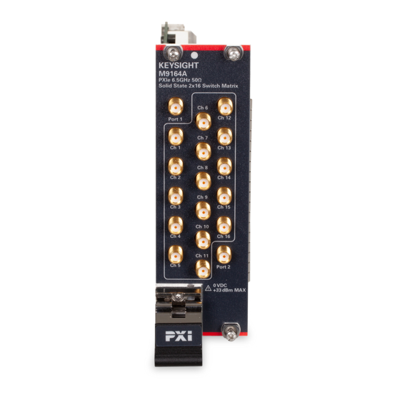
- Page 1 Keysight M9164A/B/C and M9165A/B/C PXIe Solid State Switch Module Startup and Service Guide...
- Page 2 FAR 27.401 or DFAR could result in personal injury or death. 227.7103-5 (c), as applicable in any Do not proceed beyond a WARNING technical data. notice until the indicated conditions are fully understood and met. Keysight M9164x and M9165x Startup and Service Guide...
-
Page 3: General Safety Information
Only properly trained service personnel may perform installation and service procedures. Keysight products are designed for use with electrical signals that are rated Measurement Category I and Measurement Category II, as described in the International Electrotechnical Commission (IEC) Standard IEC 60664. - Page 4 Keysight M9164x and M9165x Startup and Service Guide...
- Page 5 To maintain protection from electric shock and fire, replacement components in mains circuits — including the power transformer, test leads, and input jacks — must be purchased from Keysight. Standard fuses with applicable national safety approvals may be used if the rating and type are the same. Other components...
-
Page 6: Front And Rear Panel Symbols
This symbol is a South Korean Class A EMC Declaration. This equipment is Class A suitable for professional use and is for use in electromagnetic environments outside of the home. R-R-Kst-WN19621 R-R-Kst-WN18534 Keysight M9164x and M9165x Startup and Service Guide... -
Page 7: South Korean Class A Emc Declaration
Product Category With reference to the equipment types in the WEEE directive Annex 1, this instrument is classified as a “Monitoring and Control Instrument” product. The affixed product label is as shown below. Keysight M9164x and M9165x Startup and Service Guide... -
Page 8: Cleaning Precautions
Do not dispose in domestic household waste. To return this unwanted instrument, contact your nearest Keysight Service Center, or visit http://about.keysight.com/en/companyinfo/environment/takeback.shtml for more information. Cleaning Precautions To prevent electric shock, disconnect the instrument from mains before WARNING cleaning. Use a dry cloth or one slightly dampened with water to clean the external case parts. -
Page 9: Table Of Contents
........30 Keysight M9164x and M9165x Startup and Service Guide... - Page 10 THIS PAGE HAS BEEN INTENTIONALLY LEFT BLANK Keysight M9164x and M9165x Startup and Service Guide...
- Page 11 ......31 Figure 2-2 Using the Torque Wrench ..... .32 Keysight M9164x and M9165x Startup and Service Guide...
- Page 12 THIS PAGE HAS BEEN INTENTIONALLY LEFT BLANK Keysight M9164x and M9165x Startup and Service Guide...
- Page 13 .....16 Table 1-2 System Requirements ......19 Keysight M9164x and M9165x Startup and Service Guide...
- Page 14 THIS PAGE HAS BEEN INTENTIONALLY LEFT BLANK Keysight M9164x and M9165x Startup and Service Guide...
- Page 15 Keysight M9164A/B/C and M9165A/B/C PXIe Solid State Switch Module Startup and Service Guide Getting Started Introduction Step 1: Unpack and Inspect the M9164x/M9165x Module Step 2: Install the Software Step 3: Install the M9164x/M9165x Module Step 4: Verify the M9164x/M9165x Operation...
-
Page 16: Getting Started
M9164x/M9165x PXIe Solid State Switch Module (300 kHz to 18 GHz), installing the required software, and verifying basic module operations. If you have any inquiries after reviewing these information, contact your local Keysight Technologies representative or contact us through our website at www.keysight.com/find/PXIswitch. Product Model Description... -
Page 17: Step 1: Unpack And Inspect The M9164X/M9165X Module
(warranty information can be found at the beginning of this manual). To avoid damage when handling a module, do not touch the exposed CAUTION connector pins. Keysight M9164x and M9165x Startup and Service Guide... -
Page 18: Return For Service
Getting Started Information on preventing damage to your Keysight equipment can be found at NOTE www.keysight.com/find/tips. Return for Service Should it become necessary to return the module for repair or service, follow these steps: 1 Review the warranty information shipped with your module. -
Page 19: Step 2: Install The Software
[b] .NET Framework Runtime Components are installed by default with Windows Vista and Windows 7. Therefore, you may not need this amount of available disk space. [c] Version 2019 U1 (or later) of the Keysight IO Libraries Suite is required. Power Up the Host PC Power up the host PC to install the M9164x/M9165x software. -
Page 20: Install The Software
Connection Expert) can be downloaded from www.keysight.com/find/iosuitedownload. The Keysight Instrument Control DVD, with the above software, is no longer shipped with Keysight instruments. If you require a Keysight Instrument Control DVD, it can be ordered by contacting your local Keysight Customer Contact Center. -
Page 21: Step 3: Install The M9164X/M9165X Module
(or hybrid) slot as shown in the figure below. – Install the module into the PXI slot of the chassis by placing the module card edges into the front module guides (top and bottom). Keysight M9164x and M9165x Startup and Service Guide... - Page 22 10 Connect the System Interface Card in the chassis to the host PC. 11 Plug in and power up the PXI chassis. 12 Power up the host PC. Warm up time of 5 minutes is recommended, after cold turn-on and after power NOTE cycle. Keysight M9164x and M9165x Startup and Service Guide...
-
Page 23: Step 4: Verify The M9164X/M9165X Operation
The following procedure guides you to verify that the newly installed M9164x/ M9165x is operating correctly. 1 Run Keysight Connection Expert (from the desktop icon, or from Start > All Programs > Keysight IO Libraries Suite > Keysight Connection Expert). It displays the installed module (M9165x as shown below). -
Page 24: Figure 1-2 Launching The Sfp From Keysight Connection Expert
Getting Started Figure 1-2 Launching the SFP from Keysight Connection Expert 3 Click Connect to connect to the module. Keysight M9164x and M9165x Startup and Service Guide... -
Page 25: Figure 1-3 Connect To Instrument Dialog
Getting Started Figure 1-3 Connect to Instrument Dialog Keysight M9164x and M9165x Startup and Service Guide... -
Page 26: Figure 1-4 Sfp Verification
To verify that the module is working properly, click the desired port as shown in Figure 1-4. You can further verify the module to check if a port is connected using a network analyzer to perform RF measurement. Figure 1-4 SFP Verification Keysight M9164x and M9165x Startup and Service Guide... - Page 27 Keysight M9164A/B/C and M9165A/B/C PXIe Solid State Switch Module Startup and Service Guide Service and Maintenance Service Maintenance...
-
Page 28: Service And Maintenance
Should it become necessary to return the module for repair or service, contact your nearest Keysight Service Center. Maintenance The connectors of the module must be kept clean. Keysight recommends that the connectors be periodically inspected and cleaned if necessary. Clean the Connectors Clean connectors are essential for ensuring the integrity of RF and microwave coaxial connectors. - Page 29 Always completely dry a connector before you re-assemble or use it. 4 Re-inspect Inspect the connector again to make sure that no particles or residue are present. Keysight M9164x and M9165x Startup and Service Guide...
-
Page 30: Make Good Connections
Very light finger pressure is enough to accomplish this. 7 Ensure that the connectors are properly supported. Relieve any side pressure on the connection from long or heavy devices or cables. Keysight M9164x and M9165x Startup and Service Guide... -
Page 31: Figure 2-1 Wrench Positions
This is especially true when several devices are connected together. Hold this wrench steady Lift Device Device Correct method Incorrect method (Reduces lift on connection) (Too much lift on connection) Figure 2-1 Wrench Positions Keysight M9164x and M9165x Startup and Service Guide... -
Page 32: Figure 2-2 Using The Torque Wrench
Do not twist the head of the wrench relative to the outer conductor mating plane. If you do, you apply more than the recommended torque. Keysight M9164x and M9165x Startup and Service Guide... - Page 33 2 Use another open-end wrench to loosen the connector nut. 3 Complete the separation by hand, turning only the connector nut. 4 Pull the connectors straight apart without twisting, rocking, or bending either of the connectors. Keysight M9164x and M9165x Startup and Service Guide...
- Page 34 Service and Maintenance THIS PAGE HAS BEEN INTENTIONALLY LEFT BLANK Keysight M9164x and M9165x Startup and Service Guide...
- Page 35 This information is subject to change without notice. Always refer to the English version at the Keysight website for the latest revision. © Keysight Technologies 2020 Edition 2, August 20, 2020 M9164-90001 www.keysight.com...
Need help?
Do you have a question about the M9164A and is the answer not in the manual?
Questions and answers