Table of Contents
Advertisement
Quick Links
MOTO GUZZI WOULD LIKE TO THANK YOU
for choosing one of its products. We have compiled this booklet to provide a comprehensive overview of your vehicle's quality features. Please read it
carefully before riding the vehicle for the first time. It contains information, tips and precautions for using your vehicle. It also describes features, details
and devices to assure you that you have made the right choice. We believe that if you follow our suggestions, you will soon get to know your new vehicle
well and that it will continue to give you satisfactory service for many years to come. This booklet forms an integral part of the vehicle; should the vehicle
be sold, it must be transferred to the new owner.
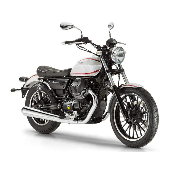
V9 Roamer - V9 Bobber
Ed. 03_05/2016 Cod. 2Q000110 (IT-FR-DE-NL-ES-EN)
Advertisement
Table of Contents

Related Manuals for MOTO GUZZI V9 Roamer 2016


Summary of Contents for MOTO GUZZI V9 Roamer 2016
- Page 1 MOTO GUZZI WOULD LIKE TO THANK YOU for choosing one of its products. We have compiled this booklet to provide a comprehensive overview of your vehicle's quality features. Please read it carefully before riding the vehicle for the first time. It contains information, tips and precautions for using your vehicle. It also describes features, details and devices to assure you that you have made the right choice.
- Page 2 The instructions in this manual have been prepared to offer mainly a simple and clear guide to its use; it also describes routine maintenance procedures and regular checks that should be carried out on the vehicle at an authorised Moto Guzzi Dealer or Workshop, The booklet also contains instructions for simple repairs.
- Page 3 Personal safety Failure to completely observe these instructions will result in serious risk of personal injury. Safeguarding the environment Sections marked with this symbol indicate the correct use of the vehicle to prevent dam- aging the environment. Vehicle intactness The incomplete or non-observance of these regulations leads to the risk of serious damage to the vehicle and sometimes even the invalidity of the guarantee The symbols illustrated above are very important.
-
Page 5: Table Of Contents
Engine stop switch..............42 Use of a new battery............. 86 System ABS................42 Checking the electrolyte level..........87 MGTC system(Moto Guzzi Controllo Trazione)......44 Charging the battery.............. 87 Opening the saddle............... 49 Long periods of inactivity............88 USB Port................49... - Page 6 Lamps..................91 Headlight adjustment............. 93 Front direction indicators............95 Rear optical unit................ 96 Rear turn indicators..............97 Rear-view mirrors..............98 Front and rear disc brake............99 Periods of inactivity..............101 Cleaning the vehicle..............103 Transport................... 105 TECHNICAL DATA..............107 PROGRAMMED MAINTENANCE..........117 Scheduled maintenance table...........
-
Page 7: General Rules
V9 Roamer - V9 Bobber Chap. 01 General rules... -
Page 8: Foreword
OR FOR SPORTING APPLICATIONS. Motorcycle care Moto Guzzi recommends using quality products for cleaning the vehicle. The use of unsuitable products can damage vehicle components. For cleaning do not use sol- vents such as "nitro thinner", "cold cleaning agents", or similar fuels, or cleaning products that contain alcohol. - Page 9 USE OF HOT WATER INTENSIFIES THE EFFECT OF THE SALT. USE ONLY PLENTY OF COLD WATER TO WASH AND REMOVE ANTI-ICING SALT USE OF HIGH PRESSURE WASHING SYSTEMS (OR STEAM CLEANERS) CAN DAMAGE THE SEALS, OIL SEALS, BRAKING SYSTEM, ELECTRICAL SYSTEM AND THE SADDLE.
-
Page 10: Carbon Monoxide
OF PLASTIC PARTS. ROTARY BRUSHES OR SPONGES WITH HARD SURFA- CES CAN MAKE SCRATCHES CHROME PARTS AND POLISHED METAL TREAT THE PARTS MADE OF CHROME, ALUMINIUM OR POLISHED STEEL IN A SPECIAL MANNER. WASH THEM WITH PLENTY OF WATER AND CAR SHAM- POO, POLISH AND REGULARLY BRIGHTEN THEM WITH POLISH PASTE, PRO- TECT THEM WITH WAXES OR SUITABLE ACID-FREE PRODUCTS (E.G. -
Page 11: Fuel
CAUTION EXHAUST EMISSIONS CONTAIN CARBON MONOXIDE, A POISONOUS GAS WHICH CAN CAUSE LOSS OF CONSCIOUSNESS AND EVEN DEATH. CAUTION CARBON MONOXIDE IS ODOURLESS AND COLOURLESS, THEREFORE IT CANNOT BE DETECTED BY SMELL, SIGHT OR OTHER SENSES. DO NOT BREATHE IN EXHAUST FUMES UNDER ANY CIRCUMSTANCES. Fuel CAUTION THE FUEL USED TO POWER INTERNAL COMBUSTION ENGINES IS HIGHLY... -
Page 12: Hot Components
IF THE VEHICLE FALLS OR IS ON A STEEP INCLINE FUEL CAN LEAK. Hot components The engine and the exhaust system components get very hot and remain in this con- dition for a certain time interval after the engine has been switched off. Before handling these components, make sure that you are wearing insulating gloves or wait until the engine and the exhaust system have cooled down. -
Page 13: Used Engine Oil And Gearbox Oil
FORMED CORRECTLY, CONTACT AN AUTHORIZED Moto Guzzi Dealer TO HAVE THE SYSTEM CHECKED. Used engine oil and gearbox oil CAUTION IT IS ADVISABLE TO WEAR PROTECTIVE IMPERMEABLE GLOVES WHEN SERVICING THE VEHICLE. THE ENGINE OR GEARBOX OIL MAY CAUSE SERIOUS INJURIES TO THE SKIN IF HANDLED FOR PROLONGED PERIODS OF TIME AND ON A REGULAR BA- SIS. -
Page 14: Battery Hydrogen Gas And Electrolyte
EYES. IN THE EVENT OF ACCIDENTAL CONTACT WITH THE EYES, RINSE THEM IMMEDIATELY WITH ABUNDANT COLD, CLEAN WATER AND SEEK MEDICAL ADVICE. KEEP OUT OF THE REACH OF CHILDREN Battery hydrogen gas and electrolyte CAUTION THE BATTERY ELECTROLYTE IS TOXIC, CORROSIVE AND AS IT CONTAINS SULPHURIC ACID, IT CAN CAUSE BURNS WHEN IN CONTACT WITH THE SKIN. -
Page 15: Reporting Of Defects That Affect Safety
Reporting of defects that affect safety Unless otherwise specified in this Use and Maintenance Booklet, do not remove any mechanical or electrical component. CAUTION SOME CONNECTORS IN THE VEHICLE MAY BE ACCIDENTALLY SWAPPED AND MAY COMPROMISE NORMAL VEHICLE OPERATION IF INCORRECTLY IN- STALLED. -
Page 17: Vehicle
V9 Roamer - V9 Bobber Chap. 02 Vehicle... -
Page 18: Arrangement Of The Main Components
Arrangement of the main components (02_01, 02_02, 02_03, 02_04) 02_01... - Page 19 02_02...
- Page 20 02_03...
- Page 21 02_04 Key - V9 Roamer/V9 Bobber: 1. Headlamp 2. Front left turn indicator 3. Instrument panel 4. Clutch lever 5. Left light switch 6. Left rear-view mirror 7. Fuel tank cap 8. Fuel tank 9. Left side fairing 10. Air filter 11.
- Page 22 14. Rear left shock absorber 15. Left silencer 16. Rear brake disc 17. Rear tone wheel 18. Rear speed sensor 19. Rear brake calliper 20. Passenger left footrest 21. Seat lock 22. Side stand 23. Left rider footrest 24. Gear shift lever 25.
-
Page 23: Dashboard
Dashboard (02_05, 02_06) Key: 1. Clutch control lever 2. Ignition switch /steering lock 3. Instruments and gauges 4. Front brake lever 5. Throttle grip 6. High beam flashing switch 7. MODE switch 8. Turn indicator switch 02_05 9. Horn button 10. -
Page 24: Light Unit
The vehicle is supplied with two keys already programmed. The instrument panel saves a maximum of four keys: contact an Official Moto Guzzi dealer to enable these keys or to disable a key that has been lost. After delivery of a new vehicle, the instru- ment panel displays the message "INSERT YOUR PERSONAL CODE"... -
Page 25: Digital Lcd Display
Digital lcd display (02_10, 02_11, 02_12, 02_13) • By turning the ignition key to "ON", the system works as follows: - all indicator lamps illuminate simultaneously for three seconds (lamp check); - it resets the position of all the needles, which afterwards go to the bottom of the scale and return to zero;... -
Page 26: Alarms
- when a maintenance interval threshold is exceeded, an icon with a spanner is shown on the LCD display. • Consult an Official Moto Guzzi Dealer to reset Service. 02_13 Alarms (02_14, 02_15) If the instrument panel or ECU detect a digital display fault, when alarm descriptions are displayed, the warning lamp MI (1) and the general alarm warning lamp (2) also illuminate. -
Page 27: Control Buttons
MOTORCYCLE TO AN Official Moto Guzzi Dealer USING A ROADSIDE ASSIS- TANCE VEHICLE. ALARM OIL SENSOR: IN CASE OF FAULT OF THE OIL PRESSURE SENSOR, THE WARNING LIGHT REMAINS ON STEADY. AS SOON AS POSSIBLE BRING THE MOTORCYCLE TO AN Official Moto Guzzi Dealership. - Page 28 Total odometer (Odometer) Unit of measurement for the counter: Km or Miles. - View: on LCD display. • This value is stored permanently. • It cannot be reset. • Selected gear cannot be displayed (gear is calculated by system). • The total odometer mode is as shown in the figure: - once the value reaches 999999, the odometer count does not reset to zero.
- Page 29 - the message "TIME" is displayed. Average speed (Average) Unit of measurement for the counter: Km/h or mph. - View: on LCD display. • This value is stored. • Press and hold the "MODE" selector to reset the counter. Disconnecting and reconnecting the battery also resets the counter.
- Page 30 Current fuel consumption (Fuel) Unit of measurement for the counter: Km/l, L/100 km, US mpg or IMP mpg - View: on LCD display. • The value is reset to 0.0 at each key-on • This parameter is displayed as shown in the figure: - the message "FUEL KM/L", "FUEL L/100"...
- Page 31 Clock (Clock) Unit of measurement for the counter: hours and minutes (hh:mm) - View: on LCD display. • This value is stored. • The data is reset when reconnecting the battery. • This parameter is displayed as shown in the figure: - the message "CLOCK"...
-
Page 32: Advanced Functions
Advanced functions (02_27, 02_28, 02_29, 02_30, 02_31, 02_32, 02_33, 02_34, 02_35, 02_36) Trip Fuel "Distance travelled in reserve" This function counts and displays the distance travelled in Km o miles with the vehicle in fuel reserve. When the low fuel warning light turns on: •... - Page 33 Backlight "Instrument backlighting adjustment" Backlighting of instruments and gauges (needles of scales and displays) can be ad- justed at three levels. This parameter may be adjusted during the initial check cycle. Press the centre of the "MODE" selector briefly to access the function. Press the "MODE" selector up or down to cycle through the three levels available: - 1 (Minimum) - 2 (Medium)
- Page 34 Gear Shift "gear shift indicator threshold" The gear shift indicator threshold is set in this mode. Press and hold the "MODE" selector to access the setting mode from the menu. Press the "MODE" button up or down to select the required setting. •...
- Page 35 User Code Modification "Change user code" The user code enables engine start even in the event of an immobiliser system fault. The user code is set by default as five zeros (00000) on a new vehicle, and the mes- sage "INSERT YOUR PERSONAL CODE" is shown on the display for ten seconds. The "USER CODE MODIFICATION"...
- Page 36 02_36 Select unit (Km/mi) "Change odometer unit of measurement" From this mode, press the "MODE" selector up or down briefly to toggle the unit of measurement used between Km and miles. The modified selection is effective on all instrument panel functions using these units of measurement. Select unit (L/100 - Km/L - US mpg - IMP mpg) "Change consumption indicator unit of measurement"...
-
Page 37: Ignition Switch
Press and hold the "MODE" selector to save the setting. The instrument panel returns to the "ODOMETER" screen. CAUTION FOR THE SAFETY OF THE RIDER AND PASSENGER, THESE PROCEDURES ARE ONLY POSSIBLE WITH THE VEHICLE AT A STANDSTILL. Ignition switch NOTE KEEP THE SPARE KEY IN DIFFERENT PLACE, NOT WITH THE VEHICLE. -
Page 38: Locking The Steering Wheel
Locking the steering wheel (02_37) TO AVOID LOSING CONTROL OF THE VEHICLE, NEVER TURN THE KEY TO "LOCK" WHILE RIDING. To lock the steering: • Turn the handlebar fully to the left. • Turn the key to «OFF». • Push in the key and turn it anticlockwise (to the left), steer the handlebar slowly until the key is set to «LOCK». -
Page 39: Switch Direction Indicators
Switch direction indicators (02_39) Move the switch to the left, to indicate a left turn; move the switch to the right to indicate a right turn. Pressing the switch deactivates the turn indicator. CAUTION IF THE WARNING LIGHT WITH ARROWS FLASHES QUICKLY, IT MEANS THAT ONE OR BOTH TURN SIGNALS LIGHT BULBS ARE BURNT OUT. -
Page 40: High/Low Beam Selector
High/low beam selector (02_40) • the switch in the central position keeps the daylight running lights, the instru- ment panel lights and the low beam on. • In the left hand position the high beam is activated. • In the right hand position the high beam flashes in case of danger or emer- gency. -
Page 41: Flasher Button
Flasher button (02_42) The HAZARD system is only available at key ON. By pressing the button, the four turn indicators and their warning lights on the panel are turned on at the same time. Press- ing again deactivates the system. The HAZARD light remains on even after extracting key but it cannot be deactivated. -
Page 42: Engine Stop Switch
Engine stop switch (02_44) CAUTION DO NOT OPERATE THE ENGINE STOP SWITCH WHILE RIDING THE VEHICLE. It acts as a safety or emergency switch. Press this switch to stop the engine. 02_44 System ABS (02_45, 02_46, 02_47) The vehicle is equipped with a locking ABS system on the front and rear wheel. A: Tone wheel B: Speed sensor •... - Page 43 Authorised Service Centre for the appropriate checks. The safety provided by the ABS does not, in any case, justify risky manoeuvres. The stopping distance may be greater, compared to a conventional vehicle equipped with traditional braking in the following conditions: •...
-
Page 44: Mgtc System(Moto Guzzi Controllo Trazione) (02_48, 02_49
0.3 - 2.00 mm (0.012 - 0.079 in) Distance between tone wheel and rear sensor 0.3 - 2.00 mm (0.012 - 0.079 in) MGTC system(Moto Guzzi Controllo Trazione) (02_48, 02_49, 02_50) The MGCT system is a device that helps the rider during acceleration in manoeuvres with the aim to increase the stability of the vehicle, especially on slippery surfaces or in conditions that can cause sudden slippage of the rear wheel. - Page 45 CAUTION THE MGCT SYSTEM DOES NOT PREVENT FALLING IN TURNS. ACCELERATING SUDDENLY WHILE THE VEHICLE IS INCLINED OR WITH THE HANDLEBARS TURNED WILL PUT THE VEHICLE IN AN UNSTABLE STATE THAT IS EXTREMELY DIFFICULT TO RECTIFY. DO NOT SPEED RECKLESSLY. LIMITS OF GRIP ARE DETERMINED BY LAWS OF PHYSICS, WHICH EVEN THE MGCT SYSTEM CANNOT OVERCOME.
- Page 46 • @@ If the system was disabled deliberately by the user (by pressing and holding the on/off button (1) with the engine running), it is highly advisable to reactivate the system as soon as possible. • If the deactivation was NOT voluntary, there is an MGCT failure: in this case you must contact an Authorised Service Centre for the diagnosis and the reactivation of the system.
- Page 47 SWITCH; AT THE NEXT KEY ON, THE MGCT SYSTEM IS ENABLED AUTOMAT- ICALLY AT THE LEVEL SET BEFORE IT WAS DEACTIVATED. CAUTION IT IS EMPHASISED THAT THE RIDING AUXILIARY SYSTEM CAN NOT CHANGE THE PHYSICAL LIMITS OF GRIP AND IS NOT A SUBSTITUTE FOR PROPER MANAGEMENT OF POWER, BOTH ON STRAIGHT STRETCHES AND IN TURNS.
- Page 48 MGCT SYSTEM CALIBRATION PROCEDURE In order to maintain the effectiveness of the MGCT system following the replacement of one or both tyres or in the case of serious wear, causing a non-compliant behaviour of the MGCT, a calibration procedure of the system must be performed as follows on a straight flat stretch of road.
-
Page 49: Opening The Saddle
Distance between tone wheel and rear sensor 0.3 - 2.00 mm (0.012 - 0.079 in) Opening the saddle (02_51, 02_52) • Rest the vehicle on its stand. • Insert the key in the saddle lock. • Turn the key clockwise by pressing slightly the centre of the saddle rear part so that the hook is easily released;... - Page 50 TO AVOID THAT WATER AND/OR HUMIDITY CAN DAMAGE THE USB PLUG, DO NOT CONNECT ANY DEVICES IN CASE OF RAIN. THE SUPPLIED USB SOCKET IS COMPATIBLE WITH THE DEVICES OF THE FOLLOWING BRANDS: Apple iPhone, Apple iPod, Apple iPod Nano, Apple iPod Touch, Blackberry Pearl, Blackberry 8xxx IS NOT COMPATIBLE WITH THE DE- VICES FOR THE PRODUCTS OF MOTOROLA.
-
Page 51: Identification
Identification (02_53, 02_54) Write down the chassis and engine number in the specific space in this booklet. The chassis number is handy when purchasing spare parts. CAUTION THE MODIFICATION OF THE IDENTIFICATION CODES IS A SERIOUS PUNISH- ABLE CRIME. HOWEVER, THE LIMITED WARRANTY FOR NEW VEHICLES WILL BE VOID IF THE VEHICLE IDENTIFICATION NUMBER (VIN) HAS BEEN MODI- FIED OR NOT PROMPTLY DETERMINED. - Page 52 ENGINE NUMBER The engine number is stamped on the left side, close to the engine oil level check cap. Engine No..... 02_54...
-
Page 53: Use
V9 Roamer - V9 Bobber Chap. 03... -
Page 54: Checks
THE VEHICLE, FOR CORRECT AND SAFE OPERATION. FAILURE TO DO SO MAY LEAD TO SEVERE PERSONAL INJURY OR VEHICLE DAMAGE. DO NOT HESITATE TO CONTACT AN Official Moto Guzzi Dealer IF YOU DO NOT UN- DERSTAND HOW SOME CONTROLS WORK OR IF MALFUNCTIONING IS DE- TECTED OR SUSPECTED. - Page 55 brake pads for wear. If necessary top-up with brake fluid. Throttle grip Check that the throttle functions smoothly and can be fully opened and closed in all steering positions. Adjust and/or lubricate necessary. Engine oil Check and/or top-up as required. Wheels/ tyres Check that tyres are in good conditions.
- Page 56 Replace bulbs or repair any faults devices noted. Transmission oil - Guzzi Check. Should top-up be necessary, please refer to an authorised Moto Guzzi repair shop. Tone wheels Check that the tone wheels are perfectly clean good...
-
Page 57: Refuelling
Refuelling (03_02, 03_03) To refuel: • Turn the cap anticlockwise and remove CAUTION ALWAYS USE PETROL WITH A MAXIMUM OF 10% BIOETHANOL CONTENT 03_02 (E10). DO NOT USE PETROL WITH AN ETHANOL CONTENT HIGHER THAN 10%; THIS USE COULD DAMAGE THE FUEL SYSTEM COMPONENTS AND/OR COMPRO- MISE ENGINE PERFORMANCE. -
Page 58: Rear Shock Absorbers Adjustment
15±0.5 l (3.30±0.11 UK gal; 3.96±0.13 US gal) Fuel tank reserve 4±0.5 l (0.88±0.11 UK gal; 1.06±0.13 US gal) • Refuel. After refuelling: CAUTION THE TANK MUST ALWAYS BE CLOSED CORRECTLY BY TIGHTENING THE CAP CLOCKWISE UNTIL IT LOCKS INTO PLACE. MAKE SURE THE CAP IS TIGHTLY CLOSED. -
Page 59: Front Fork Adjustment
FOR PROPER VEHICLE STABILITY IT IS ALWAYS A GOOD IDEA TO MAKE 03_05 SURE THAT BOTH SHOCK ABSORBERS ARE SET TO THE SAME POSITION. IF NECESSARY, CONTACT AN Official Moto Guzzi Dealership. Front fork adjustment (03_06) Carry out the following checks regularly: Operating the front brake lever, press the handlebar repeatedly to send the fork fully down. -
Page 60: Clutch Lever Adjustment
Clutch lever adjustment (03_07, 03_08) Adjustment clutch when the engine stops or the vehicle tends to move forward even when clutch lever is operated and the gear engaged, or if the clutch "slides", resulting in acceleration delay considering the engine revs. •... -
Page 61: Running In
8. Refit he protection casing (1) 9. If after the adjustment in point 3 it is not possible to ascertain the condition of "point 6", contact an Authorised Moto Guzzi Dealer to verify the proper operation of the clutch control. -
Page 62: Moving Off / Riding
TO PREVENT THE RISK OF INJURY TO YOURSELF OR OTHERS AND/OR DAM- AGE TO THE VEHICLE, TAKE THE YOUR MOTORCYCLE TO AN AUTHORISED Moto Guzzi DEALER AT THE SPECIFIED MILEAGE INTERVALS TO HAVE THE CHECKS LISTED IN THE MAINTENANCE SCHEDULE TABLE CARRIED OUT. -
Page 63: Parking
Parking It is very important to select an adequate parking spot, in compliance with road signals and the guidelines described below. CAUTION PARK ON SAFE AND LEVEL GROUND TO PREVENT THE MOTORCYCLE FROM FALLING. DO NOT LEAN THE VEHICLE AGAINST A WALL OR LAY IT ON THE GROUND. ENSURE THAT THE VEHICLE AND, IN PARTICULAR, PARTS OF THE VEHICLE WHICH MAY BECOME HOT (ENGINE, EXHAUST SYSTEM, BRAKE DISCS) ARE NOT A HAZARD TO PERSONS OR CHILDREN. - Page 64 If the noise produced by the exhaust system increases, get immediately in touch with the Dealer or with a Moto Guzzi authorised repair shop. NOTE DO NOT TAMPER WITH THE EXHAUST SYSTEM.
-
Page 65: Stand
Stand (03_09, 03_10, 03_11) BEFORE SETTING OFF, MAKE SURE THE STAND HAS BEEN COMPLETELY RETRACTED TO ITS POSITION. DO NOT REST THE RIDER OR PASSENGER WEIGHT ON THE SIDE STAND. THE SIDE STAND MUST ROTATE FREELY. IF NECESSARY GREASE THE JOINT. -
Page 66: Suggestion To Prevent Theft
03_10 A safety switch (2) is installed on the side stand (1) to inhibit ignition or to stop the engine when a gear is engaged and the side stand (1) is lowered. 03_11 Suggestion to prevent theft CAUTION WHEN USING A DISC LOCKING DEVICE, PAY UTMOST ATTENTION TO RE- MOVE IT BEFORE RIDING. -
Page 67: Safe Driving
NEVER leave the ignition key in the lock and always use the steering lock. Park the vehicle in a safe place such as a garage or a place with guards. Whenever possible, use an additional anti-theft device. Make sure all vehicle documents are in order and the road tax paid. -
Page 68: Basic Safety Rules
6. If the motorcycle is used on roads covered with sand, mud, snow mixed with salt, etc., clean the brake discs frequently with a mild detergent in order to prevent abrasive particles from building up inside the holes, which can result in early brake pads wear. CAUTION ALWAYS RIDE WITHIN YOUR LIMITS. - Page 69 The stand is designed to support the weight of the vehicle and a small additional weight, which does not include the rider and passenger. Mounting into driving position, with the side stand in place, is permitted only to prevent the possibility of the vehicle falling or overturn, and does not indicate the possibility for the rider and passenger's weight to be placed on the side stand.
- Page 70 CAUTION BAGGAGE OR OBJECTS ATTACHED TO THE REAR PART OF THE VEHICLE CAN CREATE AN OBSTACLE DURING MOUNTING AND DISMOUNTING FROM THE VEHICLE. IN ALL CASES, THINK AHEAD AND MOVE YOUR RIGHT LEG CAREFULLY, AS IT WILL HAVE TO AVOID AND CLEAR THE REAR PART OF THE VEHICLE (IN- CLUDING BAGGAGE AND THE TAIL FAIRING) WITHOUT CAUSING LOSS OF BALANCE.
- Page 71 • Have the passenger open the two passenger foot pegs. • Show the passenger how to mount the vehicle. • Use your left foot to push on the side stand and make it fully return to its position. DISMOUNTING • Select an appropriate parking spot.
- Page 72 DO NOT PLACE YOUR WEIGHT UPON THE SIDE STAND. • Lean the motorcycle until the stand touches the ground. • Correctly grip the handlebar, and dismount from the vehicle. • Turn the handlebar completely to the left. • Place the passenger footrest in its place. CAUTION MAKE SURE THE VEHICLE IS STABLE.
-
Page 73: Maintenance
V9 Roamer - V9 Bobber Chap. 04 Maintenance... -
Page 74: Foreword
In general terms, scheduled maintenance can be carried out by the owner; however, some operations may require specific tools and technical training. For periodic main- tenance, servicing or technical advice, contact an Official Moto Guzzi Dealer for prompt and accurate service. - Page 75 To check: THE ENGINE MUST BE WARM TO CHECK OIL LEVEL AND THE FILLER PLUG / DIPSTICK FULLY SCREWED IN. IF YOU CHECK LEVEL WHEN THE ENGINE IS COLD, OIL LEVEL COULD TEM- PORARILY DROP BELOW THE 'MIN' MARK. THIS IS NOT INDICATIVE OF A PROBLEM PROVIDED THAT IT IS NOT ACCOM- 04_02 PANIED BY THE GENERAL ALARM WARNING LAMP ILLUMINATING AND THE MESSAGE "ALARM OIL PRESSURE"...
-
Page 76: Engine Oil Top-Up
CAUTION DO NOT GO BEYOND THE "MAX" AND BELOW THE "MIN" LEVEL MARK TO AVOID SEVERE ENGINE DAMAGE. Engine oil top-up (04_03) Fill with engine oil as required: • Unscrew and remove the filler plug. DO NOT ADD ADDITIVES OR ANY OTHER SUBSTANCES TO THE OIL. 04_03 When using a funnel or any other element, make sure it is perfectly clean. -
Page 77: Engine Oil Change
Engine oil change (04_04, 04_05, 04_06) CHANGING ENGINE OIL AND ENGINE OIL FILTER CAN PROVE DIFFICULT IF YOUR ARE INEXPERIENCED. TAKE YOUR VEHICLE TO AN Official Moto Guzzi Dealer IF NECESSARY. IF YOU WISH TO PERFORM THESE OPERATIONS YOURSELF, FOLLOW THESE INSTRUCTIONS. - Page 78 • Place a recipient with a capacity of at least 2000 cm³ (122.05 cu.in) under the drain plug (1). • Unscrew and remove the drainage plug (1). • Drain the oil into the container; allow several minutes for oil to drain out com- pletely.
-
Page 79: Bevel Gear Pair Oil Level
• Undo the two screws (3) and remove the cover (4). • Remove the engine oil filter (5). NOTE NEVER REUSE AN OLD FILTER. 04_06 • Spread a thin layer of oil on the sealing ring (6) of the new engine oil filter. •... -
Page 80: Gearbox Oil Level
IT IS ALSO RECOMMENDED TO REPLACE SUCH WASHER AT AN AUTHOR- ISED Moto Guzzi Dealer. CAUTION TO TOP-UP OR CHANGE THE OIL IN THE CARDAN SHAFT TRANSMISSION UNIT, CONTACT AN Official Moto Guzzi Dealer. Gearbox oil level CAUTION THE GEARBOX OIL MUST BE CHECKED AND CHANGED BY AN Official Moto... -
Page 81: Tyres
Tyres (04_08, 04_09, 04_10) This vehicle is fitted with tyres without inner tubes (Tubeless). CAUTION TRACTION CONTROL (MGCT) IS SET, AT THE END OF THE PRODUCTION OF THE VEHICLE, ON LEVEL «2» AND MUST BE KEPT ACTIVE FOR THE ENTIRE RUNNING PERIOD, TO ALLOW THE CORRECT ADJUSTMENT OF THE TYRES TO ASPHALT CONDITIONS. - Page 82 CHECK THE SURFACE CONDITION AND WEAR BECAUSE POOR TYRE CON- DITION COULD COMPROMISE GRIP AND HANDLING OF THE VEHICLE. SOME TYRE TYPES APPROVED FOR THIS VEHICLE FEATURE WEAR INDICA- TORS. THERE ARE SEVERAL TYPES OF WEAR INDICATORS. CONSULT YOUR DEAL- ER ON METHODS TO CHECK FOR WEAR.
-
Page 83: Spark Plug Dismantlement
04_10 Spark plug dismantlement CAUTION FOR REMOVAL, CHECK, AND REPLACEMENT OF THE SPARK PLUGS CON- TACT AN OFFICIAL Moto Guzzi Dealer. Removing the sides (04_11) • Remove the saddle. •... -
Page 84: Removing The Air Filter
The left hand side fairing (2) can only be detached, as is kept connected to the frame by the saddle lock release cable. Removing the air filter CAUTION TO REMOVE, CHECK AND REPLACE THE AIR FILTER, CONTACT AN Official Moto Guzzi Dealer. Checking the brake oil level (04_12, 04_13) FRONT BRAKE CHECK •... -
Page 85: Braking System Fluid Top Up
• Check brake pads and discs for wear. If the brake pads and/or brake discs do not have to be replaced, have the braking system checked at an Official Moto Guzzi Dealership. REAR BRAKE CHECK • Keep the vehicle upright so that the fluid in the reservoir is at the same level as the plug. -
Page 86: Use Of A New Battery
Use of a new battery (04_14, 04_15) REMOVING THE BATTERY RESETS THE DIGITAL CLOCK AND THE TRIP JOUR- NAL FUNCTIONS. • Make sure the ignition switch is set to 'KEY OFF'. • Remove the rider saddle. • Remove the right hand side fairing. •... -
Page 87: Checking The Electrolyte Level
• Put the battery away on a level surface, in a cool and dry place. • Place the fixing bracket (2) and refit the screws (1). • Refit the left side fairing. • Refit the rider saddle. CAUTION UPON REFITTING, CONNECT THE LEAD TO THE POSITIVE TERMINAL (+) FIRST AND AFTERWARDS THE LEAD TO THE NEGATIVE TERMINAL (-). -
Page 88: Long Periods Of Inactivity
• Connect the battery to the battery charger. CAUTION WHEN RECHARGING OR USING THE BATTERY, BE CAREFUL TO HAVE THE ROOM ADEQUATELY AIRED. DO NOT BREATH GASES RELEASED WHEN THE BATTERY IS RECHARGING. Switch on the battery charger. Characteristic CHARGE MODES Recharge - Ordinary Electric Current - 1.8A Time - 8-10 hours... -
Page 89: Fuses
CHECKING AND CLEANING TERMINALS AND LEADS • Partially remove the battery from its housing. • Check that the cable terminals and battery leads are: - in good conditions (not corroded or covered by deposits); - covered by neutral grease or petroleum jelly. Fuses (04_16, 04_17, 04_18, 04_19) CAUTION DO NOT REPAIR FAULTY FUSES. - Page 90 To check: • Set the ignition switch to 'OFF' to avoid an accidental short circuit. • Remove the saddle. • Remove the fuse box cover. • Take out one fuse at a time and check if the filament is broken. •...
-
Page 91: Lamps
ABS FUSE DISTRIBUTION A) ABS Control unit (20 A). B) Spare fuses (20 A). 04_19 Lamps (04_20, 04_21, 04_22) CAUTION BEFORE REPLACING A BULB, TURN THE IGNITION SWITCH TO «KEY OFF» AND WAIT A FEW MINUTES FOR THE BULB TO COOL OFF. WEAR CLEAN GLOVES OR USE A CLEAN DRY CLOTH TO REPLACE THE BULB. - Page 92 BULB LAYOUT In the headlamp there are: - one high beam / low beam bulb (1) (upper); - one tail light bulb (2) (lower); FRONT HEADLAMP BULB REPLACEMENT • Rest the vehicle on its stand. • Remove the complete parabole from the headlight body by undoing the screw 04_20 (3).
-
Page 93: Headlight Adjustment
TAIL LIGHT BULB • Pull out the tail light bulb holder (7) from its seat. • Remove the bulb (2) and replace it with another of the same type. • Check the proper insertion of the bulb in the bulb holder. 04_22 Headlight adjustment (04_23, 04_24, 04_25) NOTE... - Page 94 In order to carry out vertical adjustment of the light beam: • Stand the motorcycle in a vertical position. • Slightly loosen the headlight fixing screws (1), and move the light beam man- ually to the desired position. • Once the adjustment is finished tighten the screws (1). 04_24 After adjusting: NOTE...
-
Page 95: Front Direction Indicators
Front direction indicators (04_26, 04_27) • Rest the vehicle on its stand. • Loosen and remove screw (1). NOTE REMOVE THE PROTECTION GLASS WITH CAUTION SO AS NOT TO BREAK THE FITTING TOOTH. 04_26 • Remove the protective glass (2). CAUTION UPON REFITTING, POSITION THE PROTECTIVE GLASS CORRECTLY IN ITS POSITION. -
Page 96: Rear Optical Unit
NOTE IF THE BULB HOLDER «4» IS STICKS OUT ITS FITTING, INSERT IT AGAIN COR- RECTLY BY MATCHING THE BULB HOLDER RADIAL OPENING WITH THE SCREW SEAT. Rear optical unit (04_28, 04_29, 04_30) • Rest the vehicle on its stand. •... -
Page 97: Rear Turn Indicators
• Press bulb (3) slightly and turn it anticlockwise. • Pull the bulb (3) out of its fitting. • Insert a bulb of equal rating in the bulb holder making the two guiding pins coincide with their guides on the bulb holder. •... -
Page 98: Rear-View Mirrors
• Press bulb (3) slightly and turn it anticlockwise. • Pull the bulb (3) out of its fitting. NOTE INSERT THE BULB IN THE BULB HOLDER SO THAT THE TWO GUIDING PINS COINCIDE WITH THEIR GUIDES ON THE BULB HOLDER. •... -
Page 99: Front And Rear Disc Brake
Rear-view mirrors removal: • Rest the vehicle on its stand. • Loosen the locking nut. • Slide up and remove the complete rear-view mirror unit. Repeat the procedure to remove the other rear-view mirror, if necessary. UPON REFITTING AND BEFORE TIGHTENING THE LOCKING NUT, MAKE SURE 04_33 THAT THE REAR VIEW MIRROR SUPPORT STEM IS ALIGNED WITH THE HAN- DLEBAR. - Page 100 REPLACE DIRTY PADS AND CLEAN AGAIN THE DIRTY DISC USING A TOP QUALITY DEGREASING PRODUCT. CAUTION TAKE YOUR VEHICLE TO AN Official Moto Guzzi Dealer TO HAVE THE REAR WHEEL REMOVED. CAUTION CHECK BRAKE PADS FOR WEAR MAINLY BEFORE EACH RIDE.
-
Page 101: Periods Of Inactivity
If the friction material thickness (even of one front (3) or rear (4) pad) is reduced to a value of about 1.5 mm (0.059 in) (or even if one of the wear indicators is not very visible), contact an Official Moto Guzzi Dealer to replace all the brake callipers. 04_36 Periods of inactivity (04_37, 04_38) Take some measures to avoid the side effects of not using the scooter. - Page 102 Cover the vehicle but do not use plastic or waterproof materials. CAUTION TO AVOID BATTERY DETERIORATION, FOLLOW THE PROCEDURE DESCRI- BED FOR PROLONGED INACTIVITY. AFTER STORAGE NOTE TAKE THE PLASTIC BAGS OFF THE EXHAUST PIPE OPENING. • Uncover and clean the vehicle. •...
-
Page 103: Cleaning The Vehicle
Cleaning the vehicle (04_39, 04_40, 04_41, 04_42) Clean the motorcycle frequently if exposed to adverse conditions, such as: • Air pollution (cities and industrial areas). • Salinity and humidity in the atmosphere (seashore areas, hot and wet weath- er). • Special environmental/seasonal conditions (use of salt, anti-icing chemical products on the roads in winter). - Page 104 To remove dirt and mud accumulated on painted surfaces, wet the soiled areas thor- oughly with a low-pressure water jet, then remove dirt and mud with a soft car body sponge soaked abundantly in a solution of car body shampoo in water (2 - 4% sham- poo dissolved in water).
-
Page 105: Transport
Transport (04_43) NOTE BEFORE TRANSPORTING THE VEHICLE, IT IS NECESSARY TO EMPTY THE FUEL TANK AND THE CARBURETTOR ADEQUATELY, CHECKING THAT THEY ARE DRY. DURING TRANSPORT, THE VEHICLE SHOULD BE UPRIGHT AND SECURELY 04_43 ANCHORED AND SHOULD HAVE THE FIRST GEAR ENGAGED SO AS TO AVOID POSSIBLE FUEL, OIL OR COOLANT LEAKS. -
Page 107: Technical Data
V9 Roamer - V9 Bobber Chap. 05 Technical data... - Page 108 WEIGHT AND DIMENSIONS Max. length. (Roamer) 2,240 mm (88.19 in) Max. length. (Bobber) 2,185 mm (86.02 in) Max. width (Roamer) 865 mm (34.06 in) Max. width (Bobber) 840 mm (33.07 in) Max. height. (Roamer) 1,165 mm (45.87 in) Max. height. (Bobber) 1,160 mm (45.67 in) Wheelbase 1,465 mm (57.68 in)
- Page 109 Engine capacity 853 cm³ (52.05 cu.in) Bore / stroke 84x77 mm (3.31x3.03 in) Compression ratio 10.5 ± 0.5 : 1 Starter Electric starter Engine idle speed 1,250 +/- 100 rpm Centrifugal dry single-disc clutch with flexible coupling Lubrication Pressure-fed, controlled by valves and trochoidal pump Air filter cartridge-type dry filter...
- Page 110 CAPACITY Fuel tank (including reserve) V9 15±0.5 l (3.30±0.11 UK gal; 3.96 Roamer ±0.13 US gal) Fuel tank (including reserve) V9 15±0.5 l (3.30±0.11 UK gal; 3.96 Bobber ±0.13 US gal) Fuel tank reserve 4±0.5 l (0.88±0.11 UK gal; 1.06 ±0.13 US gal) Engine oil change...
- Page 111 Gear ratios, 4th gear 24 / 26 = 1 : 1.083 Gear ratios, 5th gear 25 / 24 = 1 : 0.96 Gear ratios, 6th gear 28 / 24 = 1 : 0.857 Final drive with cardan shaft, ratio: 8 / 33 = 1 : 4.125 FUEL SYSTEM Type...
- Page 112 SUSPENSIONS Front hydraulic telescopic fork, Ø 40 mm (1.57 in) Stroke 130 mm (5.12 in) Rear Swingarm in die-cast light alloy, 2 shock absorbers with adjustable spring preloading Stroke 85 mm (3.35 in) BRAKES Front stainless steel floating disc, Ø 320 mm (12.59 in), callipers with 4 different counteracting...
- Page 113 Front (Bobber) 3.5" x 16" Rear 4.0" x 16" TYRES Tyre type (Roamer) Pirelli Sport Demon Tyre type (Bobber) (Front) Continental Conti Milestone CM1 (Rear) Continental Conti Milestone Front (Roamer) 100 / 90 - 19 57V Front (Bobber) 130 / 90 - 16 67H Front tyre inflation pressure 2.3 bar (230 kPa) (33.36 PSI) (Roamer)
- Page 114 Rear tyre inflation pressure 2.8 bar (280 Kpa) (40.61 PSI) (Bobber) Rear tyre inflation pressure with 2.6 bar (260 kPa) (37.71 PSI) passenger (Roamer) Rear tyre inflation pressure with 2.9 bar (290 Kpa) (42.06 PSI) passenger (Bobber) SPARK PLUGS Standard NGK CPR8EB-9 Spark plug electrode gap 0.9 mm (1.98 in)
- Page 115 Front daylight running lights 12V - 5W Turn indicator light 12 V - 10 W (orange RY 10 W bulb) tail light /stop lights 12 V - 5 / 21 W Dashboard lighting WARNING LIGHTS Gear in neutral Turn indicators Fuel reserve High beam light General alarm...
-
Page 117: Programmed Maintenance
V9 Roamer - V9 Bobber Chap. 06 Programmed maintenance... -
Page 118: Scheduled Maintenance Table
Correct maintenance is fundamental for ensuring the longevity of your vehicle and maintaining optimum function and performance. For this purpose, Moto Guzzi has formulated a series of checks and scheduled serv- ices (at the owner's expense), are summarised in the table given in the following page. - Page 119 (6) Check every 5,000 km (3,106.86 mi). (7) Check and clean and adjust or replace, if necessary, every 1,000 Km (621.37 mi). (8) Replace at whichever of the following occurs first: 40,000 km (24,854.85 mi) or 4 months. (9) At each service (except the first one), check inside the filter box, if there is oil. In this case, clean it.
- Page 120 km x 1,000 (mi x 1,000) 1.5 (0.9) 10 (6.2) (12.4) (18.6) (24.9) (31.1) (37.3) Light circuit Safety switches Brake fluid (2) Gearbox oil Fork oil (8) Engine oil (6) Final drive oil Fork oil seal (1) Tyres - pressure/wear (5) Clutch clearance adjustment Valve clearance adjustment Wheels...
-
Page 121: Table Of Recommended Products
Table of recommended products (06_02) Piaggio & C. S.p.A. prescribes eni products for the scheduled maintenance of its vehicles 06_02 RECOMMENDED PRODUCTS TABLE Product Description Specifications ENI i-RIDE PG 10W-60 Lubricant formulated with advanced synthetic JASO MA, MA2 - API SG technology and high performance additives to cater specifically for 4-stroke engines with high specific power outputs. -
Page 123: Special Fittings
V9 Roamer - V9 Bobber Chap. 07 Special fittings... -
Page 124: Accessories Index
Accessories index For this vehicle, dedicated accessories and clothing are available. For additional info please refer to your dealer or visit our site: www.motoguzzi.it... - Page 125 TABLE OF CONTENTS ABS: 42 Engine oil: 13, 74, 76, 77 Maintenance: 73, 117, 118 Technical data: 107 Accessories: 124 Engine stop: 42 Maintenance Table: 118 Turn indicators: 97 Advanced functions: 32 Mirrors: 98 Tyres: 81 Air filter: 84 Alarms: 26 Fork: 59 Fuel: 11 rear-view mirrors: 98...
- Page 126 The reliability of the vehicle also depends on its mechanical conditions. Checking the vehicle before riding it, its regular maintenance and the use of original Moto Guzzi spare parts only are essential...
Need help?
Do you have a question about the V9 Roamer 2016 and is the answer not in the manual?
Questions and answers