Table of Contents
Advertisement
MOTO GUZZI WOULD LIKE TO THANK YOU
for choosing one of its products. We have compiled this booklet to provide a comprehensive overview of your vehicle's quality features. Please read it
carefully before riding the vehicle for the first time. It contains information, tips and precautions for using your vehicle. It also describes features, details
and devices to assure you that you have made the right choice. We believe that if you follow our suggestions, you will soon get to know your new vehicle
well and that it will continue to give you satisfactory service for many years to come. This booklet forms an integral part of the vehicle; should the vehicle
be sold, it must be transferred to the new owner.
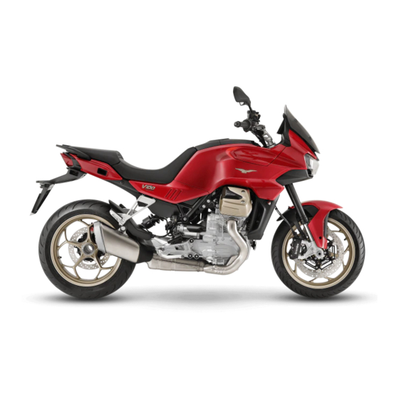
V100 Mandello - V100 Mandello S
Ed. 03_01/2023 Cod. 2Q000526 (IT-FR-DE-NL-ES-EN)
Advertisement
Table of Contents

Subscribe to Our Youtube Channel
Related Manuals for MOTO GUZZI V100 Mandello


Summary of Contents for MOTO GUZZI V100 Mandello
- Page 1 MOTO GUZZI WOULD LIKE TO THANK YOU for choosing one of its products. We have compiled this booklet to provide a comprehensive overview of your vehicle's quality features. Please read it carefully before riding the vehicle for the first time. It contains information, tips and precautions for using your vehicle. It also describes features, details and devices to assure you that you have made the right choice.
- Page 2 The instructions in this manual have been prepared to offer mainly a simple and clear guide to its use; it also describes routine maintenance procedures and regular checks that should be carried out on the vehicle at an authorised Moto Guzzi Dealer or Workshop, The booklet also contains instructions for simple repairs.
- Page 3 Personal safety Failure to completely observe these instructions will result in serious risk of personal injury. Safeguarding the environment Sections marked with this symbol indicate the correct use of the vehicle to prevent dam- aging the environment. Vehicle intactness The incomplete or non-observance of these regulations leads to the risk of serious damage to the vehicle and sometimes even the invalidity of the guarantee The symbols illustrated above are very important.
-
Page 5: Table Of Contents
INDEX GENERAL RULES............... USB Port................101 Carbon monoxide..............Identification................102 Fuel..................Adjusting the windscreen............103 Hot components..............USE....................105 Warning lights................ Checks..................106 Coolant.................. 10 Refuelling.................. 108 Used engine oil and gearbox oil..........11 Rear shock absorbers adjustment..........111 Brake fluid................11 Rear shock absorbers setting.......... - Page 6 Cooling fluid level..............150 Coolant check................ 151 Coolant top-up............... 151 Checking the brake oil level............152 Braking system fluid top up........... 153 Checking clutch fluid..............153 Topping up clutch fluid............153 Battery removal..............154 Checking the electrolyte level..........156 Charging the battery.............. 156 Long periods of inactivity............
-
Page 7: General Rules
V100 Mandello - V100 Mandello S Chap. 01 General rules... -
Page 8: Carbon Monoxide
Carbon monoxide CAUTION EXHAUST EMISSIONS CONTAIN CARBON MONOXIDE, A POISONOUS GAS WHICH CAN CAUSE LOSS OF CONSCIOUSNESS AND EVEN DEATH. CAUTION CARBON MONOXIDE IS ODOURLESS AND COLOURLESS, THEREFORE IT CANNOT BE DETECTED BY SMELL, SIGHT OR OTHER SENSES. DO NOT BREATHE IN EXHAUST FUMES UNDER ANY CIRCUMSTANCES. -
Page 9: Hot Components
KEEP OUT OF THE REACH OF CHILDREN. IF THE VEHICLE FALLS OR IS ON A STEEP INCLINE FUEL CAN LEAK. Hot components The engine and the exhaust system components get very hot and remain in this con- dition for a certain time interval after the engine has been switched off. Before handling these components, make sure that you are wearing insulating gloves or wait until the engine and the exhaust system have cooled down. -
Page 10: Coolant
PERFORM THE MOTOR OIL LEVEL CHECK. IF THE INSUFFICIENT MOTOR OIL PRESSURE LIGHT REMAINS DESPITE THE ABOVE PROCEDURE BEING PER- FORMED CORRECTLY, CONTACT AN AUTHORIZED Moto Guzzi Dealer TO HAVE THE SYSTEM CHECKED. Coolant Coolant contains ethylene glycol, which may be flammable in certain conditions. Eth- ylene glycol burns with an invisible flame which may still cause burns. -
Page 11: Used Engine Oil And Gearbox Oil
Used engine oil and gearbox oil CAUTION WHEN CARRYING OUT MAINTENANCE OPERATIONS, IT IS ADVISABLE TO WEAR PROTECTIVE IMPERMEABLE GLOVES. THE ENGINE OR GEARBOX OIL MAY CAUSE SERIOUS INJURIES TO THE SKIN IF HANDLED FOR PROLONGED PERIODS OF TIME AND ON A REGULAR BA- SIS. -
Page 12: Battery Hydrogen Gas And Electrolyte
Battery hydrogen gas and electrolyte CAUTION THE BATTERY ELECTROLYTE IS TOXIC, CORROSIVE AND, AS IT CONTAINS SULPHURIC ACID, MAY CAUSE BURNING IF IT COMES INTO CONTACT WITH THE SKIN. WHEN HANDLING BATTERY ELECTROLYTE, WEAR TIGHT-FITTING GLOVES AND PROTECTIVE APPAREL. IN THE EVENT OF SKIN CONTACT WITH THE ELECTROLYTIC FLUID, RINSE WELL WITH PLENTY OF CLEAN WATER. - Page 13 AT IDLE SPEED, AND IN EXTREMELY HOT CONDITIONS. IN ANY CASE, EVEN AFTER THE AUTOMATIC SHUT-DOWN, THE ENGINE CAN BE SWITCHED ON AGAIN IMMEDIATELY. • START IMMEDIATELY AFTER IGNITION, MAKING SURE TO RIDE A SHORT INITIAL DISTANCE AT LOW RPM. •...
- Page 14 Unless otherwise specified in this Use and Maintenance Manual, do not remove any mechanical or electrical component. CAUTION SOME CONNECTORS IN THE VEHICLE MAY BE ACCIDENTALLY SWAPPED AND MAY COMPROMISE NORMAL VEHICLE OPERATION IF INCORRECTLY IN- STALLED.
-
Page 15: Vehicle
V100 Mandello - V100 Mandello S Chap. 02 Vehicle... -
Page 16: Arrangement Of The Main Components
Arrangement of the main components (02_01, 02_02) 02_01... - Page 17 02_02 Key: 1. Headlamp 2. Adjustable windshield 3. Front left turn indicator 4. USB port 5. USB socket (where applicable) 6. Instrument panel 7. Clutch lever 8. Left rear-view mirror 9. Left light switch 10. Fuel tank cap 11. Fuel tank 12.
- Page 18 14. Main fuses 15. Rider saddle 16. Passenger saddle 17. Taillight 18. Seat lock 19. Licence plate lamp 20. Rear left turn indicator 21. Silencer 22. Rear brake calliper 23. Passenger left footrest 24. Side stand 25. Left rider footrest 26.
-
Page 19: Dashboard
52. Radiator 53. Radiator expansion tank 54. Rear brake disc 55. Right hand front brake disc Dashboard (02_03) 02_03 Key: 1. Audible warning device;... -
Page 20: Digital Instrument Panel
2. Turn indicator control; 3. Up button (MODE UP); 4. Set button (MODE SET); 5. Right button (MODE RIGHT); 6. Down button (MODE DOWN); 7. Low beam / high beam / flash high beam switch; 8. Cruise control selector; 9. Riding mode button; 10. - Page 21 The dashboard has an immobilizer system which prevents start-up in case the system does not identify a key which has been stored before. The vehicle is delivered to the customer with two pre-programmed keys. The dash- board accepts a maximum of four keys at the same time: contact an Official Moto Guzzi dealer to enable these keys or to disable a key that has been lost.
-
Page 22: Light Unit
Light unit (02_06) Key: 1. MI warning light, orange; 2. High beam indicator lamp, blue; 3. Cruise control indicator lamp, green; 4. ABS indicator light, orange; 5. Left turn indicator warning light, green; 6. Right turn indicator warning light, green; 7. - Page 23 (where available) If the GUZZI MIA ECU is present, pressing and holding the "MODE RIGHT" button accesses navigation mode. Pressing and holding the button changes the digital display mode from ROAD to NAVI, and then to MENU. Pressing and holding the MODE RIGHT button again scrolls through the "modes" available.
- Page 24 Key: 1) On-board computer log (TRIP LOG A / TRIP LOG B). (Where the Guzzi Mia control unit is present: telephone, music, media player. (Where the components are present): tyre pressure, heated handgrips, heated seat; 2) Riding mode active; 3) Clock (displayed in 24 or 12 hour mode, without the AM / PM indication); 4) Ice hazard icon (displayed at temperatures from -15 C°...
- Page 25 21) Downshift status (displayed where implemented); 22) Driving in reserve (only when the reserve indicator is on) (displayed in km or mi); 23) General warning icon; 24) Suspension failure icon (V100 Mandello S) Where the Guzzi Mia control unit is present: 25) GPS/Navigator (where active);...
- Page 26 ICE HAZARD WARNING At external temperatures between -15 °C (5 °F) and 3° C (37.4 °F), the ice hazard symbol appears on the display. 02_10 LOW BATTERY WARNING The lighting of the battery symbol indicates a problem in the battery charging system. 02_11 OVERTEMPERATURE WARNING When the coolant temperature is 115 °F (239 °C) or higher: the temperature icon turns...
- Page 27 CATES THAT THE FUEL LEVEL SENSOR IS DISCONNECTED. 02_13 IF THE FUEL SENSORS DO NOT WORK CORRECTLY, THE BARS MAY NOT BE DISPLAYED CORRECTLY. THEREFORE CONTACT AN Official Moto Guzzi Deal- NOTE THE INDICATED FUEL LEVEL MAY VARY AND NOT BE DISPLAYED ACCU- RATELY IF THE MOTORCYCLE IS INCLINED (E.G.
-
Page 28: Alarms
In the event of a fault, the Pop-up area of the digital display will turn red and a different message will be displayed depending on the cause. Take your vehicle to an Official Moto Guzzi Dealer as soon as possible. SERVICE ALARM... - Page 29 Take your vehicle to an Official Moto Guzzi Dealer as soon as possible. In these cases the ECU activates a safety procedure limiting vehicle performance in order to allow the rider to go to an Official Moto Guzzi Dealer at a reduced speed.
- Page 30 "ALARM OIL SENSOR" accompanied by the fixed general alarm icon, in the Pop-up area which will turn red. WARNING TAKE YOUR VEHICLE TO AN Official Moto Guzzi Dealer AS SOON AS POSSI- BLE. 02_20 MGCT disabled alarm The MGCT system disabling alarm is activated when there is a problem that can cause the system itself to be disabled.
- Page 31 GENERAL WARNING LIGHT, IN THE POP-UP AREA WHICH WILL TURN RED. 02_22 WARNING DRIVE CAREFULLY AND CONTACT AN Official Moto Guzzi Dealer AS SOON AS POSSIBLE. Electronic control unit disconnected alarm If a lack of connection of the E.C.U. is detected, the instrument panel will signal the anomaly by displaying the message "ALARM CAN ECU DISCONNECTED"...
- Page 32 If a lack of connection with the CAN line is detected, the display will show the alarm message "ALARM CAN BUS OFF" accompanied by the general warning icon the Pop- up area which will turn red. WARNING DRIVE CAREFULLY AND CONTACT AN Official Moto Guzzi Dealer AS SOON AS POSSIBLE. 02_24 Headlamp disconnected alarm "CAN HLU"...
- Page 33 Pop-up area will turn red. CAUTION IF THE ALARM MESSAGE DOES NOT DISAPPEAR WHEN RELEASING THE BRAKE LEVERS, STOP THE VEHICLE AND CONTACT AN Official Moto Guzzi 02_27 Dealer FOR DIAGNOSIS AND TROUBLESHOOTING OF THE BRAKE SYSTEM.
-
Page 34: Mapping Selection
Mapping selection (02_28, 02_29, 02_30, 02_31) The engine control unit has 4 different selectable "riding modes" for managing the electronic accelerator, displayed as follows in the upper central part of the digital dis- play: • SPORT • ROAD • TOUR •... - Page 35 Once the maximum level is reached, the setting will restart from the minimum inter- vention value. After setting the parameters as desired, press "MODE SET" briefly to exit the screen. 02_31 Press and hold "MODE SET" to restore the factory settings. NOTE The MGCS item is only present on V100 Mandello S.
-
Page 36: Control Buttons
Control buttons (02_32, 02_33, 02_34, 02_35, 02_36, 02_37, 02_38, 02_39, 02_40, 02_41, 02_42, 02_43, 02_44, 02_45, 02_46, 02_47, 02_48, 02_49, 02_50, 02_51, 02_52, 02_53, 02_54, 02_55) The control buttons on the left hand light switch may be used to navigate within the different screens of the system, view trip A / B log information and, if the vehicle is equipped with the GMP unit (Guzzi Multimedia Platform), also access phone infor- mation and music and media content. - Page 37 A number of different symbols (such as the examples (1) and (2) shown in the figure) may be displayed in the popup space. • Where shown as a solid shape (1), the symbol indicates that it is necessary to press and hold the relative control for the function described. •...
- Page 38 • DRIVING IN RESERVE (only when the reserve indicator is on). • MGCT (Moto Guzzi Traction Control) From any of the following view modes: TRIP ODOMETER, TRIP TIME, MAXIMUM SPEED, AVERAGE SPEED or AVERAGE FUEL CONSUMPTION, press and hold MODE SET to reset all the values logged in the currently active TRIP LOG.
- Page 39 D) Heated saddle information (displayed in ROAD / NAVI modes only) (where applicable) This menu provides information about the heated saddle, including the activation sta- tus and the heating intensity. For further details, see paragraph "Heated saddle control". 02_39 E) Tyre pressure information (displayed in ROAD and NAVI modes) (where pro- vided) Select this screen to view information relative to tyre pressure and temperature and possible alarms.
- Page 40 02_42 H) Media information (where provided) The vehicle is equipped with the "MOTO GUZZI MIA" accessory, which communicates with the smartphone via Bluetooth. Using the specific "MOTO GUZZI" application in- stalled on the smartphone, it is possible to exchange data with the vehicle and manage multimedia contents.
- Page 41 ROAD mode display with a pop-up confirming "PAIRING COMPLETED" or "PAIRING ABORTED" if the pairing does not take place correctly 02_45 The smartphone icon on the display indicates active communication. When reques- ted, allows phone book and notifications sharing. These enabling operations are necessary to display the caller's name on the display.
- Page 42 CONNECTION BETWEEN THE APPLICATION AND THE DIGITAL DISPLAY Search for the "Moto Guzzi" application in Play Store or App Store and install it. Reg- ister your account by following the instructions. Select "allow" for the position and notifications management requests.
- Page 43 The Bluetooth headset can be paired with the vehicle only via the "Moto Guzzi" ap- plication and it must be connected to the vehicle in order to correctly use the multimedia functions of the system.
- Page 44 NOTE PLEASE NOTE THAT TO CONNECT THE APP TO THE VEHICLE AGAIN, THE FOLLOWING WILL BE NECESSARY: • ON iOS, DELETE THE PREVIOUSLY INSTALLED APP AND REINSTALL • ON ANDROID, SIMPLY DELETE THE APPLICATION DATA FROM THE APP MANAGEMENT MENU (THIS WILL RETURN THE APPLICATION TO THE INITIAL CONDITION AND THE LOGIN AND FIRST CONNECTION TO THE VEHICLE MUST BE PERFORMED AGAIN).
- Page 45 The "Moto Guzzi" system manages the connection between the intercom and smart- phone upon activation by the user. FOR SAFETY REASONS, IT IS RECOMMENDED TO CARRY OUT THE ACTIVA- TION / DEACTIVATION PROCEDURES WITH THE VEHICLE AT A STANDSTILL. To activate the "INTERCOM" function, press and hold the MODE SET button from the "Media information"...
- Page 46 Pressing the MODE SET button briefly again deactivates the connection. The state "INTERCOM OFF" is now shown on the digital display. 02_52 To activate the "VOICE" function, which allows the user to access and use functions of their smartphone with voice commands from the headset (e.g. via Siri or Google Assistant), select the function with the MODE UP or MODE DOWN buttons and then press MODE SET briefly.
- Page 47 "Guzzi MIA" system via Bluetooth, as previously described; • install the "Moto Guzzi" app on your smartphone and access it (can be per- formed also from the instrument panel, without using the application); • pair a bluetooth headset with the "Guzzi MIA" system using the "Moto Guz- zi"...
- Page 48 Press and hold MODE SET to enable voice commands. Press MODE DOWN or MODE UP briefly to scroll through the log of all calls (missed calls, calls made, outgoing calls made with no reply). Select the required log entry and then press and hold MODE SET to call the relative contact.
- Page 49 "Guzzi MIA" system via Bluetooth, as previously described; • install the "Moto Guzzi" app on your smartphone and access it (can be per- formed also from the instrument panel, without using the application); • pair a bluetooth headset with the "Guzzi MIA" system using the "Moto Guz- zi"...
- Page 50 The following information appears on the digital display: • track playing; • playback paused; • playback interrupted. Use the MODE buttons to manage audio playback as shown in the table: MODE SELECTOR FUNCTIONS FOR MUSIC MANAGEMENT Play track PRESS MODE SET BRIEFLY Activate volume control (with call in PRESS AND HOLD MODE UP OR progress)
-
Page 51: Advanced Functions
Advanced functions (02_56, 02_57, 02_58, 02_59, 02_60, 02_61, 02_62, 02_63, 02_64, 02_65, 02_66, 02_67, 02_68, 02_69, 02_70, 02_71, 02_72, 02_73, 02_74, 02_75, 02_76, 02_77, 02_78, 02_79, 02_80, 02_81, 02_82, 02_83, 02_84, 02_85, 02_86, 02_87, 02_88, 02_89, 02_90, 02_91, 02_92, 02_93, 02_94, 02_95, 02_96, 02_97) With a long press of the MODE RIGHT button, from the ROAD screen, the display will pass to the NAVI screen (if the Guzzi MIA ECU is present) and then to the MENU screen. - Page 52 02_57...
- Page 53 1) Vehicle 2) Service 3) Instrument cluster 4) Riding mode 5) Multimedia - where required 6) MGCS (Moto Guzzi Suspension Control) - where required 02_58 1) Vehicle The "Vehicle" menu contains the following options: 1.1) Headlamp mode - where required 1.2) Shift light...
- Page 54 1.1) Headlamp mode - where required This function is used to set the operating mode of the lights. The use mode can be selected by shortly pressing the MODE RIGHT button. These modes will be displayed cyclically every time you press the button. Auto = Automatic Manual = Manual Emergency = Emergency;...
- Page 55 1.3) MGQS down - where required This function may be used to enable or disable the automatic matching system allow- ing downshifts without using the clutch. The activation status can be changed by briefly pressing the button. The function will be cyclically changed by further pressing the MODE RIGHT button.
- Page 56 02_65 02_66 To calibrate the MGCT system (Moto Guzzi Traction Control) ride along a flat straight road in second gear at a speed of 40 +/- 2 km/h (24.85 +/- 1.24 mph) for approximately 10 seconds, until the digital display shows a message "Calibration running Hold speed".
- Page 57 If calibration is completed successfully, the message "Calibration done - Key OFF (60s)" is displayed. NOTE WHEN THE TEXT "Calibration done - Key OFF (60s)" APPEARS ON THE DIS- PLAY, STOP THE VEHICLE AND TURN THE IGNITION TO KEY-OFF FOR AT LEAST 60 SECONDS TO COMPLETE CALIBRATION.
- Page 58 This function signals the presence of obstacles approaching from the rear of the ve- hicle, both right and left, by means of light signals on the display and on the relative rear-view mirror. 02_70 02_71 2) Service The "Service" menu contains the following options: 2.1) Change user code 2.2) Code recovery 2.3 Windshield...
- Page 59 2.6) HLU application (Firmware version) The functions available in the "Service" menu are described in the following para- graphs. Press MODE SET briefly to go back to the main MENU. 2.1) Change user code This function may be used to modify the existing code (you must be in possession of the code itself in order to do this).
- Page 60 seconds, the dashboard resets the user code to the default code (five zeros - 00000). Enter the new user code following the "CHANGE USER CODE " procedure. 2.3) Windshield This function also allows you to set the maximum speed at which the top fairing can be adjusted while riding, differentiating the setting for the two versions: •...
- Page 61 3.1) Backlight (Backlight) This function allows you to change the backlight of the digital display, from a minimum value of 1 to a maximum value of 10. The back light intensity can be increased with one point by briefly pressing on the MODE RIGHT button.
- Page 62 3.3) Units (Units) This menu allows you to change the settings for displaying the units and is divided as follows: 3.3.1) Speed (Speed) 3.3.2) Fuel consumption (Fuel consumption) 3.3.3) Temperature (Temperature) 3.3.4) Pressure (visible where applicable) 02_79 Press MODE SET briefly to go back to the "Dashboard" menu. 3.3.1) Speed (Speed) This function may be used to change the unit of measurement used for speed: •...
- Page 63 The measurement unit can be selected by shortly pressing the MODE RIGHT button. These units will be displayed cyclically every time you press the button. Press MODE SET briefly to go back to the "Dashboard" menu. 3.3.3) Temperature (Temperature) This function is used to change the measurement unit used for temperature: •...
- Page 64 Each "Riding mode" is composed of the following entries: MGCM (Moto Guzzi Engine Control) MGCT (Moto Guzzi Traction Control) MGCA (Moto Guzzi Aerodynamic Control) - where required MGCS (Moto Guzzi Suspension Control) - where required This function allows to edit the intervention level of each individual control system 02_82 associated with the Riding mode selected.
- Page 65 Press MODE SET briefly to go back to the main MENU. NOTE Intervention RANGE MGCM: 1 - 3 (1 = more aggressive intervention, 3 = softer intervention) MGCT: OFF - 4 (4 = maximum intervention) MGCA: you can select the speed at which the aerodynamic protections will open.
- Page 66 5.1) Devices status The "Devices status" menu allows to view the list of paired devices. Press MODE SET briefly to return to the "Multimedia" menu. 02_85 5.2) Devices pairing The "Devices pairing" menu allows to pair new devices. Press MODE SET briefly to return to the "Multimedia" menu. 02_86 5.3) Reset pairing (Delete pairing) The "Reset pairing"...
- Page 67 6) MGCS (Moto Guzzi Suspension Control) - where required The MGCS menu allows you to adjust the parameters of the OHLINS electronic sus- pension based on the preferences of the rider and the use conditions of the vehicle. The changes made will be effective on all Riding modes.
- Page 68 The "compression/extension" parameters can be modified from minimum 1 (HARD) to a maximum 31 (SOFT) (one unit corresponds to one click of a traditional suspen- sion) Briefly press on the MODE SET button to return to the "MGCS" menu. 6.2) Automatic dynamic / Automatic comfort The automatic modes actively adapt the suspension and relative adjustments based on the vehicle's behaviour in relation with the riding style.
- Page 69 GPS indications on the digital display. By means of pictograms, distance and travel time data, the desired destination can be reached. The navigation icon appears on the digital display after setting the destination address. Refer to the navigation guide by accessing the "MOTO GUZZI" application with your account. 02_91 Press and hold down MODE RIGHT to access the GPS navigation directions and information screen.
- Page 70 02_92 Navigation screen key: 1) Trip log (A / B) / Navigation information (If the Guzzi MIA ECU is present): telephone, music, media player. (Where the components are present): heated seat, heated handgrips; 2) Riding mode selected; 3) Clock (displayed in 24 or 12 hour format, without the AM / PM indication); 4) Ice hazard icon (displayed at temperatures from -15 °F (5 °C) to +3 °F (37.4 °C)) / Battery alert indicator (voltage between poles too low);...
- Page 71 21) Driving in reserve (only when the reserve indicator is on) (displayed in km or mi); 22) Indication regarding the speed limit applicable on the current road; 23) Suspension failure icon (V100 Mandello S); 24) Service icon; 25) Hand grip heating level indicator;...
- Page 72 • If navigating, the current destination is present. ELECTRONIC CONTROLS OF THE VEHICLE Moto Guzzi V100 is equipped with an advanced integrated electronic control system that helps improving the performance and the rider's safety. The system consists of: MGCM: Moto Guzzi Engine Control;...
- Page 73 The ABS with CORNERING is a device to avoid the wheels locking in case of emer- gency braking also when cornering, thus increasing vehicle stability when braking when compared with a traditional braking system. The CORNERING mode takes into account the motorcycle's lean angle, so as to maximise efficiency without endangering the rider.
- Page 74 - the ABS system is working. If the ABS disabled indication remains: NOTE IF THIS OCCURS, CONTACT AN OFFICIAL Moto Guzzi dealer. CAUTION If the ABS warning light flashes more frequently than that of the initial check, it means that there is a problem with the IMU inertial platform, which will not pro-...
- Page 75 In this case the MGCT traction control is deactivated, therefore riding the vehicle will be extremely dangerous. DRIVE WITH THE MAXIMUM CAUTION AND CON- TACT AN Official Moto Guzzi Dealer. NOTE IN THE EVENT OF A PROLONGED ROTATION OF THE REAR WHEEL WITH THE FRONT WHEEL LOCKED (BURNOUT, MOTORCYCLE PLACED ON THE CEN- TRAL STAND, ETC.) THE SYSTEM CAN BE AUTOMATICALLY DEACTIVATED...
- Page 76 SUCH BEHAVIOUR IS TO BE CONSIDERED NORMAL AND DOES NOT CREATE MALFUNCTIONS IN THE SYSTEM. IF THE DISTANCE OF THE FRONT SENSOR IS NOT INCLUDED IN THE INTER- VAL LISTED BELOW, CONTACT AN Official Moto Guzzi Dealer. Characteristic Distance between tone wheel and front sensor 0.5 - 1.50 mm (0.020 - 0.059 in)
- Page 77 - reactivate the system manually - ride the vehicle to a speed above 5 km/h (3.1 mph): the MGCT indicator light must turn off; - MGCT is working. If the MGCT disabled message remains: NOTE IF THIS OCCURS, CONTACT AN OFFICIAL Moto Guzzi dealer.
- Page 78 THE MGCT SYSTEM ACTS ON THE REAR WHEEL ON THE BASIS OF INFOR- MATION RECEIVED FROM TONE WHEELS INSTALLED ON BOTH WHEELS. IT IS IMPORTANT TO ALWAYS CHECK THAT THE TONE WHEEL IS IN PERFECT CONDITION, AND PERIODICALLY CHECK THAT THE DISTANCE FROM THE SENSOR IS CONSTANT OVER THE ENTIRE 360 DEGREES.
- Page 79 The system is active by default. However, if the system has been deactivated, in order to reactivate it, the user must access the specific screen using the selector button on the right hand handlebar control set Using the MODE navigation buttons, select level 1 if the level was set to 0. If the MGCT system is activated when the vehicle is stationary, the relative indicator light will flash until 3.1 mph (5 km/h) is reached.
- Page 80 The speed at which the deflectors are deployed can be adjusted by short presses of the MODE UP and MODE DOWN buttons. This setting is individually selectable for each of the riding modes. Moto Guzzi Suspension Control (where required) This vehicle is equipped with an ÖHLINS Smart EC 2.0. system.
- Page 81 The system is composed of front suspension, rear suspension and control unit (Sus- pension Control Unit). MGCS provides preset damping levels, optimized for various conditions, both for the front and rear suspensions. Through the control unit that receives signals from the various control units of the vehicle, the front and rear suspensions are constantly updated data on the driving conditions.
- Page 82 improves the filtering of the road bumps and the shock absorption; vice versa, an adjustment aimed at stability, increases the dampening of the movements. • Front compression: Energy absorption control when the front suspension is compressed. Therefore, the compression is adjusted when the front wheel is subjected to a load.
- Page 83 FACTORY SETTINGS TABLE A1 - Automatic A2 - Automatic M1 - Manual M2 - Manual Parameters dynamic comfort dynamic comfort Front firmness Front compression Front extension Rear firmness Rear compression Rear extension Brake support NOTE The adjustment ranges of the registers vary between "Automatic" and "Manual" and are: "Automatic": -5 (Soft) / +5 (Hard) "Manual": 1 (Hard) / 31 (Soft)
- Page 84 TRONIC SUSPENSION MANAGEMENT, THEY WILL NOT LOSE THEIR TRADI- TIONAL MECHANICAL FUNCTIONALITY. Moto Guzzi Quick Shift (where required) It is a system that allows go up and down the gears without having to use the clutch 'and without changing the position of the throttle grip.
- Page 85 - ride the vehicle to a speed above 5 km/h (3.1 mph): the warning light must turn off; - the MGQS is now functional. If the MGQS deactivated signal persists, contact an OFFICIAL MOTO GUZZI DEAL- FACTORY SETTINGS TABLE Riding mode...
-
Page 86: Ignition Switch
NOTE THE TABLE SHOWS THE MAXIMUM INDICATIONS ON THE SETTING LEVELS OF THE VARIOUS CONTROLS. EACH RIDER MAY PERSONALISE THE LEVELS TO THEIR OWN PREFERENCE IN ACCORDANCE WITH ABILITY, RIDING STYLE AND ROAD CONDITIONS. FOR MORE INFORMATION ON LEVEL SETTINGS, SEE THE RELATIVE PARA- GRAPHS FOR EACH INDIVIDUAL FUNCTION. -
Page 87: Locking The Steering Wheel
NOTE THE KEY IS USED IN THE IGNITION/STEERING LOCK SWITCH, THE KEYHOLE FOR THE FUEL TANK CAP, AND FOR THE SADDLE COMPARTMENT. NOTE THE LIGHTS COME ON AUTOMATICALLY AFTER THE ENGINE STARTS. NOTE KEEP THE SPARE KEY IN DIFFERENT PLACE, NOT WITH THE VEHICLE. LOCK (1): The steering is locked. -
Page 88: Horn Button
To lock the steering: • Turn the handlebar fully to the left. • Turn the key to «OFF». • Push in the key and turn it anticlockwise (to the left), steer the handlebar slowly until the key is set to «LOCK». •... -
Page 89: Switch Direction Indicators
Switch direction indicators (02_101) Move the switch to the left to indicate a left turn; move the switch to the right to indicate a right turn. Pressing the switch deactivates the turn indicator. 02_101 The turn indicators have a self-cancelling function that implements the following logic. With the vehicle at standstill (speed = zero), the turn indicators continue flashing in- definitely. -
Page 90: High/Low Beam Selector
High/low beam selector (02_102) In DRL ON mode: • the DRL lights only are lit when the selector is left in the centre position (2). • pressing the selector into position (1) switches on the high beam headlight • press the selector into position (3) to flash the high beam headlamp to signal danger or an emergency. -
Page 91: Daytime/Night Lights Switch
Daytime/night lights switch (02_104, 02_105) This button allows to select the use mode of the daytime running lights (DRL), night lights (low / high beams) and the activation of the fog lights (where provided). • Press the button briefly to cycle through the modes available (daytime/night- time lights). -
Page 92: Heated Handgrip Control
WARNING Flashing of the fog lights icon on the digital display indicates a problem with the front light cluster. Contact an OFFICIAL MOTO GUZZI DEALER as soon as possible. Heated handgrip control (02_106, 02_107) (if applicable) The activation, deactivation and heat level of the heated hand grips is performed with the control button. -
Page 93: Start-Up Button
Heated saddle control (where provided) The heated saddle is switched on, off and the heat level is set using the control buttons. The page dedicated to setting the heated saddle can be viewed by scrolling through the pages in the space dedicated to the trip log. By briefly pressing the MODE UP button it is possible to activate the heating and subsequently with further presses to increase the heat intensity level. -
Page 94: Engine Stop Switch
Engine stop switch (02_109) CAUTION DO NOT OPERATE THE ENGINE STOP SWITCH WHILE RIDING THE VEHICLE. It acts as a safety or emergency switch. Press and hold the ignition switch in the "KEY ON" position to start the engine; press the switch to set it to "KEY OFF"... - Page 95 Cruise control is an electronic system that keeps the vehicle at a constant speed se- lected by the rider. Push and hold (more than 1 second) the cruise control selector to the left switch the system on (OFF -> ON). The relative indicator on the dashboard instrument panel flashes to confirm that the system is on.
- Page 96 rarily by up to 30 km / h (18.64 mph) for the third, fourth and fifth gear and 40 km / h (24.85 mph) for the sixth gear with respect to the selected speed without turning off the system (e.g. passing). If the increase in speed exceeds 30 km/h (18.64 mph) for the third, fourth and fifth gear and 40 km/h (24.85 mph) for the sixth gear, it will cause a system deactivation (change from SET to ON, flashing light).
-
Page 97: Immobilizer System Operation
CAUTION WHEN ENTERING THE ADJUSTMENT MODE OF THE CRUISE CONTROL, THE QUICK SHIFT SYSTEM IS DISABLED. Immobilizer system operation (02_114, 02_115, 02_116) For enhanced theft protection, the vehicle is equipped with an electronic immobilizer system that is activated automatically when the ignition key is removed. Keep the second key in a safe place since it is not possible to make a copy if it gets lost. - Page 98 Once the code has been correctly entered, the identified error will be displayed on the screen. It is then possible to start the motorcycle so you can go immediately to an Authorised Moto Guzzi Dealer. CAUTION PRESSING OR MOVING ANY CONTROL ON THE LEFT SWITCH CLUSTER, IT IS POSSIBLE TO REMOVE THE ERROR NOTIFICATION SCREEN, BUT THE SCREEN WILL BE VISIBLE AGAIN AFTER ABOUT 10 SECONDS.
-
Page 99: Opening The Saddle
Opening the saddle (02_117, 02_118, 02_119, 02_120, 02_121) • Rest the vehicle on its stand. • Insert the key in the saddle lock located on the left-hand side fairing. • Turn the key clockwise to release the passenger saddle from the lock. 02_117 •... - Page 100 Refitting the saddles: • Move the rider saddle rider in its position, taking care to insert the central fastener and the two front fasteners in the relative seats. 02_120 • Insert the rear fastener of the passenger saddle in its support on the vehicle. •...
-
Page 101: Usb Port
USB Port (02_122, 02_123) The vehicle is equipped with a USB port, located in the storage compartment under the passenger saddle. To use it, remove the protection cap from the port. To prevent damage to the port, put the protective cap whenever the port is not in use. IF A USB DEVICE IS CONNECTED, ENSURE THE CORRECT POSITIONING OF 02_122 THE CABLE TO AVOID THAT IT WILL BE SMASHED. -
Page 102: Identification
PORT Output voltage: (5.00+/-0.25) dc Charge current 1A Max Identification (02_124, 02_125) Write down the chassis and engine number in the specific space in this booklet. The chassis number is handy when purchasing spare parts. CAUTION THE MODIFICATION OF THE IDENTIFICATION CODES IS A SERIOUS PUNISH- ABLE CRIME. -
Page 103: Adjusting The Windscreen
ENGINE NUMBER The engine number is stamped on the left side of the crankcase, under the cylinder. Engine No..... 02_125 Adjusting the windscreen (02_126) The windscreen height can be adjusted electronically by selecting "WINDSCREEN REGULATION" using the "MODE SET" button on the left-hand switch. The height can then be adjusted using the MODE UP and MODE DOWN buttons on the left-hand switch. -
Page 105: Use
V100 Mandello - V100 Mandello S Chap. 03... -
Page 106: Checks
VEHICLE, FOR CORRECT AND SAFE OPERATION. FAILURE TO DO SO MAY CAUSE SEVERE PERSONAL INJURY OR VEHICLE DAMAGE. DO NOT HESI- TATE TO CONTACT AN Official Moto Guzzi Dealer IF YOU DO NOT UNDER- STAND HOW SOME CONTROLS WORK OR IF MALFUNCTIONING IS DETECTED OR SUSPECTED. - Page 107 Throttle grip Check that the rotation is smooth in both directions and that there is no jamming. Engine oil Check and/or top-up as required. Wheels/ tyres Check that tyres are in good conditions. Check inflation pressure, tyre wear and potential damage.
-
Page 108: Refuelling
Check the circuit for leaks or obstructions. Check that the tank cap closes correctly. Engine stop switch (ON - OFF) Check function. Lights, warning lights, horn and Check function of horn and lights. electrical devices Tone wheel Check the front tone wheel for cleanliness and damage. - Page 109 17 l (3.74 UK gal; 4.49 US gal) Fuel tank reserve capacity 3.5 +/- 0.5 l (0.77 +/- 0.11 UK gal; 0.92 +/- 0.13 US gal) NOTE NEVER COMPLETELY TOP-UP THE RESERVOIR; THE MAXIMUM FUEL LEVEL MUST REMAIN BELOW THE LOWER EDGE OF THE SUMP (SEE FIGURE). The EN16942 European standard requires the identification of the compatibility of the vehicles with the fuel type by means of a graphic symbol for consumer information.
- Page 110 CAUTION DO NOT ADD ADDITIVES OR ANY OTHER SUBSTANCES TO THE FUEL. WHEN USING A FUNNEL, ENSURE THAT IT IS PERFECTLY CLEAN. DURING REFUELLING AVOID FUEL LEAKAGES, WHICH MAY CAUSE DAMAGE TO THINGS OR PERSONS AND FIRE HAZARD. DURING REFUELLING, AVOID THE USE OF ELECTRIC DEVICES AND/OR MO- BILE PHONES, BECAUSE FUEL VAPOURS MAY CAUSE DAMAGE TO OBJECTS AND/OR PERSONAL INJURIES.
-
Page 111: Rear Shock Absorbers Adjustment
LIMIT STOP IN BOTH DIRECTIONS, IN ORDER TO PREVENT ANY DAMAGE. 03_05 On the upper part of the shock absorber, only for "V100 Mandello", there is an adjuster ( 2) to adjust the rebound hydraulic braking. Instead, the shock absorber settings on "V100 Mandello S"... - Page 112 CREASE THE REBOUND DAMPING ACCORDINGLY TO AVOID SUDDEN JERKS WHEN RIDING. CAUTION ALWAYS OBSERVE THE RECOMMENDED ADJUSTMENT RANGE. FOR THE CORRECT SETTING PARAMETERS, READ THE PARAGRAPH "SET- TING THE REAR SHOCK ABSORBERS" CAREFULLY. IF NECESSARY, CONTACT AN Official Moto Guzzi Dealer.
-
Page 113: Rear Shock Absorbers Setting
Rear shock absorbers setting (03_07, 03_08, 03_09) V 100 MANDELLO Spring pre-load adjustment To adjust the spring pre-load, turn the adjuster knob (1) clockwise to increase the pre- load or counterclockwise to decrease it. CAUTION DO NOT FORCE THE ROTATION OF THE ADJUSTMENT SCREW BEYOND THE LIMIT STOP IN BOTH DIRECTIONS, IN ORDER TO PREVENT ANY DAMAGE. - Page 114 RECOMMENDED SETTING V100 MANDELLO RIDER + BAGS AND RIDER + PASSENGER TYPE OF ADJUSTMENT RIDER ONLY TOP CASE OR RIDER + BAGS AND TOP + PASSENGER CASE PRE-LOAD (KNOB) - FROM COMPLETELY OPEN (**) 1 click 22 clicks 26 clicks...
- Page 115 RETURN EACH MODE TO THE FACTORY SETTINGS, AS EXPLAINED IN THE "ADVANCED FUNCTIONS" PARAGRAPH. IF YOU WANT TO CHANGE THE FACTORY SETTINGS, TEST THE VEHICLE RE- PEATEDLY UNTIL THE OPTIMUM ADJUSTMENT IS OBTAINED. IF NECESSARY, CONTACT AN Official Moto Guzzi Dealer.
-
Page 116: Front Fork Adjustment
CAUTION 03_10 TO HAVE THE FRONT FORK OIL AND OIL SEALS REPLACED, CONTACT AN Official Moto Guzzi Dealer. V 100 MANDELLO The front suspension consists of a hydraulic fork connected to the headstock by means of two plates. - Page 117 CAUTION FOR THE CORRECT SETTING PARAMETERS, READ THE PARAGRAPH "SET- TING THE FRONT FORK" CAREFULLY. IF NECESSARY, CONTACT AN Official Moto Guzzi Dealer. V 100 MANDELLO S • The spring pre-load is adjusted by the manufacturer to suit any riding type;...
- Page 118 • To adjust the spring pre-load, it is necessary to disconnect the connector (1) from the stem plug, so as not to twist the wiring harness during the adjustment operations. 03_13 TO AVOID DAMAGING THE CONNECTOR, PRESS THE TAB (2) ON THE INDI- CATED POINT AND THEN CAREFULLY REMOVE THE CONNECTOR.
-
Page 119: Front Fork Setting
BY INCREASING THE SPRING PRE-LOAD, THE CONTROL PARAMETERS OF THE FRONT FORK MUST BE ADJUSTED (BY INCREASING THEIR VALUES) TO AVOID UNEXPECTED JOLTS WHILE DRIVING. • The "V 100 Mandello S" fork adjustments are performed electronically; these settings can be adjusted via the instrument panel. For more information, refer to "ADVANCED FUNCTIONS"... - Page 120 1 notch (5 mm - 0.20 in) 1 notch (5 mm - 0.20 in) YOKE (EXCLUDING COVER) (*) - Clockwise (**) - Anticlockwise (***) - this type of adjustment may only be made by an Authorised Moto Guzzi Deal- V 100 MANDELLO S...
- Page 121 • Stanchion protrusion (A) (***): 1 notch (4 mm - 0.16 in) (***) - this type of adjustment may only be made by an Authorised Moto Guzzi Deal- 03_19 ALL MODES CAN BE EDITED BY THE USER AND IT IS ALWAYS POSSIBLE TO RETURN EACH MODE TO THE FACTORY SETTINGS, AS EXPLAINED IN THE "ADVANCED FUNCTIONS"...
-
Page 122: Adjusting The Front Brake Lever
CAUTION IF THE FRONT BRAKE LEVER MUST BE REMOVED, CHECKED AND CHANGED 03_20 BY AN Official Moto Guzzi Dealership Rear brake pedal adjustment (03_21) The control levers are positioned ergonomically when the vehicle is being assembled. if necessary, it is possible to customise the position of the levers. -
Page 123: Clutch Lever Adjustment
• Turning the adjuster clockwise moves the lever (1) away from the handle (2). CAUTION CONTACT AN Official Moto Guzzi dealer TO REMOVE AND REPLACE THE 03_22 CLUTCH LEVER IN THE EVENT FAULTS AND/OR MALFUNCTIONS IN THE CLUTCH CONTROL,... -
Page 124: Starting Up The Engine
TO PREVENT THE RISK OF INJURY TO YOURSELF OR OTHERS AND/OR DAM- AGE TO THE VEHICLE, TAKE THE YOUR MOTORCYCLE TO AN AUTHORISED Moto Guzzi DEALER AT THE SPECIFIED MILEAGE INTERVALS TO HAVE THE CHECKS LISTED IN THE "SCHEDULED MAINTENANCE TABLE" CARRIED OUT. - Page 125 CAUTION WITH THE SIDE STAND LOWERED, THE ENGINE MAY ONLY BE STARTED WITH THE GEARBOX IN NEUTRAL. IF YOU ATTEMPT TO ENGAGE THE GEAR, THE ENGINE WILL STOP. WITH THE SIDE STAND RETRACTED, THE ENGINE MAY BE STARTED WITH THE GEARBOX IN NEUTRAL OR WITH THE GEAR ENGAGED AND THE CLUTCH LEVER OPERATED.
- Page 126 TON ASSUMES THE RIDING MODE CHANGE FUNCTION. IF THE GENERAL WARNING INDICATOR LIGHT ON THE DASHBOARD COMES ON, IT MEANS THAT THE CONTROL UNIT HAS ENCOUNTERED A FAULT, 03_25 THEREFORE IT IS NECESSARY TO CONTACT AN Authorised Moto Guzzi Deal-...
-
Page 127: Moving Off / Riding
DO NOT SET OFF SUDDENLY WHEN THE ENGINE IS COLD. RIDE AT LOW SPEED FOR SEVERAL KILOMETRES. THIS WILL ALLOW THE ENGINE TO WARM UP AND REDUCE POLLUTING EMISSIONS AND FUEL CONSUMPTION. Moving off / riding (03_26, 03_27, 03_28) CAUTION THE ECU INSTALLED ON THIS MOTORCYCLE COMPENSATES FOR IN- CREASED ELECTRIC POWER CONSUMPTION BY TEMPORARILY RAISING THE IDLE SPEED;... - Page 128 CAUTION PASSENGERS MUST BE SUITABLY INSTRUCTED ON HOW TO BEHAVE TO PREVENT DANGEROUS SITUATIONS WHEN RIDING. BEFORE SETTING OFF, MAKE SURE THE STAND HAS BEEN COMPLETELY RETRACTED TO ITS POSITION. To start: • Turn on the engine. • Adjust the inclination of the rear-view mirrors to ensure proper visibility. CAUTION WITH THE VEHICLE AT STANDSTILL, PRACTICE USING THE REAR-VIEW MIR- RORS.
- Page 129 • Slowly release the clutch lever and accelerate by slightly turning the throttle grip at the same time (Pos. B). The vehicle starts moving forward. • Ride at moderate speed for the first kilometres/miles to allow the engine to warm up. •...
- Page 130 • Release the throttle grip (Pos. A). • If necessary, pull the brake levers gently and reduce speed. • Operate the clutch lever and lower the gearshift lever (1) to engage a lower gear. • Release the brake levers when it is operated. •...
-
Page 131: Stopping The Engine
Stopping the engine (03_29) • Release the throttle grip (Pos. A), brake gradually and simultaneously down- shift to slow down. Once the speed is reduced, before stopping the vehicle: • Operate the clutch lever (1) so that engine does not shut off. When the vehicle is at standstill: •... -
Page 132: Catalytic Silencer
NOT A HAZARD TO PERSONS OR CHILDREN. DO NOT LEAVE YOUR VEHICLE UNATTENDED WITH THE ENGINE ON OR THE KEY IN THE IGNITION SWITCH. CAUTION IF THE VEHICLE FALLS OR IS ON A STEEP INCLINE FUEL CAN LEAK. FUEL USED TO DRIVE INTERNAL COMBUSTION ENGINES IS HIGHLY FLAM- MABLE AND CAN BECOME EXPLOSIVE UNDER CERTAIN CONDITIONS. -
Page 133: Stand
If the noise produced by the exhaust system increases, get immediately in touch with the Dealer or with a Moto Guzzi authorised repair shop. NOTE DO NOT TAMPER WITH THE EXHAUST SYSTEM. -
Page 134: Suggestion To Prevent Theft
THE AREA AND CHECK THE LIGHT ON THE DASHBOARD WITH THE STAND DOWN. IF WITH THE STAND OPEN, THE SIDE STAND WARNING LIGHT REMAINS OFF DESPITE CLEANING, PLEASE CONTACT an Authorised Moto Guzzi Dealer. 03_31 Suggestion to prevent theft CAUTION WHEN USING A DISC LOCKING DEVICE, PAY UTMOST ATTENTION TO RE- MOVE IT BEFORE RIDING. -
Page 135: Safe Driving
NEVER leave the ignition key in the lock and always use the steering lock. Park the vehicle in a safe place such as a garage or a place with guards. Whenever possible, use an additional anti-theft device. Make sure all vehicle documents are in order and the road tax paid. - Page 136 6. If the motorcycle is used on roads covered with sand, mud, snow mixed with salt etc., clean the brake discs frequently with a mild detergent to prevent abrasive parti- cles from accumulating in the disc ventilation holes and causing accelerated brake pad wear.
-
Page 137: Basic Safety Rules
Basic safety rules (03_32, 03_33, 03_34, 03_35, 03_36) The following recommendations should receive your maximum attention, because they are provided to increase your safety, and decrease damage to people, things and vehicles, in the case of a fall of the rider or passenger from the vehicle and/or from the fall or overturning of the vehicle. - Page 138 In any case, the passenger should mount and dismount the vehicle using caution to avoid causing the vehicle or the rider to lose balance. CAUTION THE RIDER TO INSTRUCT THE PASSENGER ABOUT THE PROPER WAY TO MOUNT AND DISMOUNT FROM THE VEHICLE. THE VEHICLE INCLUDES PASSENGER FOOTRESTS WHICH SHOULD BE USED DURING MOUNTING AND DISMOUNTING.
- Page 139 THE CASES SHALL NOT BE USED AS A SUPPORT AND THE HANDLES SHALL NOT BE USED AS ANCHORAGE FOR THE PASSENGER. MOUNTING • Grip the handlebar properly and mount the vehicle without placing your weight upon the side stand. CAUTION IN THE CASE THAT YOU ARE NOT ABLE TO REST BOTH FEET ON THE GROUND, PUT THE RIGHT FOOT ON THE GROUND, (IN THE CASE OF A LOSS OF BALANCE THE LEFT SIDE IS "PROTECTED"...
- Page 140 • Have the passenger open the two passenger foot pegs. • Show the passenger how to mount the vehicle. • Use your left foot to push on the side stand and make it fully return to its position. DISMOUNTING • Select an appropriate parking spot.
- Page 141 DO NOT PLACE YOUR WEIGHT UPON THE SIDE STAND. • Lean the motorcycle until the stand touches the ground. • Correctly grip the handlebar, and dismount from the vehicle. • Turn the handlebar completely to the left. • Place the passenger footrest in its place. CAUTION MAKE SURE THE VEHICLE IS STABLE.
-
Page 143: Maintenance
V100 Mandello - V100 Mandello S Chap. 04 Maintenance... -
Page 144: Foreword
In general terms, scheduled maintenance can be carried out by the owner; however, some operations may require specific tools and technical training. For periodic main- tenance, servicing or technical advice, contact an Official Moto Guzzi Dealer for prompt and accurate service. - Page 145 ICAL LOCATIONS WITH ADVERSE CLIMATIC CONDITIONS, USE ON UNEVEN GROUND OR SEVERE INDIVIDUAL USE. THE OIL LEVEL MUST BE CHECKED WHEN THE ENGINE IS WARM. CAUTION DO NOT LET THE ENGINE IDLE WITH THE VEHICLE AT A STANDSTILL TO WARM UP THE ENGINE AND OBTAIN THE OPERATING TEMPERATURE OF ENGINE OIL.
-
Page 146: Engine Oil Top-Up
04_02 Engine oil top-up CAUTION IF IT IS NECESSARY TO TOP UP THE ENGINE OIL LEVEL, CONTACT AN official Moto Guzzi dealer. Engine oil change CAUTION THE ENGINE OIL MUST BE CHECKED AND CHANGED BY AN Official Moto Guzzi Dealership... -
Page 147: Bevel Gear Pair Oil Level
Bevel gear pair oil level CAUTION TO TOP-UP OR CHANGE THE OIL IN THE CARDAN SHAFT TRANSMISSION UNIT, CONTACT AN Official Moto Guzzi Dealer. Tyres (04_03, 04_04) This vehicle is fitted with tubeless tyres (without inner tubes). CAUTION CHECK TYRE INFLATION PRESSURE REGULARLY AT AMBIENT TEMPERA- TURE. - Page 148 CARRY OUT A VISUAL INSPECTION FOR TYRE WEAR AND TEAR, REPLACE TYRES WHEN WORN. WHEN TYRES ARE OLD, THE MATERIAL MAY HARDEN AND NOT PROVIDE ADEQUATE ROAD HOLDING, EVEN IF TYRES ARE STILL WITHIN THE WEAR LIMIT. REPLACE TYRES IF THIS OCCURS. REPLACE THE TYRE IF IT IS WORN OR IF THERE IS A PUNCTURE LARGER THAN 5 mm (0.197 in) IN THE TREAD AREA.
-
Page 149: Spark Plug Dismantlement
The positioning of the levers for the removal of the tyre must be at a distance of at least 10 cm (3.93 in) from the inflation valve. Spark plug dismantlement CAUTION FOR REMOVAL, CHECK, AND REPLACEMENT OF THE SPARK PLUGS CON- TACT AN OFFICIAL Moto Guzzi Dealer. -
Page 150: Removing The Air Filter
Removing the air filter CAUTION TO REMOVE, CHECK AND REPLACE THE AIR FILTER, CONTACT AN Official Moto Guzzi Dealer. Cooling fluid level Do not use the vehicle if the coolant level is below the minimum marking. CAUTION COOLANT IS TOXIC IF INGESTED; CONTACT WITH YOUR EYES OR SKIN MAY CAUSE IRRITATION. -
Page 151: Coolant Check
(1) "MAX" and (2) "MIN" ref- erence marks. WARNING CARRY OUT THE CHECK AND TOP UP THE REFRIGERANT LIQUID WITH THE ENGINE SWITCHED OFF AND COLD. 04_06 TO REPLACE THE COOLANT, CONTACT AN Official Moto Guzzi Dealer... -
Page 152: Checking The Brake Oil Level
Check the brake pads and discs for wear. If the brake pads and/or brake discs do not have to be replaced, have the braking system checked at an Official Moto Guzzi Dealership. CAUTION FLUID LEVEL DECREASES GRADUALLY AS BRAKE PADS WEAR DOWN. -
Page 153: Braking System Fluid Top Up
(2): MAX = maximum level If the fluid does not reach the "MIN" reference, have the clutch system checked by an 04_09 Official Moto Guzzi dealer. Topping up clutch fluid CAUTION FOR THE TOP-UP OF THE CLUTCH FLUID, CONTACT AN Official Moto Guzzi Dealer... -
Page 154: Battery Removal
Battery removal (04_10, 04_11, 04_12, 04_13) • Make sure the ignition switch is set to "KEY OFF"; • Remove the rider saddle; • Disconnect the connector (1) of the OBD2 socket; • Remove the cable (2) of the GMP provision, moving it forward to release it from its support;... - Page 155 • Unscrew and remove the screw (4) from the negative terminal (-). • Move the negative lead (5) aside. • Move the protection cap (6), unscrew and remove the screw (7) from the positive terminal (+). • Move the positive lead (8) aside. •...
-
Page 156: Checking The Electrolyte Level
Checking the electrolyte level WARNING THIS VEHICLE IS FITTED WITH A MAINTENANCE-FREE BATTERY AND DOES NOT NEED ANY INTERVENTION, EXCEPT FOR SPORADIC CHECKS AND RE- CHARGE. Charging the battery • Remove the battery. • Get an adequate battery charger. • Set the battery charger for the recharge type indicated. -
Page 157: Long Periods Of Inactivity
- Time: 1 hours Long periods of inactivity If the vehicle is inactive longer than fifteen days, it is necessary to recharge the battery to avoid sulphation. • Remove the battery and put it away in a cool and dry place. In winter or when the vehicle is out of use for prolonged periods, check charge level frequently (about once a month) to prevent deterioration. - Page 158 NOTE A FUSE THAT BLOWS FREQUENTLY MAY INDICATE A SHORT CIRCUIT OR OVERLOAD. IF THIS OCCURS, CONTACT AN Official Guzzi Dealer. To check: • Set the ignition switch to 'OFF' to avoid an accidental short circuit; • Remove the passenger saddle; •...
- Page 159 They are located under the tank, in front of the E.C.U. If there is a problem with the main fuses, DO NOT replace them, but take your vehicle to an Official Moto Guzzi dealer. 04_16 AUXILIARY FUSES (1)
- Page 160 rear radar key-on positive (if provided), main ignition relay D) 7.5A fuse Key-on power for smart EC key-on positive (if provided) E) 7.5A fuse GMP key-on positive (if provided), OBD key-on positive, anti-theft system positive F) 7.5A fuse Headlamp key-on positive G) 3A fuse USB 1 and 2 key-on positive (2 if provided)
-
Page 161: Front Light Group
O) 5A fuse Instrument panel power supply (turn indicators) P) 20A fuse ABS power feed Q) Spare fuses They are located on the tail fairing, under the passenger saddle 04_17 Front light group (04_18, 04_19, 04_20) The headlamp unit uses LED light sources only, and consists of the following modules: •... - Page 162 NOTE WHEN THE REAR WHEEL EXCEEDS THE SPEED OF 1 km/h (0.62 mph) (EVEN WITH THE ENGINE OFF, AND THE KEY SET TO ON), THE HEADLIGHTS WILL TURN ON AND WILL REMAIN ON FOR 30 SECONDS (FROM THE TIME IN WHICH THE REAR WHEEL STOPS MOVING).
-
Page 163: Headlight Adjustment
CAUTION TO REMOVE, CHECK AND REPLACE THE FRONT LIGHT ASSEMBLY LAMPS, CONTACT AN Authorised Moto Guzzi Dealership Headlight adjustment (04_21, 04_22, 04_23) NOTE IN COMPLIANCE WITH LOCAL LEGAL REQUIREMENTS, SPECIFIC PROCE- DURES MUST BE FOLLOWED WHEN CHECKING LIGHT BEAM ADJUSTMENT. -
Page 164: Front Direction Indicators
Turning the screw clockwise lowers the headlamp, and counterclockwise raises the headlamp. 04_23 Front direction indicators NOTE TO REMOVE, CHECK AND REPLACE THE FRONT TURN INDICATORS, PLEASE CONTACT AN Authorised Moto Guzzi Dealership... -
Page 165: Rear Optical Unit
Rear turn indicators NOTE FOR DISASSEMBLY, VERIFICATION AND REPLACEMENT OF REAR INDICA- TORS PLEASE CONTACT AN Official Moto Guzzi Dealership Rear-view mirrors (04_24, 04_25) DO NOT RIDE WITH REAR-VIEW MIRRORS INCORRECTLY SET. ALWAYS CHECK THAT THE MIRRORS ARE ADJUSTED CORRECTLY BEFORE... - Page 166 Removing the rear-view mirrors: • Rest the vehicle on its stand. • Lift the rubber protection (1). • Loosen the fastening nut (2) by ensuring that the threaded clamp (3) cannot rotate. • Slide up and remove the complete rear-view mirror unit (4). Repeat the procedure to remove the other rear-view mirror, if necessary.
-
Page 167: Front And Rear Disc Brake
REPLACE DIRTY PADS AND CLEAN AGAIN THE DIRTY DISC USING A TOP QUALITY DEGREASING PRODUCT. CAUTION TAKE YOUR VEHICLE TO AN Official Moto Guzzi Dealer TO HAVE THE FRONT WHEEL REMOVED. CAUTION CHECK BRAKE PADS FOR WEAR MAINLY BEFORE EACH RIDE. -
Page 168: Periods Of Inactivity
If the friction material thickness (even of one front or rear pad) is reduced to a value of about 1.5 mm (0.059 in) (or even if one of the wear indicators is not very visible), contact an Official Moto Guzzi Dealer to replace all the brake callipers. 04_28... - Page 169 • Store the motorcycle in a cool, dry place, not exposed to sun rays and with minimum temperature variations. • Wrap and tie a plastic bag around the exhaust pipe opening to keep moisture out. CAUTION PLACE THE VEHICLE ON SUITABLE SUPPORTS TO KEEP THE TYRES OFF THE GROUND.
-
Page 170: Cleaning The Vehicle
Cleaning the vehicle (04_30, 04_31, 04_32) Moto Guzzi recommends using quality products for cleaning the vehicle. The use of unsuitable products can damage vehicle components. For cleaning do not use sol- vents such as "nitro thinner", "cold cleaning agents", or similar fuels, or cleaning products that contain alcohol. - Page 171 BODYWORK To keep the motorcycle bright, wash it regularly, especially if used in areas with high levels of pollution or mud. Aggressive stains from tree resins, gasoline, oil, brake fluid or bird excrement in general. must be removed immediately, otherwise permanent stains on the paint can appear. After washing is easy to identify marks and residual stains, remove these from the bodywork using a soft cloth, of a non-abrasive polish brand.
- Page 172 POLISHING PASTE. THE VEHICLE SHOULD NEVER BE WASHED IN DIRECT SUNLIGHT, ESPECIALLY DURING SUMMER, OR WITH THE BODYWORK STILL HOT AS THE CAR SHAMPOO CAN DAMAGE THE PAINTWORK IF IT DRIES BE- FORE BEING RINSED OFF. CAUTION WARNING AFTER HEAVY RAIN, WASHING OR IN CASE OF RAPID TEMPERATURE CHANGES, THE LENSES OF THE FRONT LIGHT ASSEMBLY MAY BECOME FOGGY.
- Page 173 THE USE OF SILICONE SPRAY TO CLEAN THE RUBBER SEALS MAY CAUSE DAMAGE. DO NOT USE OTHER PRODUCTS CONTAINING SILICON FOR CLEANING THE MOTORCYCLE Clean the motorcycle frequently if exposed to adverse conditions, such as: • Air pollution (cities and industrial areas). •...
- Page 174 CAUTION AFTER CLEANING YOUR MOTORCYCLE, BRAKING EFFICIENCY MAY BE TEM- PORARILY AFFECTED DUE TO THE PRESENCE OF WATER ON THE FRICTION SURFACES OF THE BRAKING CIRCUIT. ALLOW LONGER BRAKING DISTAN- CES TO PREVENT ACCIDENTS. BRAKE REPEATEDLY TO RESTORE NORMAL OPERATION. CARRY OUT THE PRE-RIDE CHECKS. To remove dirt and mud accumulated on painted surfaces, wet the soiled areas thor- oughly with a low-pressure water jet, then remove dirt and mud with a soft car body sponge soaked abundantly in a solution of car body shampoo in water (2 - 4% sham-...
-
Page 175: Transport
CAUTION DO NOT USE SOLVENTS OR PETROL BY-PRODUCTS (ACETONE, TRICHLORO- ETHYLENE, TURPENTINE, PETROL, THINNERS) TO CLEAN THE SADDLE. USE INSTEAD DETERGENTS WITH SURFACE ACTIVE AGENTS NOT EXCEEDING 5% (NEUTRAL SOAP, OR NEUTRAL DETERGENTS). DRY THE SADDLE WELL AFTER CLEANING. THE USE OF WAX OR SIMILAR PRODUCTS COMPROMISES THE SAFETY OF THE SADDLE ITSELF. - Page 176 WHILE IT IS BEING MOVED, THE VEHICLE MUST REMAIN IN THE VERTICAL POSITION AND BE FIXED SECURELY IN POSITION IN ORDER TO AVOID SPILL- ING FUEL OR OIL. IN CASE OF FAILURE, DO NOT TOW THE VEHICLE BUT CONTACT A ROAD ASSISTANCE SERVICE INSTEAD TO HAVE THE INFLAMMABLE FLUIDS DRAINED .
-
Page 177: Technical Data
V100 Mandello - V100 Mandello S Chap. 05 Technical data... - Page 178 DIMENSIONS AND MASS Maximum Length 2125 mm (83.66 in) Maximum width 835 mm (32.87 in) Height (adjustable at the 1210 - 1300 mm (47.63 - 51.18 in) windshield) Wheelbase 1475 mm (58.07 in) Kerb weight 233 kg (513.68 lb) ENGINE Type Four-stroke, 90°...
- Page 179 Clutch Multi plate wet clutch with anti- judder function. Lubrication system pressure-fed, controlled by valves and trochoidal pump Air filter cartridge-type dry filter Cooling Forced coolant circulation system. GEARBOX Type mechanical, 6 speeds with foot lever on the left hand side of the engine CAPACITY Fuel tank capacity (including...
- Page 180 Bevel gear oil (in case of 225 cc (13.73 cu in) MAX replacement) Seats Max. vehicle load 443 kg (976.64 lb) (rider + passenger + luggage) TRANSMISSION Primary drive with gears, ratio: 31/48 = 1 : 1,548 Gear ratios, 1st gear 14 / 37 = 1 : 2.642 Gear ratios, 2nd gear 17 / 33 = 1 : 1,941...
- Page 181 Trail 104 mm (4.095 in) SUSPENSION Front (V100 Mandello) hydraulic telescopic fork, Ø 41 mm (1.61 in) Rear (V100 Mandello S) electronically controlled hydraulic telescopic fork, diameter 43 mm (1.69 in) Travel (V100 Mandello) 130 mm (5.11 in) Travel (V100 Mandello S) 130 mm (5.11 in)
- Page 182 BRAKES Front two 320 mm (12.59 in) diam. stainless steel floating discs, calliper with 4 32 mm (1.26 in) diam. counteracting plungers Rear 280 mm (11.02 in) stainless steel disc, floating calliper with two 28 mm (1.10 in) diameter pistons RIMS AND WHEELS Type die-cast alloy...
- Page 183 SPARK PLUGS Standard NGK LMAR8EI-7 Spark plug electrode gap 0.8 mm (0.031 in) Resistance 7.5 KOhm (MAX) ELECTRICAL SYSTEM Battery 12 V - 12 Ah Fuses 40- 30 - 20 - 15 (3) - 10 (2) - 7.5 (6) - 5 (3) - 3 A Permanent magnet alternator 12V - 550W BULBS...
- Page 184 INDICATOR LAMPS Gearbox in neutral High beam headlight Cruise control warning light ABS warning light MI warning light Turn indicators Overspeed threshold / gear shift warning lights Immobilizer warning light Fuel reserve MGCT warning light General alarm Daytime running lights warning light Side stand warning light...
-
Page 185: Programmed Maintenance
V100 Mandello - V100 Mandello S Chap. 06 Programmed maintenance... -
Page 186: Scheduled Maintenance Table
Scheduled maintenance table (06_01) Proper maintenance is a crucial factor in prolonging the durability of the vehicle and keeping it in perfect working order. To ensure that maintenance is carried out correctly, the constructor has defined the schedule of checks and services (performed at the owner's expense) summarised in the table given in the following page. - Page 187 EVERY EVERY km x 1,000 (mi x 1,000) (0.9) (7.5) (14.9) (22.4) (29.8) (37.3) (44.7) MONTHS MONTHS Front wheel bearings Diagnosis by tool Brake discs - Pads wear (4) Air filter Engine oil filter Vehicle general operation Valve clearance Head cover gasket Engine oil discharge plug aluminium gasket Transmission oil discharge plug gasket Gasket for the engine oil filter fastening screw...
- Page 188 EVERY EVERY km x 1,000 (mi x 1,000) (0.9) (7.5) (14.9) (22.4) (29.8) (37.3) (44.7) MONTHS MONTHS Fork oil seals (1) Tyres - pressure / wear (2) Transmission oil filler plug washer Nut/bolt tightness Suspensions and stability Head cover fastening screws dampers Filter box drain plug Brake lines Fuel pipes...
-
Page 189: Recommended Products
Recommended products (06_02) Piaggio Group recommends the use of products from its Castrol official partner for the scheduled maintenance of its vehicles. Only use lubricants and fluids which meet or exceed the performance characteristics specified. This also applies when topping up only. 06_02 TABLE OF RECOMMENDED PRODUCTS Product... - Page 191 TABLE OF CONTENTS Advanced functions: 51 Disc brake: 167 Identification: 102 Saddle: 99 Air filter: 150 Display: 22 Immobilizer: 97 Scheduled maintenance: Alarms: 28 Instrument panel: 20 Shock absorbers: 111, 113 Spark plug: 149 Stand: 133 Engine oil: 11, 144, 146 Start-up: 93 Battery: 12, 154, 156 Engine stop: 94...
- Page 192 The reliability of the vehicle also depends on its mechanical conditions. Checking the vehicle before riding it, its regular maintenance and the use of original Moto Guzzi spare parts only are essential...
Need help?
Do you have a question about the V100 Mandello and is the answer not in the manual?
Questions and answers
how do I change the clock
To change the clock on a MOTO GUZZI V100 Mandello:
1. Enter the Clock menu from the main MENU.
2. Use the following options:
- Minutes: Briefly press the MODE RIGHT button to increase the value by one. Hold the button to continuously increase. After the maximum value, it restarts from zero.
- Hours: Same operation as for Minutes.
- 12H or 24H mode: Briefly press the MODE RIGHT button to switch between 12-hour and 24-hour display.
3. Press MODE SET briefly to return to the previous menu.
This answer is automatically generated
What is the purpose of the shift down indicator
The purpose of the shift down indicator on the MOTO GUZZI V100 Mandello is to display the status of a downshift when implemented.
This answer is automatically generated
How can I gain length on my shift lever on my V100 Mandello?
To extend the shift lever on a MOTO GUZZI V100 Mandello, adjust the threaded rod that connects to the quick shifter. This rod has opposite hand threads and locknuts. By loosening the locknuts and rotating the rod, you can raise or lower the shift lever height as needed.
This answer is automatically generated