Table of Contents
Advertisement
Quick Links
Advertisement
Table of Contents

Subscribe to Our Youtube Channel
Related Manuals for Kimo ATE 310


Summary of Contents for Kimo ATE 310
- Page 1 ATE 310 transmitters configuration by keypad...
-
Page 3: Table Of Contents
Table of contents 1. Introduction............................5 1.1. Transmitter description.........................5 1.2. Keys description...........................5 2. Modbus..............................6 2.1. Settings............................6 2.2. Functions............................6 2.3. Access code to register........................6 3. Access to the different functions......................9 4. F 100 : Configure the transmitter......................10 4.1. Access to the serial number : F100...................10 4.2. -
Page 5: Introduction
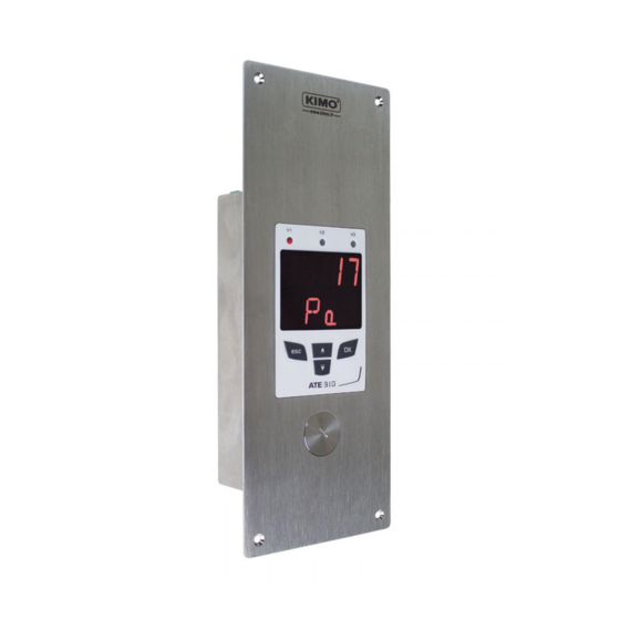
1.1. Transmitter description The ATE310 transmitter can be configured with the keyboard. It is possible to set the measurement units, to activate or not a channel,… Philosophy : the different settings are indicated under a folder and sub folder number form. These digital codes are explained in details in the user manual. -
Page 6: Modbus
2.1. Settings Communication speed : between 2400 and 115200 bauds, 19200 bauds by default • Data Bits : 8 bits • Stop bit : 1 bit • Parity : None • Flow control : None • Transmitter addressing : between 1 and 255 (always answers to requests from address 0) •... - Page 7 Type Size Designation Example Serial number 8 bytes Class (1 byte) '3' (0x33) Range (1 byte) 'F' (0x46) Year (2 bytes) 13 (0x000D) Month (1 byte) 8 (0x08) Number (3 bytes) 98765 (0x0181CD) Format Byte 2 (range) Byte 1 (class) Byte 4 (year) Byte 3 (year) Byte 6 Byte 5...
- Page 8 List of units : Field Unit Value None °C Temperature °F g/kg Kj/KG Hygrometry °C td °F td °C Tw °F Tw inWg mbar Pressure mmHg mmH2O daPa Air velocity km/h Combustion “Enumerations” table : Corresponding values Communication Modbus 2400 4800 9600 19200...
-
Page 9: Access To The Different Functions
This step is necessary for each configuration of the transmitter. To have an access to the transmitter functions, and for security measures, you need to fill in a security code. By default, this security code is 0101. Verify that the transmitter is powered. •... -
Page 10: F 100 : Configure The Transmitter
This folder enables to configure the following parameters of the transmitter : security code, modbus, options and factory configuration. It also enables an access to the serial number and the firmware version of the transmitter. 4.1. Access to the serial number : F100 The serial number enables to obtain activation codes for the options. -
Page 11: Configure The Modbus Communication
4.5. Configure the Modbus communication 4.5.1 Configure the slave number : F150 The F141 sub folder is displayed on the screen. ➢ Press Up key. “F 150” is displayed on the screen. ➢ Press OK. “F150” flashes and the slave number is displayed below (the default number is 1). ➢... -
Page 12: Back To Factory Settings : F190
The “F170” sub folder is displayed on the screen. ➢ Press Up key. “F180” flashes on the screen and “OFF” is displayed below. ➢ Press OK. “OFF” is flashing. ➢ Press up or down keys to display “ON” then press OK. “F180”... -
Page 13: F 200 : Configuration Of The Channels And Measurement Units
This folder allows to activate the channels and to configure the measurement unit for each channel. 5.1. Activate a channel The transmitter is powered on. ➢ Press OK. ➢ Enter the activation code (see page 9). ➢ Press OK. ➢ Press Up key to go to the F 200 folder. ➢... -
Page 14: F 300 : Analog Inputs Management
The ATE310 have 3 analog inputs in standard and a digital input in option. The following configurations are therefore possible : 1. Display of values from a measuring system via the analog inputs and output of the values via the digital output. ➢... -
Page 15: Set The Analog Inputs
6.1. Set the analog inputs The transmitter is powered on. ➢ Press OK. ➢ Enter the activation code (see page 9). ➢ Press OK. ➢ Press Up key to go to the F 300 folder corresponding to the analog input of the channel 1 then press twice OK. “F300”... -
Page 16: Measurements Conversion Tables
➢ Press OK when the last digit is configured. F 302 flashes, the maximum range is configured. To set the maximum and minimum ranges of the channel 2, go to the F 311 (minimum range) and F 312 (maximum range) folders and follow the settings procedure of the channel 1 ranges. To set the maximum and minimum ranges of the channel 3, go to the F 321 (minimum range) and F 322 (maximum range) folders and follow the settings procedure of the channel 1 ranges. -
Page 17: F400 : Alarms Management
Three alarms modes are available : Rising edge (1 threshold) : the alarm goes off when the measurement exceeds the threshold and stops when it • goes back below the threshold. Falling edge (1 threshold) : the alarm goes off when the measurement goes below the threshold and stops when •... - Page 18 OFF : alarm is deactivated • 1/3 : rising edge mode. • 2/3 : falling edge mode • 3/3 : monitoring mode • ➢ Press OK. “F400” flashes. ➢ Press Up key to go to the F401 folder of the alarm 1 (F411 for the alarm 2 and F421 for the alarm 3) then press ➢...
-
Page 19: F 520 : Measurement Setting
8.1. Add a coefficient The correction coefficient allows to adjust the transmitter according to data in pressure of the installation. How to calculate it ? For example, the pressure in your section is 20 Pa and the transmitter indicates 18 Pa. The coefficient to apply is 20 / 18 it means 1.111. -
Page 20: Functions Recap And Modbus Connections
9.1. F 100 : Configure the transmitter Code Register type Modbus Description Possibilities F 100 Real 1000 Transmitter serial number F 101 1010 Firmware version 1020 Device identification 1030 Probe identification F 140 Boolean 1400 Keypad lock 0 : deactivated 1 : activated F 141 1410... -
Page 21: F 300 : Manage The Analogue Inputs
9.3. F 300 : Manage the analogue inputs Code Register type Modbus Description Possibilities F 300 Enumeration* 3000 Channel 1 analogue input 4-20 mA / 0-20 mA / 0-10 V / 0-5 V / 0-2.5 V selection F 310 Enumeration* 3100 Channel 2 analogue input 4-20 mA / 0-20 mA / 0-10 V / 0-5 V / 0-2.5 V... - Page 22 Code Register type Modbus Description Possibilities F 410 Enumeration* 4100 Alarm mode of the alarm 2 OFF: None 1/3 : Rising edge 2/3 : Falling edge 3/3 : Monitoring F 411 4110 Alarm 2 channel selection Channel 1 Channel 2 Channel 3 F 412 Real...
-
Page 23: F 500 : Set The Measurement
9.5. F 500 : Set the measurement Code Register type Modbus Description Possibilities F 520 Real 5200 Channel 1 coefficient From 0.01 to 5 F 530 Real 5300 Channel 2 coefficient From 0.01 to 5 F 540 Real 5400 Channel 3 coefficient From 0.01 to 5 F 521 Real...
Need help?
Do you have a question about the ATE 310 and is the answer not in the manual?
Questions and answers