Table of Contents
Advertisement
Advertisement
Table of Contents

Related Manuals for Kimo C310


Summary of Contents for Kimo C310
- Page 1 Configuration of C310 multifunction transmitters by keypad...
-
Page 3: Table Of Contents
Table of contents 1. Introduction............................5 1.1. Description of the transmitter.......................5 1.2. Description of the keys.........................5 1.3. Protection tips of the sensor......................6 2. Modbus..............................7 2.1. Configuration of parameters......................7 2.2. Functions............................7 2.3. Access code to register........................7 3. Configure the transmitter........................10 3.1. Enter the security code......................10 3.2. -
Page 5: Introduction
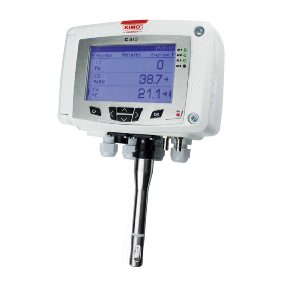
1.1. Description of the transmitter C310 transmitters with display can be configured via keypad. It is possible to set the measurement units, to activate or not a channel,... 05/02/14 9.53 ◄Min/max Mesures Graphique► Alarm lights Left key Indicator light Esc key... -
Page 6: Protection Tips Of The Sensor
1.3. Protection tips of the sensor Sensitive It's extremely unwise to remove the protection tip of our hygrometry probes as element Protection tip the sensitive element is very fragile even to light contacts. However, if you to unscrew have to remove the protection tip, take all possible precautions and avoid any contact with the sensitive element. -
Page 7: Modbus
2.1. Configuration of parameters Communication speed : between 2400 and 115200 bauds, 19200 bauds by default • Data bits : 8 bits • Stop bit : 1 bit • Parity : None • Flow control : None • Transmitter addressing : between 1 and 255 (automatically answers the requests from address 0) •... - Page 8 Unit – Modbus code : 7030 (channel 1) • 7060 (channel 2) 7090 (channel 3) 7120 (channel 4) List of units : Field Unit Value Field Unit Value None None °C Temperature Air velocity °F km/h G/Kg m3/h Kj/KG °C td Airflow Hygrometry °F td...
- Page 9 Unit : code 7030, U8 type • Byte 1 0001 0000 Unit value : 16 : °C (See table “List of units” p8) “Enumerations” table : Corresponding values Backlight duration Permanent Graphical period 3 mn 15 mn 30 mn 1 hour 3 hours 6 hours hours...
-
Page 10: Configure The Transmitter
3.1. Enter the security code To configure the transmitter, and for security purposes, a security code must be entered. The default code is 0101. ➢ Connect the transmitter. ➢ Wait until the initializing period is over. ➢ Press OK. “Code” is displayed with “0000” below. ➢... -
Page 11: Set The Screen
3.2.1 Set the screen ➢ Press OK on “Screen” line. ➢ Press OK on “Contrast” line to set the contrast between 0 and 3. ➢ Use Up and Down keys to set the contrast then press OK. ➢ Go to the “Backlight settings” line with the Down key then press OK. ➢... -
Page 12: Modify The Security Code
3.2.7 Modify the security code ➢ Press OK on “Security code” line. The following message is displayed : “Modification Security code?”. ➢ Go to “Continue” then press OK. ➢ Enter the current code. ➢ Enter the new code. ➢ Go to “YES” then press OK to confirm the new code. The transmitter displays a message indicating that the code has been modified. -
Page 13: Access To The Transmitter Information
3.2.11 Access to the transmitter information This part allows to access to the information about the transmitter, the boards and the probes. ➢ Press OK on “Information” line. screen is displayed with information about the transmitter (name, serial number, calibration date). ➢... -
Page 14: Set The Minimum And Maximum Ranges
The transmitter displays the different types of outputs : 4-20 mA, 0-20 mA, 0-10 V or 0-5 V. ➢ Go to the type of required output then press OK. The output number is equivalent to the number of the displayed channel (ex : output 1 = channel1) 3.4.2 Set the minimum and maximum ranges ➢... -
Page 15: Configure The Alarms
3.5. Configure the alarms This part allows to activate and define the alarms conditions on one or several channels. One channel must be configured at least (see chapter 3.3). If no channel has been configured, the transmitter will indicate that the alarms configuration is impossible. -
Page 16: Set The Alarm In Rising Or Falling Edge
Monitoring The alarm goes off when the measurement is outside the low and high thresholds. When an audible alarm goes off, it is possible to acknowledge it pressing OK key on the transmitter. 3.5.2 Set the alarm in rising or falling edge The alarm mode “Rising edge”... -
Page 17: Configure The Relays (Optional)
The alarm mode “Transmitter state” is selected. ➢ Go to the “Configuration” line then press OK. ➢ Press OK on the “Condition selection” line. The transmitter displays the list of alarms conditions : Ambient temperature too high* • Ambient temperature too low* •... -
Page 18: Configure The Probes, Boards And Normative Values
3.6. Configure the probes, boards and normative values This part allows to set the following parameters : for an air velocity and airflow probe : (hotwire or vane) : the type of section, the correction factor, the in air • velocity and the compensation in atmospheric pressure (only available for hotwire probes) For a pressure board : air velocity and airflow (if the option is activated), the integration in pressure, the purge •... -
Page 19: Configure A Co2 Probe Or A Temperature/Hygrometry Probe
New displayed value = [((10 - Coef.) x New Value) + (Coef. x Old value)] /10 Example : C310 with hotwire (0-30 m/s) – Current measurement : 2 m/s – New measurement : 8 m/s The air velocity source being unstable, the user selects a strong integration. Integration : 7. The variation is lower than 10 m/s, it is possible to apply the integration calculation formula. - Page 20 ➢ Go to “Board” line then press OK. ➢ Go to “Air velocity/airflow” line then press OK. ➢ Press OK on “Measure mean” line then use Up and Down arrows to select : Pitot tube L (coefficient : 1.0015) • Pitot tube S (coefficient : 0.84) •...
- Page 21 Auto (probe 1) : the transmitter will take into account the measured temperature by a temperature probe • connected to the transmitter at the location “Probe 1”. ➢ Go to “Atmo pressure” line then select the unit with Up and Down keys. ➢...
-
Page 22: Activate An Option
10 – Wait for 3 seconds. • 11 – Recovery of the measurement. • ➢ Press OK. ➢ Enter the security code then press OK. ➢ Go to the “Parameters” line then press OK. ➢ Go to “Board” line then press OK. ➢... - Page 23 The transmitter displays asking if you want to activate the option. ➢ Go to “Continue” then press OK. The transmitter asks for an activation code. ➢ Enter the supplied activation code then press OK.
-
Page 24: Description Of Function And Modbus Connections
4.1. Device Modbus Register type Description Possibilities 1000 Serial number of the transmitter 1010 Firmware version 1400 Keypad locking 0 : deactivated 1 : activated 1410 Security code 1500 Modbus slave number From 1 to 255 1510 Enumeration Modbus speed 2400 / 4800 / 9600/ 19200 / 38400 / communication 115200 bds... -
Page 25: Outputs
4.3. Outputs Modbus Register type Description Possibilities 3000 Enumeration Analogue output selection of the channel 4-20 mA / 0-20 mA / 0-10 V / 0-5 V 3100 Enumeration Analogue output selection of the channel 4-20 mA / 0-20 mA / 0-10 V / 0-5 V 3200 Enumeration Analogue output selection of the channel... -
Page 26: Alarms
4.4. Alarms Modbus Register type Description Possibilities 4000 – 4100 – 4200 Enumeration Alarm mode Rising edge Falling edge Monitoring 4010 – 4110 – 4210 U8 Channel selection Channel 1 Channel 2 Channel 3 4020 – 4120 – 4220 Real Threshold 1 setting According to connected probe 4030 –...
Need help?
Do you have a question about the C310 and is the answer not in the manual?
Questions and answers