
Related Manuals for Kimo CPE 300


Summary of Contents for Kimo CPE 300
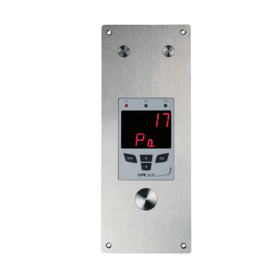
- Page 1 User Manual Pressure • Temperature • Humidity • Air Velocity • Air Flow Flush-mount transmitter CPE 300 MODBUS system MODBUS system MODBUS system Remote control Remote control Remote control...
-
Page 3: Table Of Contents
................CPE 300 transmitter configuration via remote control / Modbus... -
Page 4: Prerequisite
Channel selection With this selector, you can swap the transmission channel so that it matchs with the transmitter reception channel. See page 6 to configure the transmitter reception channel. Page 1 CPE 300 transmitter configuration via remote control / Modbus... -
Page 5: B - Output Signal Selection
With the on-off switch located on the left top of the transmitter (when open), you can choose analogue output 0-10V (voltage) or 4-20 mA (current) Down 4-20 mA 0-10 V Page 2 CPE 300 transmitter configuration via remote control / Modbus... -
Page 6: Modbus Parameters
Tw) 10 PSI 21 °F (humid temp. Tw) If the value measured is equal to 623 : 11 Pa 22 KJ/Kg (Enthalpy i) Résultat => 62.3 mmH O Page 3 CPE 300 transmitter configuration via remote control / Modbus... -
Page 7: Access Codes To Registers
(sequel) • Serial number of SPI sensing element Modbus code: 1402 Other access codes to different registers are indicated on each function at stage n°2. Shown as this pictogram: Page 4 CPE 300 transmitter configuration via remote control / Modbus... - Page 8 Once the folder is selected, press to validate. On the top left of each page of this manual, you can find a reminder of the configuration folder where the function is available. F400 Page 5 CPE 300 transmitter configuration via remote control / Modbus...
-
Page 9: Display Configuration • F100
> • press twice to return to reading mode. • press once to return to another folder selection. • with keys to choose another sub-folder from the folder 100. Page 6 CPE 300 transmitter configuration via remote control / Modbus... - Page 10 > • press twice to return to reading mode. • press once to return to another folder selection. • with keys to choose another sub-folder from the folder 200. CPE 300 transmitter configuration via remote control / Modbus Page 7...
-
Page 11: Analogue Output Management • F300
On the photo alongside, the multimeter is connected to the 0-10 V output. RS 232 connectors LCC 300 software Pressure connection Analogue Power supply Relays output terminal blocks Page 8 CPE 300 transmitter configuration via remote control / Modbus... - Page 12 > • press twice to return to reading mode. • press once to return to another folder selection. • with keys to choose another sub-folder from the folder 300. Page 9 CPE 300 transmitter configuration via remote control / Modbus...
-
Page 13: B - Analogue Output Settings
300. After an analogue output setting, if the unit of measurement is modified (see page 5), you have to reconfigure the outputs according to the new unit of measurement. Page 10 CPE 300 transmitter configuration via remote control / Modbus... - Page 14 CPE 302 0 to ±500 0 to ±51 0 to ±2 0 to ±5 CPE 303 0 to 1000 ± 0 to ±102,0 0 to ±4,02 0 to ±10,00 Page 11 CPE 300 transmitter configuration via remote control / Modbus...
-
Page 15: Alarm / Relay Settings • F400
• press twice on to return to reading mode. • press once on to return to another folder selection. • with keys, you can choose another sub-folder from the folder 400. Page 12 CPE 300 transmitter configuration via remote control / Modbus... -
Page 16: C - Alarm / Relay Functions And Led Colour Codes
Audible alarm Once the alarm is activated, an alarm sounds whilst the setpoint is reached. The BEEP alarm function must be activated to use the audible alarm. See page 12. Page 13 CPE 300 transmitter configuration via remote control / Modbus... -
Page 17: D - Alarm Mode Details
Setpoint 2 > Setpoint 1 Measurement Alarm set <T> Time-delay Setpoint 2 Setpoint 1 <T> <T> <T> Time Energized Relay status Negative security Not energized Relay status Energized Positive security Not energized Page 14 CPE 300 transmitter configuration via remote control / Modbus... - Page 18 Configuration N°3 : 1 setpoint, time-delay and falling action activated Measurement Alarm set <T> Time-delay Setpoint 1 <T> <T> <T> Time Relay status Energized Negative security Not energized Relay status Energized Positive security Not energized Page 15 CPE 300 transmitter configuration via remote control / Modbus...
-
Page 19: E - Alarm Mode Selection
• press twice to return to reading mode. • press once to return to another folder selection. • with keys, you can choose another sub-folder from the folder 400. Page 16 CPE 300 transmitter configuration via remote control / Modbus... -
Page 20: F - Setpoinst And Time-Delay Setting
If after having set up a setpoint, the unit of measurement is modified (see page 9), then you have to reconfigure the setpoints according to this new unit of measurement. Page 17 CPE 300 transmitter configuration via remote control / Modbus... - Page 21 • press twice to return to reading mode. • press once to return to another folder selection. • with keys , you can choose another sub-folder from the folder 400. Page 18 CPE 300 transmitter configuration via remote control / Modbus...
-
Page 22: Pressure Measurement Configuration • F500
• press twice to return to reading mode. • press once to return to another folder selection. • with keys , you can choose another sub-folder from the folder 500. Page 19 CPE 300 transmitter configuration via remote control / Modbus... -
Page 23: B - Time-Delay Between 2 Self-Calibrations
• with keys , you can choose another sub-folder from the folder 500 Whenever you want, in reading mode, you can carry out a self-calibration by keeping “ESC” pressed Page 20 CPE 300 transmitter configuration via remote control / Modbus... -
Page 24: Other Functions
9.a- Activation / deactivation of the RS232 and home bus CPE 300 transmitters have one RS232 and one RS 485 digital output (Modbus protocol) - optional. With the RS 232, you can display 1 or 2 parameters which are measured by other Class 200 and 300 transmitters, or you can send measurements to be displayed on another Class 300 transmitters. -
Page 25: C- Modification Of Modbus Communication Speed
Step > • press twice to return to reading mode. • press once to return to another folder selection. • with keys, choose another sub-folder from the folder 300 Page 22 CPE 300 transmitter configuration via remote control / Modbus... - Page 26 > Step • press twice to return to reading mode. • press once to return to another folder selection. • with , choose another sub-folder from the folder 300. Page 23 CPE 300 transmitter configuration via remote control / Modbus...
-
Page 27: Error Codes
300. 10. Error codes Problem : • Interchangeable Measuring Sensor (SPI element) not connected Solution : • Connect the probe / SPI (see SPI notice) Page 24 CPE 300 transmitter configuration via remote control / Modbus... -
Page 28: Functions Recap
01 to 9999 minutes Time-delay after purge from 00 to 60 seconds Code Description Available settings 1000 Measurement integration from 0 to 9 1002 Self-calibration for time-delay from 0 to 60 minutes Page 25 CPE 300 transmitter configuration via remote control / Modbus... - Page 29 2=> setpoint 1, time-delay and rising action 3=> setpoint 1, time-delay and falling action Setpoint 1 of Relay 2 Setpoint 2 of Relay 2 Time-delay on Relay 2 from 0 to 60 seconds Page 26 CPE 300 transmitter configuration via remote control / Modbus...
- Page 30 NOTES... Page 25 CPE 300 transmitter configuration via remote control / Modbus...
- Page 31 NOTES... Page 26 CPE 300 transmitter configuration via remote control / Modbus...
Need help?
Do you have a question about the CPE 300 and is the answer not in the manual?
Questions and answers