Sign In
Upload
Download
Table of Contents
Contents
Add to my manuals
Delete from my manuals
Share
URL of this page:
HTML Link:
Bookmark this page
Add
Manual will be automatically added to "My Manuals"
Print this page
×
Bookmark added
×
Added to my manuals
Manuals
Brands
Kimo Manuals
Transmitter
CPE 311-S
User manual
Kimo CPE 311-S User Manual
Configuration of transmitters by keypad
Hide thumbs
1
2
Table Of Contents
3
4
5
6
7
8
9
10
11
12
13
14
15
16
17
18
19
20
21
22
23
24
25
26
27
28
page
of
28
Go
/
28
Contents
Table of Contents
Bookmarks
Table of Contents
Table of Contents
1 Introduction
Description of the Transmitter
Description of the Keys
Protection Tips of the Sensor
2 Modbus
Configuration of Parameters
Functions
Access Code to Register
3 Access to the Different Functions
4 F 100: Configure the Transmitter
Access to the Serial Number: F100
Access to the Firmware Version: F101
Lock the Keypad: F 140
Modify the Safety Code: F141
Configure the Modbus Communication (Optional)
Set the Slave Number: F150
Set the Speed Communication: F151
Activate the Options
Back to Factory Settings: F190
5 F 200: Configuration of the Channels and Measurement Units
Activate a Channel
Assign a Measurement Unit to a Channel
6 F 300: Manage the Analogue Outputs
Set the Analogue Outputs
Set the Ranges of the Analogue Outputs
Output Diagnostic
Connection Configuration
Perform the Output Diagnostic
7 F400: Manage the Alarms
8 F 500: Set the Pressure Measurement
Perform an Auto-Zero
Integration of the Pressure Measurement
Delay Times between 2 Auto-Zeros
Add a Coefficient
Add an Offset
9 Functions Recap and Modbus Connections
F 100: Configure the Transmitter
F 200: Configure the Channels and the Measurement Units
F 300: Manage the Analogue Outputs
F 400: Manage the Alarms
F 500: Set the Measurement
Advertisement
Quick Links
1
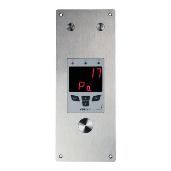
Description of the Transmitter
2
Configuration of Parameters
Download this manual
Configuration of CPE 310-S and CPE 311-S
transmitters by keypad
Table of
Contents
Previous
Page
Next
Page
1
2
3
4
5
Advertisement
Table of Contents
Need help?
Do you have a question about the CPE 311-S and is the answer not in the manual?
Ask a question
Questions and answers
Related Manuals for Kimo CPE 311-S
Transmitter Kimo CPE 300 User Manual
Flush-mount transmitter (32 pages)
Transmitter Kimo C310 User Manual
Configuration of multifunction transmitters by keypad (32 pages)
Transmitter Kimo Class 300 User Manual
(44 pages)
Transmitter Kimo CPE 310-S User Manual
Configuration of transmitters by keypad (28 pages)
Transmitter Kimo Class 200 User Manual
(40 pages)
Transmitter Kimo CP200 User Manual
(40 pages)
Transmitter Kimo CP 111 Technical Data Sheet
Differential pressure transmitter (4 pages)
Transmitter Kimo CA 310 User Manual
Configuration transmitters by keypad (32 pages)
Transmitter Kimo CP211-R User Manual
Configuration of class 210-r transmitters by keypad (32 pages)
Transmitter Kimo CP212-R User Manual
Configuration of class 210-r transmitters by keypad (32 pages)
Transmitter Kimo 210-R Series User Manual
Configuration of class 210-r transmitters by keypad (32 pages)
Transmitter Kimo CTV210-R User Manual
Configuration of class 210-r transmitters by keypad (32 pages)
Transmitter Kimo ATE 310 User Manual
Transmitters configuration by keypad (24 pages)
Transmitter Kimo HM 50 Technical Data Sheet
Humidity transmitter (4 pages)
Transmitter Kimo TG 100 Technical Data Sheet
Temperature transmitter (4 pages)
This manual is also suitable for:
Cpe 310-s
Table of Contents
Print
Rename the bookmark
Delete bookmark?
Delete from my manuals?
Login
Sign In
OR
Sign in with Facebook
Sign in with Google
Upload manual
Upload from disk
Upload from URL


Need help?
Do you have a question about the CPE 311-S and is the answer not in the manual?
Questions and answers