Advertisement
Quick Links
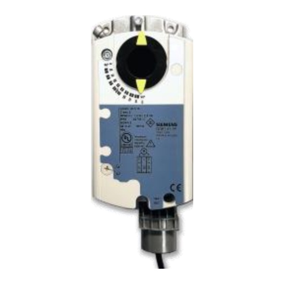
™
OpenAir
GLB Series
Enhanced Non-spring Return Rotary
Description
The OpenAir direct coupled enhanced non-spring return rotary electric actuators are
designed for two-position/floating or modulating control of dampers.
Features
Application
These actuators are used in constant or variable air volume installations for control of
HVAC dampers requiring up to 88 lb-in (10 Nm) of torque.
Product Numbers
Torque
Product Number
GLB141.1P
GLB141.1Q
GLB146.1P*
88 lb-in
GLB341.1U
(10 Nm)
GLB346.1U*
GLB161.1P
GLB166.1P*
GLB161.1Q
* For conduit adaption, order an ASK76.1U Conduit Adapter. See Accessories.
Electronic Damper Actuators
Selectable modulating control signal (0 to 10 Vdc or 2 to 10 Vdc).
24 Vac/dc compatible.
New line voltage (34x models) for 100 to 240 Vac two-position/floating control.
Integral 1/2-inch conduit connection.
Manual override.
Independently adjustable dual auxiliary switches available.
cUL and UL listed;
certified
Control
Signal
2-position/
Floating
Modulating
0(2) to 10 Vdc
Technical Instructions
Document No. 155-785
Table 1.
Dual
Feedback
Auxiliary
Switches
—
—
—
—
—
•
—
—
—
•
•
—
•
•
•
—
January 20, 2017
Pre-Cabled Power Supply
Plenum
24 Vac/dc
6-ft length
Plenum
Standard
100 to 240 Vac
Standard
Plenum
Plenum
24 Vac/dc
6-ft length
Siemens Industry, Inc.
Advertisement

Related Manuals for Siemens OpenAir GLB141.1P


Summary of Contents for Siemens OpenAir GLB141.1P
- Page 1 (10 Nm) — • GLB346.1U* Standard • — GLB161.1P Plenum • • GLB166.1P* Modulating Plenum 24 Vac/dc • — 0(2) to 10 Vdc GLB161.1Q 6-ft length * For conduit adaption, order an ASK76.1U Conduit Adapter. See Accessories. Siemens Industry, Inc.
-
Page 2: Specifications
95° Shaft size: Minimum shaft length 3/4-inch (20 mm) Mounting Figure 1. Acceptable Shaft Sizes. Enclosure NEMA Type 2 Housing IP54 according to EN60529 (Not with cable-up mounting orientation) Material Durable plastic Gear lubrication Silicone-free Page 2 Siemens Industry, Inc. - Page 3 All other standard actuator models have built-in conduit adapters. Figure 2. Conduit Adapter. ASK71.5: Allows a direct-coupled actuator to provide an auxiliary linear drive. Figure 3. Rotary-to-Linear. Siemens Industry, Inc. Page 3...
- Page 4 ASK75.7U Weather Shield and outdoor-rated conduit fittings. This weather shield may be mounted in any orientation. Figure 7. NEMA Type 4X Weather Shield. For dimensions, see Figure 27. Page 4 Siemens Industry, Inc.
- Page 5 10. Auxiliary Switch B 11. Position indicator 12. Adjustment lever with locking screw (4 mm hex) 13. Set screw for mechanical range stop (4 mm hex) Figure 8. Parts of the Actuator. 14. Mounting bracket Siemens Industry, Inc. Page 5...
-
Page 6: Operation
In the event of a power failure, the actuator holds its position. In the event that only the control signal is lost, the actuator returns to the 0 position. Life expectancy An improperly tuned loop will cause excessive repositioning that will shorten the life of the actuator. Page 6 Siemens Industry, Inc. - Page 7 ) to point to the position of Switch A. Use AUX SWITCH ADJUSTMENT the narrower tab on the red ring to point to the position of Switch B. Rotation Direction GLB14x.1P, GLB34x.1U Two-position/Floating Control Figure 11. Setting the Rotation Direction. Siemens Industry, Inc. Page 7...
- Page 8 0 to 10 Vdc or a 2 to 10 Vdc signal, within the adjusted mechanical range. The feedback signal will also reflect the control signal selected, either a 0 to 10 Vdc or a 2 to 10 Vdc. Page 8 Siemens Industry, Inc.
-
Page 9: Mounting And Installation
Use the shaft insert supplied for any Guide 3/8-inch (8 to 10mm) diameter shaft Figure 15. Damper Shaft Sizes. NOTE: For all damper shafts with the exception of the 1/2-inch round shaft: Remove the 1/2-inch Ø factory-installed guide before installation. Siemens Industry, Inc. Page 9... - Page 10 The sum of the VA ratings of all actuators and all other components powered by one transformer must not exceed the rating of the transformer. It is recommended that one transformer power no more than 10 actuators. Page 10 Siemens Industry, Inc.
- Page 11 Switch B Common Black/red Figure 18. GLB14x Wiring Diagram. Switch B N.C. Black/blue Switch B N.O. Black/pink Figure 19. 2-Position, SPST (Single-Pole, Single-Throw). Figure 21. Floating Control, 24 Vac/dc. Figure 20. 2-Position, SPDT (Single-Pole, Double-Throw). Siemens Industry, Inc. Page 11...
- Page 12 Factory-installed Options Switch A Common Gray/Red Switch A - NC Gray/Blue Switch A - NO Gray/Pink Figure 26. GLB16x Wiring. Switch B - Common Black/Red Switch B - NC Black/Blue Switch B - NO Black/Pink Page 12 Siemens Industry, Inc.
-
Page 13: Troubleshooting
Connect wires S4 and S5 to the DMM. The DMM should indicate an open circuit or no resistance. Apply a control signal to wires 1 (red) and 7 (orange). The DMM should indicate contact closure as the actuator shaft coupling reaches the setting of Switch B. Siemens Industry, Inc. Page 13... - Page 14 Connect wires S4 and S5 to the DMM. The DMM should indicate open circuit or no resistance. Apply a control signal (100 to 240 Vac) to wires 4 (light blue) and 7 (white) The DMM should indicate contact closure as the actuator shaft coupling reaches the setting of Switch B. Page 14 Siemens Industry, Inc.
- Page 15 OpenAir™ GLB Enhanced Non-Spring Return Rotary Electronic Damper Actuator Technical Instructions Document Number 155-785 January 20, 2017 Start-Up/ Connect a Digital Multimeter (DMM) to the supply voltage wires. Commissioning Verify that the supply voltage is between 19.2 and 28.8 Vac/dc. 24 Vac/dc Turn off the power supply.
- Page 16 Information in this publication is based on current specifications. The company reserves the right to make changes in specifications and models as design improvements are introduced. OpenAir is a trademark of Siemens Schweiz AG. Other product or company names mentioned herein may be the trademarks of their respective owners.
Need help?
Do you have a question about the OpenAir GLB141.1P and is the answer not in the manual?
Questions and answers