Advertisement
Table of Contents
- 1 Table of Contents
- 2 Important Safety Notices
- 3 Exercise Guidelines
- 4 Warning Label Placement
- 5 Free and Training Area
- 6 Important Assembly Information
- 7 Cable Assembly Instruction
- 8 Weight Capacity and Dimension
- 9 Care and Maintenance
- 10 Operating Notes
- 11 Weight Resistance Chart
- 12 Bench Parts List
- 13 Bench Exploded Diagram
- 14 Warranty
- 15 Ordering Parts
- Download this manual
NOTE:
Please read all
instructions carefully
before using this product
Table of Contents
Safety Notice
Important Assembly
Information
Care and Maintenance
Parts List
Warranty
Ordering Parts
Model
RS7000
Retain This
Manual for
Reference
161202
OWNER'S
MANUAL
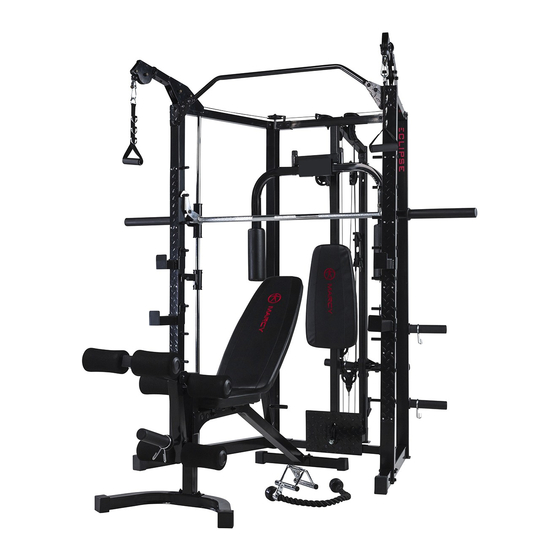
MARCY RS7000
DELUXE SMITH CAGE
IMPORTANT:
Please read this manual before commencing
assembly of this product.
Advertisement
Table of Contents

Related Manuals for Marcy RS7000


Summary of Contents for Marcy RS7000
- Page 1 NOTE: Please read all instructions carefully before using this product MARCY RS7000 DELUXE SMITH CAGE Table of Contents Safety Notice Important Assembly Information Care and Maintenance Parts List Warranty Ordering Parts Model RS7000 Retain This Manual for Reference 161202 IMPORTANT:...
-
Page 2: Table Of Contents
ORDERING PARTS..................…………..27 BEFORE YOU BEGIN Thank you for selecting the MARCY RS7000 Deluxe Smith Cage. For your safety and benefit, read this manual carefully before using the equipment. As the official distributor for Marcy, we are committed to providing complete customer satisfaction. -
Page 3: Important Safety Notices
IMPORTANT SAFETY NOTICE This exercise equipment is built for optimum safety. However, certain precautions apply whenever you operate a piece of exercise equipment. Be sure to read the entire manual before you assemble or operate your equipment. In particular, note the following safety precautions: 1. -
Page 4: Exercise Guidelines
EXECISE GUIDELINES Building Muscle and Gaining Weight Unlike aerobic exercise, which emphasizes endurance training, anaerobic exercise focuses on strength training. A gradual weight gain can occur while building the size and strength of muscles. While developing muscle mass, your body adapts to the stress placed upon it. You can modify your diet to include foods such as meat, fish and vegetables. - Page 5 Beginning a Strength Building Program Warming Up To begin strength training, it is important to stretch and perform light exercise for 5 to 10 minutes. This helps prepare the body for more strenuous exercise by increasing circulation, raising your body temperature and developing more oxygen to your muscles.
-
Page 6: Warning Label Placement
WARNING LABEL PLACEMENT www.puretecfitness.com... -
Page 7: Free And Training Area
FREE AND TRAINING AREA www.puretecfitness.com... -
Page 8: Important Assembly Information
IMPORTANT ASSEMBLY INFORMATION Tools required for assembling the bench: Two adjustable Wrenches and Allen wrenches. NOTE: It is strongly recommended that this equipment be assembled by two or more people to avoid possible injury. Ensure Carriage Bolts are inserted through the SQUARE holes on components that need to be assembled. - Page 9 Assemble Sliding Weight Post in assembly Step-6 The triangular bracket on the Sliding Weight Post (Part #23) must be facing up and toward to back. Weight Bar Assembly Note NOTE: Help of another person is strongly recommended for this step. Place the Lifting Sleeve (#28) in between the two Safety Stop Frames (#25).
-
Page 10: Cable Assembly Instruction
SMITH MACHINE CABLE ASSEMBLY INSTRUCTION Cable Loop Diagram www.puretecfitness.com... - Page 11 Butterfly Cable assembly instruction Step-11 A.) Attach one end of 113” Butterfly Cable (#45) to the clip on Right Butterfly (#13). Draw the Cable to the right Swivel Pulley Bracket (#15). B.) Attach a Pulley (#62) and two Cable Retainers (#78) to the Bracket. Secure them with one M10 x 2”...
- Page 12 Upper Cable assembly instruction Step-12 A.) Attach one Cross-over Swivel Pulley Bracket (#10) to right Upper Side Frame (#7). Secure it with four M8 x ⅜” Allen Bolts (#101) and four Ø ⅝” Washers (#106). B.) Attach a Pulley (#62) to the right Swivel Bracket and secure it with one M10 x 1 ¾” Allen Bolt (#93), two Ø...
- Page 13 www.puretecfitness.com...
- Page 14 Upper Cable assembly instruction Step-12A A.) Attach a Pulley (#62) to the open pulley shaft. Secure it with one M10 x 1 ¾” Allen Bolt (#93), one Ø ¾” Washer (#107), and one Cable Retainer (#78). B.) Draw the Cable around the Pulley then to the next open pulley shaft on Rear Upper Frame (#18). Attach a Pulley to the open shaft.
- Page 15 www.puretecfitness.com...
- Page 16 Upper Cable assembly instruction Step-12B A.) Attach a Small Pulley to the opening on left Upper Side Frame (#7). Secure the Small Pulley with one M10 x 2 ¾” Allen Bolts (#97), two Ø ¾” Washers (#107), and one M10 Aircraft Nut (#110). B.) Draw the Cable under the Small Pulley and then pull up.
- Page 17 www.puretecfitness.com...
- Page 18 Sliding Weight Post Cable assembly instruction Step-13 A.) Attach one end of the 97” Sliding Weight Post Cable (#46) to the triangular bracket on the Sliding Weight post (#23). Secure it with one M10 x ¾” Allen Bolt (#90), two Ø ¾” Washers (#107), and one M10 Aircraft Nut (#110).
- Page 19 www.puretecfitness.com...
- Page 20 Lower Cable assembly instruction Step-14 A.) Insert the tip of the 152” Lower Cable (#44) through the opening on Foot Plate (#32) to the opening on bottom of Middle Vertical Frame (#9). B.) Attach a Pulley (#62) to the opening. Secure it with one M10 x 2 ½” Allen Bolt (#95), two Ø 1” x ½” Pulley Bushings (#57), and one M10 Aircraft Nut (#110).
- Page 21 www.puretecfitness.com...
-
Page 22: Weight Capacity And Dimension
WEIGHT CAPACITY AND DIMENSION 1. Maximum user weight: 136kgs. 2. Maximum weight on Sliding Weight Post (#23): 136kgs (68kgs on each side) 3. Maximum weight on storage Weight Post (#38): 45kgs 4. Maximum weight on Bar Holder (#21 & #22) and Safety Catch (#19 & #20): 136kgs 5. -
Page 23: Operating Notes
OPERATION NOTES This equipment should be placed on flat surface. The incline or decline of surface should be limited to 3% or less for best performance and safety. Cable Tension Adjustment Adjust the tension of the Cable System by moving the position of lower Pulley on the Double Floating Pulley Brackets. -
Page 24: Weight Resistance Chart
RS7000 WEIGHT RESISTANCE CHART Station Ratio Example 100% 4.5kg. plate creates 4.5kg. resistance Low Pulley 100% 4.5kg. plate creates 2.25kg resistance Butterfly (both arms) 4.5kg. plate creates 2.25kg resistance Left Cross-Over 4.5kg. plate creates 2.25kg resistance Right Cross-Over *Numbers are approximate. Actual resistance may vary. - Page 25 RS7000 CAGE PARTS LIST PART NO DESCRIPTION SIZE QUANTITY Front Left Vertical Frame Front Right Vertical Frame Rear Left Vertical Frame Rear Right Vertical Frame Base Frame Rear Top Beam Upper Side Frame Rear Base Frame Middle Vertical Frame Cross-over Swivel Pulley Bracket...
- Page 26 Cable Roller Upper Cable Sleeve Lower Cable 152” Butterfly Cable 113” Sliding Weight Post Cable 97” Upper Cable 266” Base Frame End Cap 2 ¾” x 2” Left Chin-up Bracket Right Chin-up Bracket Front Vertical Frame Panel Angled Floating Pulley Bracket Triceps Rope Shiver Bar Rotate Ring...
- Page 27 End Cap Ø 1 ½” M10 x 1 ⅝” Carriage Bolt M10 x ⅝” Allen Bolt Carriage Bolt M10 x 2 ½” Carriage Bolt M10 x 3” Allen Bolt M10 x ¾” Allen Bolt M10 x 1” M10 x 1 ⅛” Allen Bolt Allen Bolt M10 x 1 ¾”...
- Page 28 RS7000 CAGE EXPLODED DIAGRAM www.puretecfitness.com...
-
Page 29: Bench Parts List
RS7000 BENCH PARTS LIST PART NO DESCRIPTION SIZE QUANTITY Main Frame Front Post Rear Stabilizer Seat Bracket Leg Developer Leg Developer Weight Post Backrest Support Incline Support Front Stabilizer Seat Pad Backrest Board ⅝” x 1 ⅛” End Cap Foam Tube... -
Page 30: Bench Exploded Diagram
RS7000 BENCH EXPLODED DIAGRAM www.puretecfitness.com... -
Page 31: Warranty
LIMITED WARRANTY Pure-Tec warrants this product to be free from defects in workmanship and material, under normal use and service conditions. Please refer to www.puretecfitness.com for warranty terms. This warranty extends only to the original purchaser and is valid for home use only. Pure-Tec’s obligation under this Warranty is limited to replacing damaged or faulty parts at Pure-Tec’s option.
Need help?
Do you have a question about the RS7000 and is the answer not in the manual?
Questions and answers