National Instruments SCB-68 User Manual
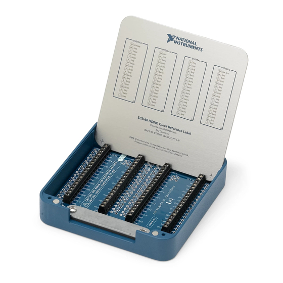
68-pin shielded desktop connector block
Hide thumbs
Also See for SCB-68:
- User manual (104 pages) ,
- User manual (8 pages) ,
- Getting started (10 pages)
Table of Contents
Advertisement
Quick Links
Download this manual
See also:
User Manual
Advertisement
Table of Contents

Related Manuals for National Instruments SCB-68


Summary of Contents for National Instruments SCB-68
- Page 1 SCB-68 User Manual for Advanced Functions 68-Pin Shielded Desktop Connector Block SCB-68 User Manual for Advanced Functions March 2009 372551A-01...
- Page 2 Thailand 662 278 6777, Turkey 90 212 279 3031, United Kingdom 44 (0) 1635 523545 For further support information, refer to the Technical Support and Professional Services appendix. To comment on National Instruments documentation, refer to the National Instruments Web site at and enter ni.com/info the info code feedback ©...
- Page 3 Warranty The SCB-68 is warranted against defects in materials and workmanship for a period of one year from the date of shipment, as evidenced by receipts or other documentation. National Instruments will, at its option, repair or replace equipment that proves to be defective during the warranty period.
- Page 4 Conventions The following conventions are used in this manual: <> Angle brackets that contain numbers separated by an ellipsis represent a range of values associated with a bit or signal name—for example, AO <3..0>. » The » symbol leads you through nested menu items and dialog box options to a final action.
-
Page 5: Table Of Contents
Temperature Sensor Output and Accuracy ..............2-2 Thermocouple Sources of Error..................2-3 Open Thermocouple Detection ..................2-4 Thermocouple Input Filtering ..................2-5 Chapter 3 Soldering and Desoldering Components on the SCB-68 Soldering Equipment .....................3-1 Removing the SCB-68 Board from the Base..............3-1 Soldering and Desoldering Guidelines ................3-2 Chapter 4 Adding Components for Special Functions Channel Pad Configurations ..................4-1... - Page 6 Voltage Dividers for Analog Input ........... 4-36 Voltage Dividers for Analog Output ..........4-37 Voltage Dividers for Digital Inputs ..........4-37 Adding Power Filters..................... 4-38 Appendix A Specifications Appendix B Technical Support and Professional Services Index SCB-68 User Manual for Advanced Functions ni.com...
- Page 7 Introduction The SCB-68 is a shielded I/O connector block with 68 screw terminals for easy signal connection to a National Instruments 68-pin or 100-pin DAQ device. The SCB-68 features a general breadboard area for custom circuitry and sockets for interchanging electrical components. These sockets or component pads allow filtering, 4 to 20 mA current input measurement, open thermocouple detection, and voltage attenuation.
-
Page 8: Introduction
• Appendix A, Specifications Related Documentation For more information about using the SCB-68 with your DAQ device, refer to the following resources: • Documentation for your DAQ device at ni.com/manuals •... -
Page 9: Temperature Sensor And Thermocouple
Diagram. To power the temperature sensor, set switches S1, S2, and S3 for single-ended or differential mode as described in the Using the SCB-68 with MIO DAQ Devices section of the SCB-68 User Guide. This configuration also powers the signal conditioning area and circuitry. Refer to Figure 4-1,... -
Page 10: Temperature Sensor Output And Accuracy
CJC with the SCB-68 is accurate only if the temperature sensor reading is close to the actual temperature of the screw terminals. Therefore, when reading thermocouples, keep the SCB-68 away from drafts or other temperature gradients, such as those caused by heaters, radiators, fans, and warm equipment. -
Page 11: Thermocouple Sources Of Error
The temperature sensor on the SCB-68 is specified to be accurate to ±1 °C. You can minimize temperature differences between the temperature sensor and the screw terminals by keeping the SCB-68 away from drafts, heaters, and warm equipment. -
Page 12: Open Thermocouple Detection
Leave the 0 Ω resistors at positions F and G in place for each channel used. Refer to Table 4-1, Analog Input Channels Component Locations, for component positions for all analog input channels. SCB-68 User Manual for Advanced Functions ni.com... -
Page 13: Thermocouple Input Filtering
You can create a bias current return path by using a 100 kΩ resistor between the negative input and AI GND. Thermocouple Input Filtering To reduce noise, you can connect a simple one-pole RC lowpass filter to the analog inputs of the SCB-68. Refer to the Lowpass Filtering section of Chapter 4,... -
Page 14: Soldering And Desoldering Components On The Scb-68
Some applications require you to make modifications to the SCB-68, usually in the form of adding components to the printed circuit device. Some versions of the SCB-68 have 0 Ω resistors hardwired in the factory-default Note positions. In such cases, to move these resistors to and from the factory-default positions, you must solder and desolder on the SCB-68 circuit card assembly. -
Page 15: Soldering And Desoldering Guidelines
Remove the 68-pin connector screws with a flathead screwdriver. Tilt the SCB-68 up and pull it out. To reinstall the SCB-68, reverse the order of the steps. Soldering and Desoldering Guidelines As you solder and desolder components on the SCB-68, refer to Figure 3-1. S4 S3 R22(A) R4(F) - Page 16 If the kit is missing any of the components in Figure 3-1, contact NI. Note The SCB-68 ships with 0 Ω resistors in the F and G positions. You must remove the resistors to use the positions. Use a low-wattage soldering iron (20 to 30 W) when soldering to the SCB-68.
-
Page 17: Adding Components For Special Functions
Channel Pad Configurations When you use the SCB-68 with a 68-pin or 100-pin MIO DAQ device, you can use the component pads on the SCB-68 to condition 16 AI channels, two AO channels, and PFI 0. -
Page 18: Conditioning Analog Input Channels
Chapter 4 Adding Components for Special Functions Conditioning Analog Input Channels Figure 4-1 shows the analog input and CJC circuitry on the SCB-68. +5 V AI 0 Screw Terminal (I/O Pin 56) CJC Not Used RC12 AI GND User-Configurable +5 V... - Page 19 Some versions of the SCB-68 have 0 Ω resistors hardwired in the factory-default Note positions. In such cases, to move these resistors to and from the factory-default positions, you must solder and desolder on the SCB-68 circuit card assembly. When soldering, refer to Chapter 3, Soldering and Desoldering Components on the SCB-68.
-
Page 20: Conditioning Analog Output Channels
Figure 4-4 illustrates the generic AO channel pad configuration. AO GND Figure 4-4. Analog Output Channel Pad Configuration Table 4-2 correlates the component labels of the SCB-68 to component locations A and B for analog output channels 0 and 1. Table 4-2. Analog Output Channels Component Locations... -
Page 21: Conditioning Pfi 0
PFI 0 (R1) (RC1) D GND Figure 4-6. Digital Input Channel Pad Configuration Connecting Analog Input Signals Table 4-3 summarizes the recommended input configuration for both types of signal sources. © National Instruments Corporation SCB-68 User Manual for Advanced Functions... - Page 22 Ground-loop potential (V – V ) are added to measured signal. Refer to the documentation for your DAQ device for descriptions of the RSE, NRSE, and DIFF modes, analog input signal sources, and software considerations. SCB-68 User Manual for Advanced Functions ni.com...
-
Page 23: Connecting Floating Signal Sources
The leads connecting the signal to the device are less than 3 m (10 ft). Differential input connections are recommended for greater signal integrity for any input signal that does not meet the preceding conditions. © National Instruments Corporation SCB-68 User Manual for Advanced Functions... -
Page 24: When To Use Referenced Single-Ended (Rse) Connections With Floating Signal Sources
With this type of connection, the NI-PGIA rejects both the common-mode noise in the signal and the ground potential difference between the signal source and the device ground. Refer to the documentation for your DAQ device for more information about RSE connections. SCB-68 User Manual for Advanced Functions ni.com... -
Page 25: Using Differential Connections For Floating Signal Sources
This configuration does not load down the source (other than the very high input impedance of the NI-PGIA). © National Instruments Corporation SCB-68 User Manual for Advanced Functions... - Page 26 (sum) of the two resistors. If, for example, the source impedance is 2 kΩ and each of the two resistors is 100 kΩ, the resistors load down the source with 200 kΩ and produce a –1% gain error. SCB-68 User Manual for Advanced Functions 4-10 ni.com...
- Page 27 Figure 4-10. © National Instruments Corporation 4-11 SCB-68 User Manual for Advanced Functions...
-
Page 28: Installing Bias Resistors
SCB-68. Installing Bias Resistors To install a single bias resistor on the negative line (AI–) of a differential pair, put the resistor in position D on the SCB-68, as shown in Figure 4-11. +5 V AI <i>... -
Page 29: Filtering
AI <i> AI GND AI <i+8> Figure 4-12. AI Differential Configuration with Balanced Bias Resistors Filtering This section discusses lowpass and highpass filtering on the SCB-68. Lowpass Filtering This section discusses the following topics regarding lowpass filtering on the SCB-68: •... - Page 30 Instead of having a gain of absolute zero for frequencies greater than f , the real filter has a transition region between the passband and the stopband, a ripple in the passband, and a stopband with a finite attenuation gain. SCB-68 User Manual for Advanced Functions 4-14 ni.com...
- Page 31 Figures 4-16 and 4-17 show the difference in response to a square wave between an ideal and a real filter, respectively. Time (t) Figure 4-16. Response of an Ideal Filter to a Square Wave Input Signal © National Instruments Corporation 4-15 SCB-68 User Manual for Advanced Functions...
-
Page 32: One-Pole Lowpass Rc Filter
T s ( ) ------------------------------- (4-1) 2πRC where G is the DC gain and s represents the frequency domain. SCB-68 User Manual for Advanced Functions 4-16 ni.com... -
Page 33: Selecting Components For Lowpass Filtering
Figure 4-19. Add the resistor to position F and the capacitor to position E. Refer to Table 4-1 for component positions for all analog input channels. © National Instruments Corporation 4-17 SCB-68 User Manual for Advanced Functions... - Page 34 AI <i> AI GND AI <i+8> Figure 4-19. SCB-68 Circuit Diagram for Differential Analog Input Lowpass Filter • Single-ended analog input lowpass filter—To build a single-ended lowpass filter, refer to Figure 4-20. Add the resistor to position F or G, depending on the AI channel you are using.
- Page 35 For PFI 0, add the resistor to position R1 and the capacitor to position RC1. Refer to Figure 4-22 for the digital input channel pad configuration. PFI 0 (R1) (RC1) D GND Figure 4-22. SCB-68 Circuit Diagram for Digital Trigger Input Lowpass Filter © National Instruments Corporation 4-19 SCB-68 User Manual for Advanced Functions...
-
Page 36: Lowpass Filtering Applications
Any signal with a frequency greater than one-half of its sample rate is aliased and incorrectly analyzed as having a SCB-68 User Manual for Advanced Functions 4-20 ni.com... - Page 37 NI PCI/PXI-6115/6120 and NI PCI/PXI-6289 devices provide filters and may not need antialiasing filters implemented at the SCB-68 terminal block. Refer to your device documentation for more information. Analog Output Lowpass Filtering Applications The following applications benefit from lowpass filtering: •...
- Page 38 Apply a lowpass filter to the signal to remove the high-frequency component for a cleaner digital signal, as Figure 4-26 shows. Time (t) Figure 4-26. Lowpass Filtering of Digital Trigger Input Signals SCB-68 User Manual for Advanced Functions 4-22 ni.com...
-
Page 39: Highpass Filtering
Figures 4-27 and 4-28 show the Bode Plots for the ideal filter and the real filter, respectively, and indicate the attenuation of each transfer function. Passband Stopband Log Frequency Figure 4-27. Transfer Function Attenuation for an Ideal Filter © National Instruments Corporation 4-23 SCB-68 User Manual for Advanced Functions... -
Page 40: One-Pole Highpass Rc Filter
(R) and capacitor (C) when the voltage across R is assumed to be the output voltage (V Figure 4-29. Simple RC Highpass Circuit The transfer function is a mathematical representation of a one-pole highpass filter, with a time constant of: -------------- - 2πRC SCB-68 User Manual for Advanced Functions 4-24 ni.com... -
Page 41: Selecting Components For Highpass Filtering
E and the capacitor to position F, as shown in Figure 4-30. Refer to Table 4-1 for component positions for all analog input channels. © National Instruments Corporation 4-25 SCB-68 User Manual for Advanced Functions... - Page 42 AI <i> AI GND AI <i+8> Figure 4-30. SCB-68 Circuit Diagram for Differential Analog Input Highpass Filter • Single-ended analog input highpass filter—To build a single-ended lowpass filter, refer to Figure 4-31. Add the resistor to position B or D, depending on the AI channel you are using.
-
Page 43: Highpass Filtering Applications
After passing through the filter, the dynamic portion of the signal is retained and centered around 0, as shown in Figure 4-33. Time (t) Figure 4-33. Signal after Passing through Filter © National Instruments Corporation 4-27 SCB-68 User Manual for Advanced Functions... -
Page 44: Current Input Measurement
The application software must linearly convert voltage back to current. The following equation demonstrates this conversion, where the resistor is the denominator and V is the input voltage into the DAQ device: ------ - SCB-68 User Manual for Advanced Functions 4-28 ni.com... -
Page 45: Selecting A Resistor For Current Input Measurement
• Differential analog inputs—To build a one-resistor circuit that measures current at the differential inputs of the SCB-68, add the resistor to position E for each differential channel pair that is used. Leave the 0 Ω resistors in place for positions F and G. Refer to Table 4-1 for component positions for all analog input channels. - Page 46 • Single-ended analog inputs—To build a one-resistor circuit that measures current at the single-ended analog inputs of the SCB-68, add the resistor to position B or D, depending on the channel being used. Leave the 0 Ω resistors in place for channel positions F and G, respectively.
-
Page 47: Attenuating Voltage
The accuracy of Equation 4-7 depends on the tolerances of the resistors that you use. The SCB-68 is not designed for any input voltages ≥42 V, even if a user-installed Caution voltage divider reduces the voltage to within the input range of the DAQ device. Input voltages ≥42 V can damage the SCB-68, any devices connected to it, and the host... -
Page 48: Selecting Components For Attenuating Voltage
Tolerance of 5% • AXL package (suggested) • Carbon or metal film (suggested) Verify that R and R drift together with respect to temperature; otherwise, the system may consistently read incorrect values. SCB-68 User Manual for Advanced Functions 4-32 ni.com... -
Page 49: Adding Components For Attenuating Voltage
• Differential analog input attenuators—To build a three-resistor circuit for attenuating voltages at the differential analog inputs of the SCB-68, refer to Figure 4-38. Refer to Table 4-1 for component positions for all analog input channels. +5 V AI <i>... - Page 50 Figure 4-39. SCB-68 Circuit Diagram for Single-Ended Analog Input Attenuation on AI <i> Install resistors in positions B and F, or positions D and G, depending on the channel you are using on the SCB-68. Use the following equation to calculate the gain of the circuit: B orD...
-
Page 51: Attenuating Voltage On Analog Output Signals
Attenuating Voltage on Analog Output Signals To build a two-resistor circuit for attenuating voltages at the AO 0 and AO 1 pins on the SCB-68, refer to the pad positions in Figure 4-40. Refer to Table 4-2 for component positions for both analog output channels. -
Page 52: Voltage Dividers
The following equation shows the relationship among all of the resistor values: × Input Impedance -------------------------------------------------------- - Input Impedance is the new input impedance. Refer to the device specifications for the input impedance of your device. SCB-68 User Manual for Advanced Functions 4-36 ni.com... -
Page 53: Voltage Dividers For Analog Output
Caution DAQ device. NI is not liable for any device damage resulting from improper use of the SCB-68 and the DAQ device. © National Instruments Corporation 4-37 SCB-68 User Manual for Advanced Functions... -
Page 54: Adding Power Filters
A 470 Ω series resistor (R21) is part of the power filter for the +5 V power on the SCB-68. Due to the nature of the filter design, as the filtered +5 V is loaded, the voltage supplied to the SCB-68 circuitry and screw terminal 8 decreases. -
Page 55: Appendix A Specifications
+5 V screw terminal when using external power. The maximum power consumption of the SCB-68 is a function of the signal conditioning components installed and any circuits constructed on the general-purpose breadboard area. - Page 56 Channel-to-channel.........30 V /42 V /60 VDC Environmental The SCB-68 is intended for indoor use only. Operating temperature ......0 to 70 °C Storage temperature ........–20 to 70 °C Relative humidity ........5 to 90% RH, noncondensing SCB-68 User Manual for Advanced Functions...
- Page 57 For EMC compliance, operate this product according to the documentation. Note CE Compliance This product meets the essential requirements of applicable European Directives as follows: • 2006/95/EC; Low-Voltage Directive (safety) • 2004/108/EC; Electromagnetic Compatibility Directive (EMC) © National Instruments Corporation SCB-68 User Manual for Advanced Functions...
- Page 58 Waste Electrical and Electronic Equipment (WEEE) EU Customers At the end of their life cycle, all products must be sent to a WEEE recycling center. For more information about WEEE recycling centers and National Instruments WEEE initiatives, visit ni.com/environment/weee.htm National Instruments...
- Page 59 Technical Support and Professional Services Visit the following sections of the award-winning National Instruments Web site at for technical support and professional services: ni.com • Support—Technical support at includes the ni.com/support following resources: – Self-Help Technical Resources—For answers and solutions,...
- Page 60 You also can visit the Worldwide Offices section of to access the branch ni.com/niglobal office Web sites, which provide up-to-date contact information, support phone numbers, email addresses, and current events. SCB-68 User Manual for Advanced Functions ni.com...
- Page 61 4-25 PFI 0, 4-35 applications, 4-27 voltage dividers, 4-36 differential, 4-25 single-ended, 4-26 lowpass filtering, 4-17 bias resistors, 4-12 applications, 4-20 balanced, 4-13 differential, 4-17 single, 4-12 single-ended, 4-18 © National Instruments Corporation SCB-68 User Manual for Advanced Functions...
- Page 62 4-28 filtering adding components, 4-29 highpass, 4-23 analog input, 4-29 lowpass, 4-13 differential, 4-29 power, 4-38 single-ended, 4-30 thermocouple input, 2-5 selecting a resistor, 4-29 SCB-68 User Manual for Advanced Functions ni.com...
- Page 63 4-5 differential, 4-17 circuit diagram (figure), 4-5 single-ended, 4-18 lowpass filtering, 4-19 analog output, 4-19 applications, 4-22 applications, 4-20 power filters, 4-38 analog input, 4-20 analog output, 4-21 © National Instruments Corporation SCB-68 User Manual for Advanced Functions...
- Page 64 2-5 use with floating signal sources, 4-8 specifications, A-1 related documentation, 1-2 support, technical, B-1 removing the SCB-68 board from the base, 3-1 technical support, B-1 SCB-68 temperature sensor components accuracy, 2-2 adding, 2-1, 4-1...
Need help?
Do you have a question about the SCB-68 and is the answer not in the manual?
Questions and answers