
Related Manuals for Promax MZ-505C


Summary of Contents for Promax MZ-505C
- Page 1 USER’S MANUAL 99 Washington Street Melrose, MA 02176 800.517.8431 TestEquipmentDepot.com DUAL DISPLAY L/C/R METER MZ-505C - 0 MI1972 -...
- Page 2 SAFETY NOTES Read the instruction manual before using the equipment, mainly "SAFETY RULES" paragraph. The symbol on the equipment means "SEE USER’S MANUAL". In this manual may also appear as a Caution or Warning symbol. Warning and Caution statements may appear in this manual to avoid injury hazard or damage to this product or other property.
-
Page 3: Table Of Contents
INSTRUCTION MANUAL. MZ-505C TABLE OF CONTENTS 1 GENERAL ..................1 Introduction .................1 Specifications ..............2 2 SAFETY RULES ................7 3 OPERATING INSTRUCTIONS .............9 Description of the controls and elements......9 LCD Display illustration .............11 How to operate..............13 3.3.1 Inductance measurement ..........13 3.3.2 Capacitance measurement .........14... - Page 4 User’s manual. MZ-505C 5 MAINTENANCE ................29 Service ................29 Battery replacement ............29 Fuse replacement .............30 Cleaning recommendations ..........31...
-
Page 5: General
INSTRUCTION MANUAL. MZ-505C DUAL DISPLAY L/C/R METER MZ-505C 1 GENERAL 1.1 Introduction This 19.999 count L/C/R hand-held meter is a special microprocessor-controlled meter measuring functions inductance, capacitance and resistance. Simple to operate, the instrument not only takes absolute parallel mode measurements, but also capable of series mode measurement. -
Page 6: Specifications
INSTRUCTION MANUAL. MZ-505C 1.2 Specifications Parameters measured + (Q, D, RS), L + (Q, D, RP), C + (Q, D, RS), C + (Q, D, RP). Displays L/C/R Maximum Display 4 ½ digit 19999 counts. Q/D/R Display digit 999.9 count maximum (Autoranging). - Page 7 INSTRUCTION MANUAL. MZ-505C Low battery indicator The symbol appears on the screen. Voltage measurement 600 mV AC. Input protection Fuse. POWER SUPPLY Internal Battery 9 V IEC6F22. External 12 to 15 V DC. Consumption Aprox. 12 mA for operation 0.03 mA After auto power-off...
- Page 8 INSTRUCTION MANUAL. MZ-505C Ranges and accuracies Accuracy ± (% of reading ± num. of digits) at 23°C ±5°C, RH<75%. Resistance Test Frequency: 120 Hz / 1 KHz Maximum Accuracy Specified Note Range Display at 120 Hz at 1 KHz ±(2.0%+8 dig) ±...
- Page 9 INSTRUCTION MANUAL. MZ-505C Test Frequency: 1 KHz Maximum Accuracy Specified Range Display Note Capacity. ± ± After short (5.0%+5 dig) (10%+100/Cx+5 dig) 2000μF 1000.0μF cal. DF<0.1 DF<0.1 ± ± After short (1.0%+5 dig) (2.0%+100/Cx+5 dig) 200μF 199.99μF cal. DF<0.1 DF<0.1 ±...
- Page 10 INSTRUCTION MANUAL. MZ-505C Test Frequency: 1 KHz Maximu Accuracy Specifie Range Inductance d Note Display unspecified unspecified 2000H 1000.0 After ± (1.0%+ Lx/10000%+5 dig) ± (2.0%+100/Lx+5 dig) 200H 199.99H open DF<0.5 DF<0.5 cal. ± (0.7%+ Lx/10000%+5 dig) ± (1.2%+100/Lx+5 dig) 19.999H...
-
Page 11: Safety Rules
INSTRUCTION MANUAL. MZ-505C 2 SAFETY RULES The safety could not be assured if the instructions for use are not closely followed. When measuring components in circuit you must previously disconnect the power supply. When measuring capacitors is necessary to discharge them previously. - Page 12 INSTRUCTION MANUAL. MZ-505C Follow the cleaning instructions described in the Maintenance paragraph. Symbols related with safety: Page 8 04/2015...
-
Page 13: Operating Instructions
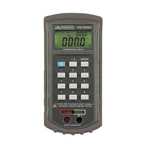
INSTRUCTION MANUAL. MZ-505C 3 OPERATING INSTRUCTIONS 3.1 Description of the controls and elements. Figure 1.- MZ-505C, front panel. 1. LCD display. Power ON/OFF button. 04/2015 Page 9... - Page 14 INSTRUCTION MANUAL. MZ-505C Scale button. Standby button and data on the backlight. Mode Selection button on. Test button frequency selection. Button Parallel or Serial selection. Resistance function selection button, Capacity and Inductance. Selection button Q/D/R. Read-button preset selection Max, Min and Average.
-
Page 15: Lcd Display Illustration
INSTRUCTION MANUAL. MZ-505C 3.2 LCD Display illustration Figure 2.- LCD Display. On AutoShutdown indicator. RS232 indicator. Record mode indicator. Δ Mode indicator on. Maximum reading indicator. Tolerance mode indicator. Minimum reading indicator. Average reading indicator. Indicator of resistance in series or parallel. - Page 16 INSTRUCTION MANUAL. MZ-505C 10. Q Quality factor indicator. 11. D Dissipation factor indicator. 12. SER Series mode indicator. 13. PAL Parallel mode indicator. 8888 Secondary display. 15. % Tolerance (percentage) indicator. Resistance (MΩ / kΩ / Ω) indicator. 16. KMΩ...
-
Page 17: How To Operate
INSTRUCTION MANUAL. MZ-505C Special indication characters shrt Indicates short connectors for calibration mode OPEN Indicates open connectors for calibration mode Indicates calibration mode. FUSE Indicates damaged or open fuse. 3.3 How to operate CAUTION Note: For achieving optimum precision for all L, C and R measurements at either the highest or lowest ranges, it is recommended to calibrate the meter before testing. -
Page 18: Capacitance Measurement
INSTRUCTION MANUAL. MZ-505C Read the display readings for inductance value and quality factor. Figure 3.- Inductance measurement 3.3.2 Capacitance measurement 1. Press [2] button to turn on the meter. 2. Press button select capacitance measurement. 3. Insert a capacitor into the component receptacle socket or connect the test clip to the component leads as required. -
Page 19: Resistance Measurement
INSTRUCTION MANUAL. MZ-505C 6. Read the display readings for capacitance value and dissipation factor. Warning To avoid electrical hazards, discharge the capacitor to be tested before measuring. Figure 4.- Capacitance measurement 3.3.3 Resistance measurement Press [2] button to turn on the meter. - Page 20 INSTRUCTION MANUAL. MZ-505C Insert a resistor into the component receptacle socket or connect the test clip to the component leads as required. Press [6] button to select testing frequency. Read the display readings for resistance value. Figure 5.- Resistance measurement.
-
Page 21: Operating Instructions
INSTRUCTION MANUAL. MZ-505C 4 OPERATING INSTRUCTIONS 4.1 Autopower down If unused for about 10 minutes, the meter will power down automatically. Press [2] button switches to resume power-on mode. When the power is down, press [2] button to turn on the meter. -
Page 22: Frequency Select
INSTRUCTION MANUAL. MZ-505C 4.2 Frequency select Set the [6] button switch to 120 Hz or 1 kHz according to the specimen to be test. Generally, the electrolytic capacitor is set to 120 Hz. Others are set to 1 kHz in general. -
Page 23: L/C/R Function Button (Only Main Indicator)
INSTRUCTION MANUAL. MZ-505C 4.5 L/C/R Function button (only main indicator) key switch the measurement parameter in sequence Q-D-R-Q..., the enunciator is indicated on LCD. When the meter is turned on, it is set to the measurement parameter selected that was in use when the meter was last turned off. -
Page 24: Min/Max Button
INSTRUCTION MANUAL. MZ-505C 4.8 MIN/MAX BUTTON Press [6] to enter the MIN/MAX/AVG mode, and stop the auto shut down function. In addition to power and hold key, the other keys cannot be activated. When the meter samples about 6 times, and then beeper will emit a sound. -
Page 25: Set
INSTRUCTION MANUAL. MZ-505C 4.9 SET 1. The [11] can only be activated only before you have not used any other functions. 2. Press [11] to enter the SET mode, and change to manual range mode automatically. 3. While in the SET function, the main display is cleared, the second display shows “SET”... - Page 26 INSTRUCTION MANUAL. MZ-505C 5. Hi/Lo Limits Settings: Press [12], LCD only shows “ ” flashing. The previous setting Hi will also appear and let user to do the modifications. When you input Lo setting value, the annunciator “ ” is flashing. The previous setting Lo will also appear and let user to do the modifications.
-
Page 27: Rel. Relative Mode (Only Main Display)
INSTRUCTION MANUAL. MZ-505C 8. Data Setting: When using the character on the name plate to input data, the previous setting will appear, and the place that waits to be entered will flash. INPUT starts from the largest digit to enter, the largest digit only 1, In that case the original setting will flash. -
Page 28: Hi/Lo Limits
INSTRUCTION MANUAL. MZ-505C The user (see “SET” in this manual can also set the relative value). When the desired relative value has been entered, press [5] key to enter the Relative mode, and press [11] key to use Relative value as a reference value. Press [5] again to exit the relative Mode. -
Page 29: Automatic Fuse Status Detection
INSTRUCTION MANUAL. MZ-505C There are 4 preset values in the TOL mode for instant use, just to press [13] again to cycle through 1%, 5%, 10%, 20% then back to the present. When entering the TOL mode, and the enunciator “... -
Page 30: Calibration
INSTRUCTION MANUAL. MZ-505C Figure 6.- Fuse detection. 4.14 Calibration The calibration process is activated automatically in certain types of measurement and according to the range, although also it is possible to be carried out manually in any range. Simply press [11] button for more twice to enter the calibration mode and calibration prompts will be displayed. -
Page 31: Low Battery Indication
INSTRUCTION MANUAL. MZ-505C Calibration prompts will be displayed automatically every time those ranges are manually or functionally selected, (e.g. REL, TOL, REC etc.), and calibration is recommended. Simply follow the open Open shrt connector ( ) or short connector (... - Page 32 INSTRUCTION MANUAL. MZ-505C Page 28 04/2015...
-
Page 33: Maintenance
INSTRUCTION MANUAL. MZ-505C 5 MAINTENANCE WARNING To avoid electrical shock, do not perform any service unless you are qualified to do so. 5.1 Service If the instrument fails to operate, to check battery and test leads, and replaces them if necessary. If the instrument still can’t work, double check operating procedure as described in this instruction manual. -
Page 34: Fuse Replacement
INSTRUCTION MANUAL. MZ-505C Figure 8.- Battery replacement 5.3 Fuse replacement The meter can self-detect if its input protective fuse is either open or damaged. In this case, the LCD will display the symbol FUSE " " and an audible beep will sounds continuously, warning the user to replace the damaged fuse to maintain the instrument operating. -
Page 35: Cleaning Recommendations
INSTRUCTION MANUAL. MZ-505C Figure 9.- Fuse replacement. 5.4 Cleaning recommendations CAUTION To clean the cover, take care the instrument is disconnected CAUTION Do not use scented hydrocarbons or chlorized solvents. Such products may attack the plastics used in the construction of the cover. - Page 36 INSTRUCTION MANUAL. MZ-505C Page 32 04/2015...
Need help?
Do you have a question about the MZ-505C and is the answer not in the manual?
Questions and answers