Table of Contents
Advertisement
Advertisement
Table of Contents

Related Manuals for Autonics PMC-HS Series


Summary of Contents for Autonics PMC-HS Series
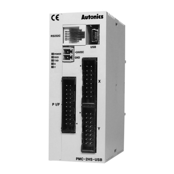
- Page 1 The invisible hand for more convenient world sensors & controllers (PMC-1HS/PMC-2HS) 1 • 2-Axis High Speed Motion Controller INSTRUCTION MANUAL 1 • 2-Axis High Speed Motion Controller Thank you very much for selecting Autonics products. For your Safety, please read the following before using.
-
Page 2: Table Of Contents
Start of operation program ������������������������������������������������������������������������������������������������������ 39 Main Screen ���������������������������������������������������������������������������������������������������������������������������� 40 Parameter/Mode Screen ��������������������������������������������������������������������������������������������������������� 44 5.3.1 Mode Tab ���������������������������������������������������������������������������������������������������������������� 44 5�3�2 Parameter Tab ��������������������������������������������������������������������������������������������������������� 45 5.3.3 Home Search Mode Tab ����������������������������������������������������������������������������������������� 46 5�4 Program Edit Screen ��������������������������������������������������������������������������������������������������������������� 47 © Copyright Reserved Autonics Co., Ltd. -
Page 3: Table Of Contents
8�1�3 CN3: Parallel I/F Connector ������������������������������������������������������������������������������������ 64 8�1�4 CN4, CN5: I/O Connector ��������������������������������������������������������������������������������������� 67 9� Serial Communication Commands ������������������������������������������������������������������������������������������������������ 69 9�1 Communication condition �������������������������������������������������������������������������������������������������������� 69 9�2 Command Cycle ���������������������������������������������������������������������������������������������������������������������� 69 9�3 Command �������������������������������������������������������������������������������������������������������������������������������� 69 © Copyright Reserved Autonics Co., Ltd. -
Page 4: Cautions For Safety
7. If a ribbon cable is used as the I/O line, connect the cable correctly and prevent from poor contact. Failure to follow this instruction may result in malfunction� 8. Note that this device is KCC certified for commercial use. Make proper applications for the product. © Copyright Reserved Autonics Co., Ltd. -
Page 5: Cautions During Use
④ Installation category II ※ The above specifications are subject to change and some models may be discontinued without notice. ※ Be sure to follow cautions written in the instruction manual and the technical descriptions (catalog, homepage). © Copyright Reserved Autonics Co., Ltd. -
Page 6: 1� Introduce
1. Introduce Product Overview PMC-HS series is a unit to determine the position or control the speed of a pulse input servo motor or a stepper motor. The built-in EEPROM can store operation parameters and maximum 64-program data per each axis. PMC-1HS is a 1-axis motion controller and divided into PMC-1HS-232 and PMC-1HS-USB models, PMC-2HS is a 2-axis motion controller and divided into PMC-2HS-232 and PMC-2HS-USB. -
Page 7: Start The Drive
The PMC-1HS/2HS is connected to a PC or a sequence controller via an USB cable or RS-232C communication cable and it can control axes by means of user's independent program� For more information, refer to "9� Serial Communication Commands" © Copyright Reserved Autonics Co., Ltd. -
Page 8: 2� Program Installation And Delete
4th Select the [Next] button� 5th Select the desired folder and click the [Next] button� 6th The progress of the installation is 7th The Installation Complete screen is displayed displayed� Click the [Close] button� © Copyright Reserved Autonics Co., Ltd. -
Page 9: Delete Of Operation Program
2. Program Installation and Delete Delete of Operation Program Delete this program with "Add/remove programs" in your Control Panel� 2nd Click the "Remove" button after selecting "PMC" on the list of the screen. © Copyright Reserved Autonics Co., Ltd. -
Page 10: Installation Of Usb Drive
Execute the "My computer → Properties (Click right mouse button) → Hardware → Device Manager". If "PMC-HS-USB Driver (Autonics Corp)" exists in "Universal Serial BUS controller" and "Autonics Serial port" exists in "Port (COM and LPT)", the USB driver was installed normally. 2.3.1 Check the starting of the operation Program When you connect the motion controller, check the operation program is run correctly�... -
Page 11: Connection Of Rs-232C
2nd Turn on the motion controller and the PC� 3rd Start the operation program by selecting the [Start] button� Click the Start → Program → Autonics → Motion Controller → PMC → PMC. 4th For initial access, the communication error message is popped up�... -
Page 12: Configuration Of The Operating Mode And System Parameters
There are Mode, Parameter and Home Search Mode tabs on the Parameter/Mode screen. Set up value for each tab to meet the system requirement� 3.1.1 Mode Mode tab is available to set Limit Stop Mode, End Pulse, etc. Only X-axis is displayed for PMC-1HS. © Copyright Reserved Autonics Co., Ltd. - Page 13 It selects High if the nALARM is activated in Open, and it selects Low in GEX. To cancel an error after error is occurred, it deactivates the nALARM and resets the controller. If the nALARM is not used, the level is configured as the Factory default. © Copyright Reserved Autonics Co., Ltd.
- Page 14 E.g.) If the drive speed, V is equal to 100kpps, the Decel (D) must be bigger than 1/40 of the Accel (A). Drive Speed Deceleration > Acceleration× 4×10 (2)As the rate of Accel and Decel is increased, PMC-1HS/PMC-2HS is accelerated so that it may be decelerated due to the shortage of pulse numbers� © Copyright Reserved Autonics Co., Ltd.
- Page 15 Program Start� Change after the program is closed on the main screen by pressing the [Stop] button� Warning When the Power On Home Search is configured as Enable, note that the personnel injury may be resulted. © Copyright Reserved Autonics Co., Ltd.
-
Page 16: Parameter
If the Speed Multiplier is set to 10 then, Acceleration value configured: A = 65,000 / (125×10) = 52 Start Speed value configured: SV = 500 / 10 = 50 Drive Speed value configured: V = 20,000 / 10 = 2,000 © Copyright Reserved Autonics Co., Ltd. - Page 17 The post timer is the waiting time to start next command after the execution of a drive command such as ABS or INC for program operation� Display Setting range Factory default Post Timer 1 1 to 65,535 Post Timer 2 1 to 65,535 Post Timer 3 1 to 65,535 1,000 © Copyright Reserved Autonics Co., Ltd.
- Page 18 Soft Ware Limit - -8,388,608 to +8,388,607 -8,388,608 The above configuration range is the value when numerator/denominator of pulse scale=1000/1000. The software limit can be configurable by setting "Soft Ware Limit" to Enable in Mode tab. © Copyright Reserved Autonics Co., Ltd.
- Page 19 (14) Pulse Scale Denominator It is the denominator value to execute actual pulse scaling provided for input position data� Display Setting range Factory default Pulse Scale Denominator 1 to 65,535 1,000 © Copyright Reserved Autonics Co., Ltd.
-
Page 20: Home Search Mode
When the home signal (nSTOP1) is deactivated, the step 2 starts. ③ The limit signal of the detected direction is activated in use. → Stop the drive and perform the same operation with ②� © Copyright Reserved Autonics Co., Ltd. - Page 21 If the signal is connected to the GEX, the drive stops evaluating that the signal is active. In case of High, the drive goes slow and stops evaluating that the opened signal is active� © Copyright Reserved Autonics Co., Ltd.
- Page 22 If - is configured, the drive pulse comes out tn the - direction of the detection direction. Position Clear When the home search ends, this mode clears the position counter� Display Selection Factory default Position Clear Disable / Enable Enable © Copyright Reserved Autonics Co., Ltd.
- Page 23 ② Its active level is opposite with the OUT command of the operation program� (10) DCC Width (μsec) This mode configures the width of the deviation counter clear pulse output. Display Selection (μsec) Factory default DCC Width (μsec) 10/20/100/200/1,000/2,000/10,000/20,000 10 Select one of 10/20/100/200/1,000/2,000/10,000/20,000 μsec. © Copyright Reserved Autonics Co., Ltd.
- Page 24 ② of the step 2 started� If it is on B point, the limit of the detection direction goes into the step 1, it starts the irregular operation ② of the step 2� Complete the process by moving to step 4 in specified direction (+) as setting value (3500 pulse). © Copyright Reserved Autonics Co., Ltd.
- Page 25 Step 4 Enable Enable Operation Step 4 Direction + direction Position Clear Enable Clear the position counter after searching home Using Limit Signal Disable No-operation DCC Enable Disable No-operation DCC Level DCC Width (μsec) © Copyright Reserved Autonics Co., Ltd.
- Page 26 If the start position of the home search is in the limit (Fig. 1, A point), step 1 is not operated and step 2 starts. It reversely moves a certain position in step 4 and ends escaping the limit� © Copyright Reserved Autonics Co., Ltd.
- Page 27 Start Speed Start Speed of trapezoid drive Home Search Low Speed Slower than the start speed of 200 pps Home Search High Speed 1,000 10,000pps Home Search Offset Required distance to escape the limit range © Copyright Reserved Autonics Co., Ltd.
- Page 28 Enable Operation (escaping the limit) Step 4 Direction + direction Clear position counter after Position Clear Enable completing home search Using Limit Signal Enable DCC Enable Disable Not used DCC Level DCC Width (μsec) © Copyright Reserved Autonics Co., Ltd.
- Page 29 3. Configuration of the Operating Mode and System Parameters © Copyright Reserved Autonics Co., Ltd.
-
Page 30: Configuration Of Operation Program
Click the [ProgramEdit] button on the main screen� The Program edit screen is displayed� For the detailed handling of the program edit screen, refer to "5�4 Program Edit Screen" This paragraph only describes each command of the program� © Copyright Reserved Autonics Co., Ltd. -
Page 31: Commands In The Operation Program
When Both register reaches after program is executed, both X and Y-axis for the register will be executed together. If executing both axis programs together after making each X and Y-axis separate program, Error will occur. In other words, Y-axis will be used as an auxiliary axis for X-axis. © Copyright Reserved Autonics Co., Ltd. - Page 32 If it is high (open), execute the next register. ● Data1: Specifies input port number. Refer to "4.1.2 I/O port numbers" for input port number. ● Data2: Specifies the register number to jump. The range is 0 to 63. © Copyright Reserved Autonics Co., Ltd.
- Page 33 Repeat 3 times Repeat 10 times Repeat 5 times RPE (end repetition) Data Repeat the execution from the repeat start command (REP) to this command. © Copyright Reserved Autonics Co., Ltd.
-
Page 34: I/O Port Numbers
Output numbers Output port No Connector Pin No Signal name Signal description Signal type XOUP0 General output X-axis 0 X-axis signal YOUT0 General output Y-axis 0 Y-axis signal PHC-1HS can not use input port 10� © Copyright Reserved Autonics Co., Ltd. -
Page 35: Drive By Parallel I/F
● During Auto Home Search, the soft limit is ignored even if it is enabled� ● For PMC-1HS, the axis specification signal is disabled. ● OFF signals of X and Y DRIVE/END are executed after OFF signal of the Home is confirmed. © Copyright Reserved Autonics Co., Ltd. -
Page 36: Index
When nDRIVE signal is ON, drive will be remained even if other input signal is OFF� The nDRIVE signal goes to the OFF status if the STROBE signal is checked in OFF status� For PMC-1HS, X and Y-axis signals are disabled. © Copyright Reserved Autonics Co., Ltd. -
Page 37: Jog
JOGX- (7) + direction of Y- axis JOGY+ (4) - direction of Y- axis JOGY- (5) Caution When the jog mode 2 is running, do not execute the Home Search by the Home (2) signal. © Copyright Reserved Autonics Co., Ltd. -
Page 38: Continuous
MODE0 (12) = ON, MODE1 (13) = ON Axis specification X (4), Y (5) = ON state of the axis to execute REGSL (6) to REGSL5 (11) Register number specification Refer to "4.2.2 Index" <Register number specification table> . © Copyright Reserved Autonics Co., Ltd. - Page 39 4. Configuration of Operation Program © Copyright Reserved Autonics Co., Ltd.
-
Page 40: 5� Drive By Pc
(3)Start the operation program by clicking the [Start] button. Click Start → Program → Autonics → Motion Controller → PMC → PMC. If the communication with the main body is normal, all data configured to the main body (Operation mode, parameters and operation program) is uploaded on the PC and the main screen is displayed. -
Page 41: Main Screen
This function selects the drive speed of JOG operation. Speed 1 to 4 means the drive 1 to 4 configured on the Parameter tab. Speed 5 means the speed configured as speed5 on the screen. The speed can be changed in driving� © Copyright Reserved Autonics Co., Ltd. - Page 42 The selection of Home Search mode or Home Search speed is configured on the parameter/mode screen� Display Operations X, Y Selects the axis to carry out the Home Search� Starts the Home Search� Stop Stops the Home Search� © Copyright Reserved Autonics Co., Ltd.
- Page 43 ● Both is configured as 1 if both of X and Y are selected or zero for others. If the current position is configured, the REG number in 'Running program (⑥)' is increased by one. © Copyright Reserved Autonics Co., Ltd.
- Page 44 (Version: ******* and Version of app: *******). ⑪ Main body reset This function is used to reset PMC-1HS/PMC-2HS main body. © Copyright Reserved Autonics Co., Ltd.
-
Page 45: Parameter/Mode Screen
Servo Alarm Enable Disable/Enable Disable Servo Alarm Level Low/High End Pulse Disable/Enable Disable Deceleration Value Accel/Decel Accel Soft Ware Limit Disable/Enable Disable Power On Home Search Start Disable/Enable Disable Power On Program Start Disable/Enable Disable © Copyright Reserved Autonics Co., Ltd. -
Page 46: Parameter Tab
End Pulse Width (msec) 1 to 65,535 (msec) Pulse Scale Numerator 1 to 65,535 1,000 Pulse Scale Denominator 1 to 65,535 1,000 ※1: When the numerator and the denominator of pulse scale are equal� © Copyright Reserved Autonics Co., Ltd. -
Page 47: Home Search Mode Tab
Step 4 Direction + / - Position Clear Disable/Enable Enable Using Limit Signal Disable/Enable Disable DCC Enable Disable/Enable Disable DCC Level 0 / 1 10, 20, 100, 200, DCC Width (μsec) 1,000, 2,000, 10,000, 20,000 © Copyright Reserved Autonics Co., Ltd. -
Page 48: Program Edit Screen
Selection of drive speed 1 to 4 Speed Other commands Not required to configure Selection of post timer 1 to 3 ABS, INC If it is unnecessary, select zero� Timer Other commands Not required to configure © Copyright Reserved Autonics Co., Ltd. - Page 49 Insert blanks to the selected line� If the last line number of the program after inserting blanks is over 63 with the numbers or more Insert Insertion of lines than 63 are deleted� In online state, the inserted program data is added to the main body� © Copyright Reserved Autonics Co., Ltd.
-
Page 50: I/O Signal Screen
Mode tab. The input signal of Parallel I/F (CN3) lights when the input signal is connected to GEX and its output signal lights when the signal is ON, which is the output transistor is ON� If you double-click the signal name, the ON/OFF output is reversed� © Copyright Reserved Autonics Co., Ltd. -
Page 51: Error Code
A value other than input range was input� the limits The online state can be changed into the offline state. To recover the online state, select the File (F) and retry the communication such as Upload → Parameter → X-axis. © Copyright Reserved Autonics Co., Ltd. -
Page 52: 6� Drive By Teaching Unit
• Adding operation mode parameter and operation program Data edit Register number • Index drive operation • Displaying the current position • JOG operation Drive handling • Home search (drive operation) • Program execution © Copyright Reserved Autonics Co., Ltd. -
Page 53: Operation Of The Data Edit
If you give the button a short press, the number increases by one� Otherwise, the number increases continuously� If ABS and INC commands were configured in the register, the short press displays a position data and the operation mode� If you press the button again, the next register is displayed� © Copyright Reserved Autonics Co., Ltd. -
Page 54: Register Composition
The teaching unit (PMC-2TU-232, sold separately) does not have the pulse scale function. All of the position data of REF00 to 63 and the parameters of REG 87, 88 and 89 become pulse values� © Copyright Reserved Autonics Co., Ltd. -
Page 55: Input Of The Operation Program
Input numbers are 4 Input a value� displayed from the right 3 0 0 of the DATA Time configuration The position data Press the [WRT] flickers twice to inform button� the completion of the registration� © Copyright Reserved Autonics Co., Ltd. - Page 56 Press the [REG] button to cancel the input and return to the previous data� Caution Input position data in pulse unit� The teaching unit (PMC-2TU-232) does not have the pulse scaling function. © Copyright Reserved Autonics Co., Ltd.
-
Page 57: Input Of Operation Mode And Parameters
"6�1�4 Input of The display flickers twice Operation Mode and Parameters" Press the [WRT] to inform the completion button� (1) Mode display'. of the registration� © Copyright Reserved Autonics Co., Ltd. - Page 58 3 Use of Limit Signal 0: Disable 1: Enable 4 DCC 0: Disable 1: Enable 5 DCC Active 0: ON Pulse 1: OFF Pulse DATA digit DCC pulse width (μsec) 1,000 2,000 10,000 20,000 © Copyright Reserved Autonics Co., Ltd.
-
Page 59: Index Drive
If you stop the operation, press the [STOP] button of each axis� Caution If the operation mode, parameter and home search mode should be configured before executing the home search� It may cause that the home search is not performed correctly� © Copyright Reserved Autonics Co., Ltd. -
Page 60: Jog Operation
X-axis or Y-axis is displayed respectively. If X/Y-axis is operating, the current on X-axis is displayed. Once the program is running, you can monitor the current position by selecting an axis by means of the [X/Y] button. © Copyright Reserved Autonics Co., Ltd. -
Page 61: Record Of The Current Position
) ) ) ! ! ABS/INC configuration 0: INC, 1: ABS Drive Speed 1, 2, 3, 4 Post Timer 0, 1, 2, 3 End P 0: OFF, 1: ON Both 0: OFF, 1: ON © Copyright Reserved Autonics Co., Ltd. -
Page 62: Product Specifications
7. Product Specifications 7. Product Specifications Dimensions 2-Ø5 (unit: mm) 35mm Din Rail connectable 35�5 7.1.1 Sold separately (teaching unit, PMC-2TU) © Copyright Reserved Autonics Co., Ltd. -
Page 63: Specifications
(approx. 96.8g) (approx. 96.9g) (approx. 100.2g) (approx. 100.4g) ※1: The weight includes packing� The weight in parenthesis is for only unit� ※The temperature or humidity mentioned in Environment indicates a non freezing or condensation� © Copyright Reserved Autonics Co., Ltd. -
Page 64: 8� Connector
8. Connector Connector Types and I/O Signal Connection Connector positions and pin numbers of PMC-HS Series is shown in the figure below. Note that you connect wires following pin number correctly. If the power connector (CN1) is connected in reverse or any current/voltage in excess of the rated current/voltage are entered to each signal, internal circuit may be broken�... -
Page 65: Cn3: Parallel I/F Connector
If the nDRIVE/END signal is used as the drive end pulse, make the Home signal in the ON state of more than 10 msec� Caution Do not make the HOME in the ON state during the JOG drive. © Copyright Reserved Autonics Co., Ltd. - Page 66 JOG mode 1, 2 Disable Continuous drive Stops the continuous drive� Stops the program drive� ※1 Program drive Stops the drive, if a drive command is running� Home search Stops during the executing of home search� © Copyright Reserved Autonics Co., Ltd.
- Page 67 Home and OFF after ending� that the end pulse is enabled is completed� ● X ERROR (X-axis error output) Y ERROR (Y-axis error output) For the control on each axis, the signal is ON if an error occur� © Copyright Reserved Autonics Co., Ltd.
-
Page 68: Cn4, Cn5: I/O Connector
OUT command (ON/OFF of output port) and OTP command (ON pulse from output port) is used for this signal. If selecting Enable for DCC output with Home Search Mode tab, it is output depending on preset logic level and pulse width after Home Search Step 3 (Z-phase search) ends. © Copyright Reserved Autonics Co., Ltd. - Page 69 This is the output power (+24VDC) to supply the power to the limit, home sensor. Configure the current at less than 100mA. The VEX power is transferred to CN3, CN4 and CN5. Configure the current at less than 300mA� © Copyright Reserved Autonics Co., Ltd.
-
Page 70: 9� Serial Communication Commands
Put the axis specification "X" in case of PMC-1HS. [Example] To drive X-axis and Y-axis in the + and - directions respectively. JOG X-Y [CR] The + direction can be omitted in the axis specification. Response: No-response © Copyright Reserved Autonics Co., Ltd. - Page 71 Format Command [Axis specification] [CR] X [CR] Put the axis specification "X" in case of PMC-1HS. [Example] • To clear X/Y-axis for 2-axis CLL XY[CR] • To clear for 1-axis CLL X[CR] Response: No-response © Copyright Reserved Autonics Co., Ltd.
- Page 72 Current speed of X-axis • For 1-axis [LF] [CR] Current speed of Y-axis The actual drive speed is the value that the setting value is multiplied by Speed Multiplier. Drive Speed = Axis speed × Speed Multiplier © Copyright Reserved Autonics Co., Ltd.
- Page 73 Setting an axis operates with arrangement. Put the axis specification "X" in PMC-1HS. [Example] • To decelerate for stop of X and Y axes in 2-axis XY [CR] • To accelerate for stop for 1-axis X [CR] Response: No-response © Copyright Reserved Autonics Co., Ltd.
- Page 74 Put the axis specification "X" in 1-axis (PMC-1HS). Response:IDC [CR] Program number It selects the speed (1 to 4). Format Command [Axis specification] [Speed selection] [CR] [CR] Put the axis specification "X" in PMC-1HS. Response: None © Copyright Reserved Autonics Co., Ltd.
- Page 75 (XIN5) MODE1 Not used Not used (YIN0) REGSL0 (YIN1) REGSL1 (YIN2) REGSL2 (YIN3) REGSL3 (YIN4) REGSL4 (YIN5) REGSL5 Power ON home search (0: Not operated 1: Operation) Power ON program (0: Not operated, 1: Operation) © Copyright Reserved Autonics Co., Ltd.
- Page 76 RST[CR] Response: No-response It reads or modifies the condition of a communication port. If the port condition is modified, reset of main body or power is required. (1)For reading Format Command [CR] SCI [CR] © Copyright Reserved Autonics Co., Ltd.
- Page 77 Put the axis specification "X" in 1-axis (PMC-1HS). [Example] • To pause the program or drive step on X/Y-axis for 2-axis. PSP XY [CR] • To pause the program or drive step for 1-axis� PSP X [CR] Response: No-response © Copyright Reserved Autonics Co., Ltd.
- Page 78 Put the axis specification "X" in 1-axis (PMC-1HS). [Example] • To run a X and Y-axis program step by step for 2-axis PST XY 00[CR] • To run a program step by step PST X 00[CR] Response: No-response © Copyright Reserved Autonics Co., Ltd.
- Page 79 [Example] To set Speed Multiplier of X-axis=100 IHS XE6,0064 [Example] To set Step 1 Enable of X-axis home search mode to Enable IHS XF1,0001 [Response] Same with the written data [Example] To set Speed Multiplier of X-axis=100 IHS XE6,0064 © Copyright Reserved Autonics Co., Ltd.
- Page 80 Command [Axis specification] [CR] EEPROM address [CR] [Example] To read home search offset of X-axis IXR X79 [Response] EEPROM address , Data (hexademical 8-digit) [CR] [Example] To set Speed Multiplier of X-axis=100 IXR X79,00000064 © Copyright Reserved Autonics Co., Ltd.
- Page 81 7D-L 7D-L FA End_Pulse_Width End Pulse width 7D-H 7D-H FB Pulse_Scale_Numerator Pulse Scale Numerator 7E-L 7E-L FC Pulse_Scale_Denominator Pulse scale denominator FE 7F-L 7F-L FE ※The Factory default of position data X00-63 and Y00-Y63 is "FFFFFFFF." © Copyright Reserved Autonics Co., Ltd.
- Page 82 MCC-CXU1-V1.2-1712US DRW170814AC...
Need help?
Do you have a question about the PMC-HS Series and is the answer not in the manual?
Questions and answers