Table of Contents
Advertisement
Advertisement
Table of Contents

Subscribe to Our Youtube Channel
Related Manuals for L-Acoustics Syva


Summary of Contents for L-Acoustics Syva
- Page 1 SYVA rigging manual (EN)
- Page 2 Document reference: Syva rigging manual (EN) version 1.1 Distribution date: June 8, 2017 © 2017 L-Acoustics. All rights reserved. No part of this publication may be reproduced or transmitted in any form or by any means without the express written consent of the...
-
Page 3: Table Of Contents
Pole-mounting Syva..........................23 Stacking Syva on Syva Low........................24 APPENDIX A: Mounting a truss clamp on Syva Wall....................25 APPENDIX B: Storing Syva Low / Syva Sub in SyvaLF Cov.................. 26 Specications..............................27 Syva specications..........................27 Syva on Syva Low specications......................29 Syva Low specications........................... -
Page 4: Safety
Respect the Working Load Limit (WLL) of third party equipment. L-Acoustics is not responsible for any rigging equipment and accessories provided by third party manufacturers. Verify that the Working Load Limit (WLL) of the suspension points, chain hoists and all additional hardware rigging accessories is respected. -
Page 5: Symbols
This symbol noties the user about instructions that must be strictly followed to ensure proper installation or operation of the product. This symbol noties the user about complementary information or optional instructions. Syva rigging manual (EN) version 1.1... -
Page 6: Welcome
This document contains essential information on rigging the system properly. As part of a continuous evolution of techniques and standards, L-Acoustics reserves the right to change the specications of its products and the content of its document without prior notice. Please check www.l-acoustics.com... -
Page 7: System Components
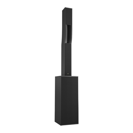
3D acoustical and mechanical modeling software Refer to the Soundvision help. Other Syva system components Other components of the system are presented in the Syva user manual along with the enclosure congurations and connection schemes. Syva rigging manual (EN) version 1.1... - Page 8 System components Rigging elements Syva Wall Syva Base Syva Pole Syva Bar CLAMP250 Syva Cov SyvaLF Cov Syva rigging manual (EN) version 1.1...
-
Page 9: Mechanical Safety
Mechanical safety Mechanical safety Flown congurations The Syva rigging system complies with 2006/42/EC: Machinery Directive. It has been designed following the guidelines of BGV-C1. 2006/42/EC: Machinery Directive species a safety factor of 4 against the rupture. The own deployments described in this manual achieve a safety factor of 5. - Page 10 Soundvision calculations are based on usual environmental conditions. A higher safety factor is recommended with factors such as extreme high or low temperatures, strong wind, prolonged exposition to salt water, etc. Always consult a rigging specialist to adopt safety practices adapted to such a situation. Syva rigging manual (EN) version 1.1...
-
Page 11: Rigging System Description
At the top, an M8 insert can be tted with a DIN-580 eye bolt to implement a secondary safety. safety point Ø M8 linking points Syva can be stacked on top of Syva Low. Four magnets and lodgings on the bottom of the enclosure ensure stability. magnet (x4) lodging (x4) - Page 12 A back plate, a top plate and a bottom plate conceal and protect the rigging elements and connectors when they are not in use. 3 N.m 3 N.m Always put the bottom plate screws back in place to avoid leaks. Remove the bottom plate to stack Syva on Syva Low or Syva Base. Syva rigging manual (EN) version 1.1...
-
Page 13: Syva Low And Syva Sub
Syva Low and Syva Sub Two anti-vibration mats are provided to ground-stack the subwoofers. Syva Low features four studs on top to ensure stability when stacking Syva. A top plate conceals them. 3 N.m Syva rigging manual (EN) version 1.1... -
Page 14: Syva Wall
Syva on Syva Wall applies a load of 350 N on the anchoring points. Syva Wall is a wall-mount for Syva. It consists in two parts, a base and a bracket: — The base is mounted on a wall or a wedge. -
Page 15: Syva Base
Syva Base Syva Base is a base plate for Syva, Syva Low and Syva Sub. It must be secured to the bottom of the enclosure and features four runners for stability. These can be removed to secure the base plate to the oor. -
Page 16: Syva Bar
Seven pickup points provide site angle settings between -10° and +5°. -10° -7.5° -5° -2° 0° +2° +5° Syva Bar and Syva can be own with the provided Ø12 mm shackle WLL 1 t or secured to a structure with CLAMP250. Syva rigging manual (EN) version 1.1... -
Page 17: Syva Cov And Syvalf Cov
Syva Cov and SyvaLF Cov Syva Cov is the reference cover for Syva. The front face (with the logo) is reinforced to protect the ns and the grill. The rear side features a pouch to store the enclosure protection plates. -
Page 18: Rigging Procedures
Secure a DIN-580 eye bolt to the dedicated insert on the enclosure to implement a secondary safety. The speakON connector is only accessible if Syva Wall is used with a wedge. Syva Wall can be mounted on a truss bridge. - Page 19 Rigging procedures Syva on Syva Wall applies a load of 350 N on the anchoring points. 2. Secure the base to the wall. Use a wedge to allow an azimut angle. Azimut angle 15° 30° 45° 60° 75° 90° Wedge depth...
- Page 20 Rigging procedures 4. Secure the Syva Wall bracket to the enclosure. 5 N.m 5. Install the enclosure on the base and secure the safety pin. CLICK! Syva rigging manual (EN) version 1.1...
- Page 21 Rigging procedures Risk of injury Secure the safety pin before changing the azimuth angle with Syva Wall. Do not touch Syva Wall while changing the azimuth angle. 6. Lift the enclosure by the bottom and rotate it to change the azimuth angle.
-
Page 22: Flying Syva
About this task Available site angles: -10° -7.5° -5° -2° 0° +2° +5° Procedure Remove the backplate from Syva and secure Syva Bar on the enclosure. Store plates and unused screws in Syva Cov. 5 N.m Syva rigging manual (EN) version 1.1... -
Page 23: Pole-Mounting Syva
17 mm wrench additional material 35 mm pole mount min number of operators Procedure 1. Remove the backplate from Syva and secure Syva Pole on Syva. Store plates and unused screws in Syva Cov. 5 N.m 150 mm / 5.9 in 2. -
Page 24: Stacking Syva On Syva Low
Procedure Risk of crushing injury Always hold Syva Base by the handle. Secure Syva Base on the bottom of Syva Low and stack Syva on top. Store plates and unused screws in Syva Cov. 3 N.m Ø... -
Page 25: Appendix A: Mounting A Truss Clamp On Syva Wall
M10 bolt with thread-locking device or sealant min number of operators About this task Syva Wall can be tted with a truss clamp to mount Syva on a truss bridge. Exploded view Follow the clamp manufacturer's recommendations on maximum torque. -
Page 26: Appendix B: Storing Syva Low / Syva Sub In Syvalf Cov
APPENDIX B: Storing Syva Low / Syva Sub in SyvaLF Cov APPENDIX B: Storing Syva Low / Syva Sub in SyvaLF Cov Procedure 1. Put the cover on the upright subwoofer with the logo on the front. 2. Tilt the subwoofer to the side using the handles. -
Page 27: SpeciCations
Description 2-way-passive enclosure: 6 x 5'' LF + 3 x 1.75'' HF diaphragm, amplied by LA4X / LA8 / LA12X Usable bandwidth (-10 dB) 87 Hz - 20 kHz ([SYVA]) Maximum SPL 137 dB ([SYVA]) Nominal directivity vertical: +5°/-21° in J shape (> 1 kHz) horizontal: 140°... - Page 28 Specications Syva dimensions 209 mm / 8.2 in 144 mm / 5.7 in 170 mm / 6.7 in Syva rigging manual (EN) version 1.1...
-
Page 29: Syva On Syva Low SpeciCations
Specications Syva on Syva Low specications Description hybrid conguration, amplied by LA4X / LA8 / LA12X Usable bandwidth (-10 dB) 40 Hz - 20 kHz ([SYVA LOW SYVA]) Maximum SPL 142 dB ([SYVA LOW SYVA]) Connectors IN: 4-point speakON Weight (net) 50 kg / 110 lb Peak level at 1 m under half space conditions using pink noise with crest factor 4 (preset specied in brackets). -
Page 30: Syva Low SpeciCations
IP55 Peak level at 1 m under half space conditions using pink noise with crest factor 4 (preset specied in brackets). Syva Low dimensions 334 mm / 13.1 in 350 mm / 13.8 in Syva rigging manual (EN) version 1.1... -
Page 31: Syva Sub SpeciCations
IP55 Peak level at 1 m under half space conditions using pink noise with crest factor 4 (preset specied in brackets). Syva Sub dimensions 350 mm / 13.8 in 334 mm / 13.1 in Syva rigging manual (EN) version 1.1... -
Page 32: Syva Wall SpeciCations
38 mm / 1.5 in 35 mm / 1.4 in Ø M6 Ø M10 Ø M6 4 mm / 0.2 in 51 mm / 2 in 41 mm / 1.6 in 65 mm / 2.6 in Syva rigging manual (EN) version 1.1... -
Page 33: Syva Base SpeciCations
Syva Base dimensions 530 mm / 20.9 in 18.5 mm / 0.7 in Ø 7 mm / 0.3 in (x4) 490 mm / 19.3 in 5 mm / 0.2 in Syva rigging manual (EN) version 1.1... -
Page 34: Syva Pole SpeciCations
Syva Pole dimensions Ø 36 mm / 1.4 in 48 mm / 1.9 in 124 mm / 4.9 in 100 mm / 3.9 in 38 mm / 1.5 in Syva rigging manual (EN) version 1.1... -
Page 35: Syva Bar SpeciCations
208 mm / 8.2 in Ø 29 mm / 1.1 in Ø 13 mm / 0.5 in (x7) 75 mm / 3 in 38 mm / 1.5 in 42 mm / 1.7 in 74 mm / 2.9 in Syva rigging manual (EN) version 1.1... - Page 36 L-Acoustics, an L-Group Company 13 rue Levacher Cintrat - 91460 Marcoussis - France +33 1 69 63 69 63 - info@l-acoustics.com www.l-acoustics.com L-Acoustics GmbH L-Acoustics Ltd. L-Acoustics Inc. Steiermärker Str. 3-5 PO. Box Adler Shine - Aston House 2645 Townsgate Road, Suite 600...
Need help?
Do you have a question about the Syva and is the answer not in the manual?
Questions and answers