Table of Contents
Advertisement
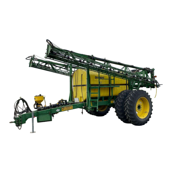
ULTIMATE NT
IMPORTANT
THE OPERATOR IS RESPONSIBLE
FOR ADJUSTING THE MACHINE SINCE
MACHINE DOES NOT COME "FIELD
READY" FROM FACTORY.
See www.summersmfg.com for latest version of all Summers Operator's Manuals
SUMMERS MANUFACTURING CO., INC.
MADDOCK, NORTH DAKOTA 58348 ................................... (701) 438-2855
DEVILS LAKE, NORTH DAKOTA 58301 ............................... (701) 662-5391
8Z1106S
Operator's
ULTRA &
SUPERSPRAYERS
WEB SITE: www.summersmfg.com
© Summers Mfg. Co., Inc. 2014
Manual
CAUTION
READ & UNDERSTAND OPERATOR'S
MANUAL BEFORE USING MACHINE.
Printed in USA
Advertisement
Table of Contents
Troubleshooting


Need help?
Do you have a question about the ULTRA and is the answer not in the manual?
Questions and answers