Table of Contents
Advertisement
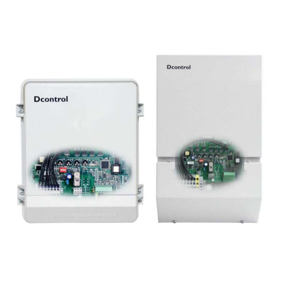
Operating instructions
Dcontrol
Type PKDT / PKDM
Controllers for voltage-regulated
3-phase motors
Applications:
• Speed controller for fans in refrigeration, air-conditioning
and clean-room engineering
• Pressure / temperature controller for refrigeration engineering
Manufacturer:
PKDT5: Software D1238A Part-No. 00162653 from version 10
PKDM5..80.: Software D1197A Part-No. 00162616 from version 07 (with two sensor inputs)
From year of construction: 2007
TBL02_54-GB 0730
ZIEHL-ABEGG AG
Heinz-Ziehl-Straße
D-74653 Künzelsau
Phone: +49 (0) 7940 16-0
Fax:
+49 (0) 7940 16-504
e-mail: info@ziehl-abegg.de
internet: http://www.ziehl-abegg.de
Part-No. 00153238-GB
Page 1 / 28
Date 0730
Advertisement
Table of Contents

Related Manuals for ZIEHL-ABEGG DControl PKDT Series


Summary of Contents for ZIEHL-ABEGG DControl PKDT Series
- Page 1 3-phase motors Applications: • Speed controller for fans in refrigeration, air-conditioning and clean-room engineering • Pressure / temperature controller for refrigeration engineering Manufacturer: ZIEHL-ABEGG AG Heinz-Ziehl-Straße D-74653 Künzelsau Phone: +49 (0) 7940 16-0 Fax: +49 (0) 7940 16-504 e-mail: info@ziehl-abegg.de internet: http://www.ziehl-abegg.de...
-
Page 2: Table Of Contents
Dcontrol Operating instructions Date 0730 Contents 1. General..........................4 2. Safety measures........................4 3. General description ......................5 3.1 Scope of applications ............................5 3.2 Technical data ..............................5 3.3 Versions ................................6 3.4 Power decrease for increased ambient temperatures ..................7 4. - Page 3 Dcontrol Operating instructions Date 0730 7.1.5 Operation with two variable output voltages (2 steps)..................16 7.2 Settings for operation as a controller ......................... 17 7.2.1 Adjusting the nominal value via potentiometer “Set” ................... 17 7.2.2 Adjusting the control range via potentiometer “Pband” ..................18 7.2.3 Min.
-
Page 4: General
Danger owing to electric current or voltage!! Important information! • The copyright for these operating instructions remains to ZIEHL-ABEGG AG, Künzelsau. • The device is constructed in accordance with the current state of technology and the recognised safety regulations. Nevertheless, use of the device is associated with dangers which may cause death or injury to users or third parties as well as damage to the system and other objects. -
Page 5: General Description
Dcontrol Operating instructions Date 0730 3. General description 3.1 Scope of applications The controlling device as described is intended for infinitely variable speed settings in voltage-regulated 3-phase motors for driving fans and pumps. 3.2 Technical data The name plate data refer to a maximum ambient temperature of 40°C. (with internal semiconductor fuses) or 50°C (without internal semiconductor fuses). -
Page 6: Versions
Dcontrol Operating instructions Date 0730 Maximum cross section for line and motor connection PKDT5 / PKDM5..20: 2.5 mm PKDM25/35 : 6 mm PKDM25/35E: 10 mm PKDM50/80 (E) : 35 mm Stepless controlled output voltage approx. 20-100 % (line voltage) Rampup time / Rampdown time for PKDM 5…35: ca. 5 sec Rampup time / Rampdown time for PKDM 50/80: ca. -
Page 7: Power Decrease For Increased Ambient Temperatures
Dcontrol Operating instructions Date 0730 3.4 Power decrease for increased ambient temperatures The unit´s maximum permissible ambient temperature is depending on version 40° C, or 50°C.Up to that temperature a load of the quoted rated current is possible. The removal of heat in the unit due to power dissipation is dependent on the ambient temperature, so the maximum load has to be reduced if the ambient temperature is higher than 40°... -
Page 8: Installation
Dcontrol Operating instructions Date 0730 4. Installation 4.1 Mounting • Assemble the device on a clean and stable base. Do not distort during assembly! Use the appropriate mounting devices for proper installation of the unit! • Do not mount equipment on vibrating base! •... -
Page 9: Electrical Connections
20 %, for 8- and 10-pole motors at approx. 15 % and higher pole motors at approx. 5 %. For the control of motors made by other manufacturers (not Ziehl-Abegg), the control characteristics and the maximum current for electronic regulation of the voltage should be enquired from the manufacturer. -
Page 10: Motor Noise
Dcontrol Operating instructions Date 0730 5.4 Motor noise Motor noise can occur when fans are controlled using electronic voltage controllers (Phase cutting = series “P...”). Such noise can be system-dependently perceived as a disturbance. This noise is relatively low for fast-running fans where the noise from the air is high. -
Page 11: Enable On / Off
Dcontrol Operating instructions Date 0730 5.8 Enable ON / OFF Enable ON / OFF (electronic disconnection) and reset after motor fault via potential free contact, terminals „D1“-„D1“. ♦ Device ON with contact closed ♦ Device OFF with contact open (“Fault“ relay K1 not released, terminals 11-14 bridged) Display for disconnection: Green LED flashes No disconnection (isolation) when turned off, in accordance with VBG4 §6. -
Page 12: Sensor Connection (Operation As A P-Controller)
Dcontrol Operating instructions Date 0730 5.11 Sensor Connection (operation as a P-controller) The signal from the sensor for detection of the actual value is connected to the terminals “E” or “E1”and “GND”, for sensor in two-wire-technology (output 4-20 mA) to terminals "E" (E1) and "24 V". Be sure to observe correct polarity. The maximum length of the connecting cable shall be 30 m (screened). -
Page 13: General Settings And Operating Elements
Dcontrol Operating instructions Date 0730 6. General settings and operating elements 6.1 Programming the operating mode (speed controller / P- controller) It is possible to use the device as a speed controller or as a P-controller. Selection of the function must first be made by setting the internal dipswitch and jumper or sliding switches (depending on version). -
Page 14: Controls
Dcontrol Operating instructions Date 0730 6.2 Controls Operation as a speed rcontroller For operation as a speed controller, the output voltage is set manually by adjusting the built-in potentiometer, by an external potentiometer or external signal (0-10 V). Setting Potentiometer Output voltage 0-100 % (switch S1-3 ON position) “SET“... -
Page 15: Settings For Operation
Dcontrol Operating instructions Date 0730 7. Settings for operation 7.1 Settings for operation as a speed controller U Motor 100 % n-min = 0 % n-max = 100 n-max n-min = 35 % n-max = 85 % The output voltage is switched off to “0” for a controller signal less than 15 % of 50 % approximately 15 % of the mains voltage... -
Page 16: Operation With Two Variable Output Voltages (2 Steps)
Dcontrol Operating instructions Date 0730 7.1.5 Operation with two variable output voltages (2 steps) Switchover between two variable output voltages for the operational mode of external control (Dipswitch S1-3 OFF position) is possible by means of "E" external potential-free contact-making. "A"... -
Page 17: Settings For Operation As A Controller
Dcontrol Operating instructions Date 0730 7.2 Settings for operation as a controller U Motor 100 % n-min = 0 % n-max = 100 % n-min = 35 % n-max = 85 % n-max The output voltage is switched off to “0” for a controller signal less than 15 % of approximately 15 % of the mains voltage 50 %... -
Page 18: Adjusting The Control Range Via Potentiometer "Pband
Dcontrol Operating instructions Date 0730 7.2.2 Adjusting the control range via potentiometer “Pband” The control response can be adjusted to the system conditions with this setting - small control range = greater amplification and shorter control times - big control range = longer control times and higher controller stability Pband ♦... -
Page 19: Setting With Pressure / Temperature Refrigerant Medium Table For Type Pkdt5 With Mbg-30I
Dcontrol Operating instructions Date 0712 7.2.5 Setting with pressure / temperature refrigerant medium table for Type PKDT5 with MBG-30I Calculation for relative pressure (differential measurement of pressure relative to ambient pressure) MBG-30I Signal R13b1 R114 R134a R142B R227 R401 R401A R401B R402 R402A... -
Page 20: Setting With Pressure / Temperature Refrigerant Medium Table For Type Pkdm5
Dcontrol Operating Instructions Date 0730 7.2.6 Setting with pressure / temperature refrigerant medium table for type PKDM5..80 with MBG-30I. Calculation for relative pressure (differential measurement of pressure relative to ambient pressure) MBG-30I Signal R13b1 R114 R134a R142B R227 R401 R401A R401B R402 R402A... -
Page 21: Minimum Airflow Rate (Minimum Air Shutdown Active / Not Active)
Dcontrol Operating instructions Date 0730 7.2.7 Minimum airflow rate (Minimum air shutdown active / not active) The minimum airflow rate can be switched "ON" or "OFF" using dipswitch. Dipswitch S1-2 OFF: Shutdown active = Without minimum airflow rate Dipswitch S1-2 ON: Shutdown not active = With minimum airflow rate (factory setting) When the setpoint is reached, the modulation is reduced to “0“... -
Page 22: Faults And Rectification Of These
Dcontrol Operating instructions Date 0730 8. Faults and rectification of these 8.1 Mains fault Function only for a connected inductive load The device is provided with a built-in phase-monitoring function for the mains supply. In the event of a mains interruption (failure of a fuse or mains phase) the unit switches off after a delay. The unit then switches on again automatically when the voltage has been restored. -
Page 23: Sensor-Signal Faults
Dcontrol Operating instructions Date 0730 8.4 Sensor-signal faults Function only for operation as a P-controller The unit is fitted with a built-in monitoring device for the sensor signal. A fault is signalled over the internal LEDs in the event of a interruption or a short circuit in the sensor conductors, or measured values that are outside of the measuring range for the unit. -
Page 24: Enclosure
Dcontrol Operating instructions Date 0730 9. Enclosure Connection diagram PKDT5 TBL02_54-GB 0730 Part-No. 00153238-GB Page 24 / 28... -
Page 25: Connection Diagram Pkdm5
Dcontrol Operating instructions Date 0730 Connection diagram PKDM5..80 TBL02_54-GB 0730 Part-No. 00153238-GB Page 25 / 28... -
Page 26: Connection Suggestion For Several Motors With Motor Protection Unit Type Stdt
Dcontrol Operating instructions Date 0730 9.3 Connection suggestion for several motors with motor protection unit type STDT • Total motor protection: Automatic cut-off by thermostat “TB” actuation ^ motor overtemperature. Button for Reset after malfunction. • Line protection: A thermal over current sensor and a magnetic short circuit releasing elements are the parts of the integral line protection. -
Page 27: Dimension Sheet
Dcontrol Operating instructions Date 0730 9.4 Dimension sheet IP 54 model range: PKDT5, PKDM5/10 (PKDM12/15) Vor Öffnen des Deckels Gerät spannungsfrei schalten! Switch off the main supply before removing the cover! IP 54 model range: PKDM20 TBL02_54-GB 0730 Part-No. 00153238-GB Page 27 / 28... - Page 28 Dcontrol Operating instructions Date 0730 IP 54 model range: PKDM25/35 (PKDM50/80) IP 20 model range: PKDM25/35E (PKDM50/80E) TBL02_54-GB 0730 Part-No. 00153238-GB Page 28 / 28...
Need help?
Do you have a question about the DControl PKDT Series and is the answer not in the manual?
Questions and answers