Sign In
Upload
Manuals
Brands
ZIEHL-ABEGG Manuals
Controller
Dcontrol PKDM20
ZIEHL-ABEGG Dcontrol PKDM20 Manuals
Manuals and User Guides for ZIEHL-ABEGG Dcontrol PKDM20. We have
2
ZIEHL-ABEGG Dcontrol PKDM20 manuals available for free PDF download: Operating Instructions Manual
ZIEHL-ABEGG Dcontrol PKDM20 Operating Instructions Manual (40 pages)
P-controller and speed controller for variable voltage 3 ~ fans
Brand:
ZIEHL-ABEGG
| Category:
Controller
| Size: 1.25 MB
Table of Contents
Table of Contents
2
1 General Notes
4
Structure of the Operating Instructions
4
Target Group
4
Exclusion of Liability
4
Copyright
4
2 Safety Instructions
4
Intended Use
4
Explanations of Symbols
5
Product Safety
5
Requirements Placed on the Personnel / Due Diligence
5
Start-Up and During Operation
5
Work on the Device
6
Modifications / Interventions in the Device
6
Operator's Obligation of Diligence
6
Employment of External Personnel
6
3 Product Overview
7
Operational Area
7
Name Plate
7
Maintenance
7
Transport
7
Storage
7
Disposal / Recycling
7
4 Mounting
8
General Notes
8
Minimum Space Requirement
8
Fastening the Device
9
Outdoor Installation
11
Installation Location for Agriculture
11
Temperature Influences During Commissioning
11
5 Electrical Installation
11
Safety Precautions
11
EMC-Compatible Installation
11
Motor Cable
11
Control Cables
11
Harmonics Current for Devices ≤ 16 a
12
Mains Connection
12
Harmonics Current and Line Impedance for Devices > 16 a and ≤ 75 a
12
Line Voltage
12
Required Quality Attributes for the Mains Voltage
12
Operating in IT-System
12
Residual-Current-Operated Protective Device
13
Motor Connection
13
Running Noise
13
Motor Protection
13
Signal Connection or Sensor Connection to Analog Inputs (Analog in 1, Analog in 2)
14
Setting Signal for Operation Speed Controller 1.01
14
Sensor Connection for Operation as P-Controller 2.01
15
Output Voltage 0 - 10 V (A1 = Analog out 1)
16
Voltage Supply for External Devices (+24V, GND)
16
Digital Inputs (D1, D2)
16
D1 = Enable (Device on / OFF)
16
D2 = Reverse Action of the Control Function
16
Relay Outputs (K1)
17
Communication
17
Networking Via MODBUS-RTU
17
RS-485 - Network Design and Interface Parameter
17
USB-Interface
18
Potential at Control Voltage Connections
18
6 Operating and Display Elements
19
7 Base Setup
20
Programming of the Desired Function (Speed Controller / P-Controller)
20
Select Operation Mode
21
Dipswitch for Operation as Speed Controller: 1.00 , 1.01
21
Dipswitch for Operation as P-Controller: 2.01 , 2.02 , 3.01 , 3.02
22
Minimum Speed Cut off DIP 5
22
For Mode Speed Controller 1.01
22
For Operation as P-Controller(from 2.01 )
22
Hardstart Function DIP 6
23
Adjusting of Cosphi for Motor
23
Adapting to SpecifiC Mains Conditions
23
Fix 60 Hz Allocation DIP 9
23
Deactivate Phase Monitoring DIP 10
23
8 Start-Up
24
Prerequisites for Commissioning
24
9 Setting for Operation
24
Speed Controller 1.00 and 1.01
24
Setting for Operation as Speed Controller
24
Operation with Two Variable Output Voltages (Two Steps)
25
Temperature Control 2.01 and 2.02
26
Setting for Operation as Temperature Controller
26
Example Temperature Control "Cooling Function" (Factory Setting)
27
Example Temperature Control "Heating Function
27
Pressure Control Condensers 3.01 and 3.02
28
Setting for Operation as Pressure Controller
28
Example Pressure Control Condensers
28
Setting with Refrigerant Medium Table
29
10 Diagnostics / Faults
30
If Controller Doesn´t Work Correctly
31
11 Enclosure
32
Technical Data
32
Max. Load Depending on Ambient Temperature
34
Connection Diagram
35
Dimensions [MM]
37
L-BAL-E143-GB 1914 Index 009 Part.-No
38
Index
39
Manufacturer Reference
40
Service Information
40
Advertisement
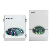
ZIEHL-ABEGG Dcontrol PKDM20 Operating Instructions Manual (28 pages)
Controllers for voltage-regulated 3-phase motors
Brand:
ZIEHL-ABEGG
| Category:
Controller
| Size: 0.45 MB
Table of Contents
Table of Contents
2
1 General
4
2 Safety Measures
4
3 General Description
5
Scope of Applications
5
Technical Data
5
Versions
6
Power Decrease for Increased Ambient Temperatures
7
4 Installation
8
Mounting
8
Minimum Space Requirement
8
Outdoor Installation
8
Installation Location for Agriculture
8
Temperature Influences During Commissioning
8
Residual-Current-Operated Protective Device
8
Potential at Control Voltage Connections
8
Employment in the IT Net
8
5 Electrical Connections
9
Mains Connection
9
Adjustment to Specific Mains Conditions
9
Motor Connection
9
Motor Feeder Cable
9
Motor Noise
10
Motor Protection
10
Special Function Only for PKDM
10
Signal Cable (Sensor Cable)
10
Enable on / off
11
Signal Connection or Sensor Connection (Analog IN1, Analog IN2)
11
External Speed Setting (Operation as a Speed Controller)
11
Inverting Setting Signal
11
Operation with Second Setting Signal at Input „E2" (Special Function Only for PKDM
11
Sensor Connection (Operation as a P-Controller)
12
Operation with a Second Sensor Signal at Input "E2" for Dual Circuit Condensers (Only for PKDM
12
Switch over Control Function at Digital in 2 (Only for Operation as P-Controller)
12
Fault Indications
12
Voltage Supply for External Equipment
12
Output Voltage (0-) 10 V (Needed Only as Required)
12
6 General Settings and Operating Elements
13
Programming the Operating Mode (Speed Controller / P- Controller)
13
Controls
14
7 Settings for Operation
15
Settings for Operation as a Speed Controller
15
Setting of Output Voltage Via Potentiometer „SET
15
Setting of Output Voltage Via External Signal or External Potentiometer
15
Min. Speed „N-Min" (Minimum Output Voltage or Basic Speed)
15
Max. Speed „N-Max" (Derating) and Cos Φ-Adjustment
15
Operation with Two Variable Output Voltages (2 Steps)
16
Settings for Operation as a Controller
17
Adjusting the Nominal Value Via Potentiometer "Set
17
Adjusting the Control Range Via Potentiometer "Pband
18
Min. Speed „N-Min" (Minimum Output Voltage or Basic Speed)
18
Max. Speed „N-Max" (Derating) and Cos Φ-Adjustment
18
Setting with Pressure / Temperature Refrigerant Medium Table for Type PKDT5 with MBG-30I
19
Setting with Pressure / Temperature Refrigerant Medium Table for Type PKDM5
20
Minimum Airflow Rate (Minimum Air Shutdown Active / Not Active)
21
Reversed Control Function (Act>Set = N+)
21
8 Faults and Rectification of These
22
Mains Fault
22
Temperature Fault
22
Motor Fault
22
Sensor-Signal Faults
23
If Controller Doesn´t Work Correctly
23
9 Enclosure
24
Connection Diagram PKDT5
24
Connection Diagram PKDM5
25
Connection Suggestion for Several Motors with Motor Protection Unit Type STDT
26
Dimension Sheet
27
Advertisement
Related Products
ZIEHL-ABEGG Dcontrol PKDM25
ZIEHL-ABEGG Dcontrol PKDM25E
ZIEHL-ABEGG PKDM20Z
ZIEHL-ABEGG PKDM25Z
ZIEHL-ABEGG Dcontrol PKDM12
ZIEHL-ABEGG Dcontrol PKDM35E
ZIEHL-ABEGG Dcontrol PKDM50
ZIEHL-ABEGG Dcontrol PKDM80E
ZIEHL-ABEGG Dcontrol PKDM80
ZIEHL-ABEGG PKDM5
ZIEHL-ABEGG Categories
Fan
Engine
DC Drives
Control Unit
Controller
More ZIEHL-ABEGG Manuals
Login
Sign In
OR
Sign in with Facebook
Sign in with Google
Upload manual
Upload from disk
Upload from URL