Table of Contents
Advertisement
We advise you to read this manual carefully, which contains all the instructions for
maintaining the appliance's aesthetic and functional qualities.
For further information on the product: www.smeg.com
Contents
4
4
5
6
6
6
6
7
8
8
9
9
10
11
13
13
14
14
17
18
18
20
22
26
26
26
28
28
29
31
33
33
38
3
Advertisement
Table of Contents

Related Manuals for Smeg SUK91CMX9


Summary of Contents for Smeg SUK91CMX9
-
Page 1: Table Of Contents
4.5 Vapor Clean 4.6 Extraordinary maintenance 5 Installation 5.1 Positioning 5.2 Electrical connection We advise you to read this manual carefully, which contains all the instructions for maintaining the appliance’s aesthetic and functional qualities. For further information on the product: www.smeg.com... -
Page 2: Instructions
Instructions 1 Instructions • Have qualified personnel carry out installation and assistance 1.1 General safety instructions interventions according to the standards in force. Risk of personal injury • Do not modify this appliance. • During use the appliance and its •... -
Page 3: Manufacturer Liability
Instructions • Never leave the appliance For this appliance unattended during cooking • Ensure that the appliance is operations where fats or oils switched off before replacing the could be released. bulb. • Never leave objects on the • Do not rest any weight or sit on cooking surface. -
Page 4: Appliance Purpose
Instructions 1.3 Appliance purpose • Deliver the appliance to the appropriate recycling centre for electrical and • This appliance is intended for cooking electronic equipment waste, or return it to food in the home environment. Every the retailer when purchasing an other use is considered improper. -
Page 5: How To Read The User Manual
Instructions 1.7 How to read the user manual This user manual uses the following reading conventions: Instructions General information on this user manual, on safety and final disposal. Description Description of the appliance and its accessories. Information on the use of the appliance and its accessories, cooking advice. -
Page 6: Description
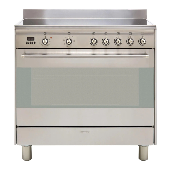
Description 2 Description 2.1 General Description 1 Upstand 6 Door 2 Cooking hob 7 Fan 3 Control panel 8 Storage compartment 4 Oven light Rack/tray support frame shelf 5 Seal... -
Page 7: Cooking Hob
Description 2.2 Cooking hob Zone Outside diameter (mm) Max. power draw (W)* Inside diameter (mm) Max. power draw (W)* 1200 2000 oval plate 2200 1400 2000 Power levels are approximate and can vary according to the pan used or the settings made. 2.3 Control panel 1 Programmer clock 2 Temperature knob... -
Page 8: Other Parts
Description 3 Indicator light 2.4 Other parts The indicator light comes on to indicate that Shelves the oven is heating up. It turns off as soon as The appliance features shelves to position it reaches the set temperature. It flashes trays and racks at different heights. -
Page 9: Available Accessories
Description 2.5 Available accessories Tray Some models are not provided with all accessories. Rack Useful for collecting fat from foods placed on the rack above. Deep tray Useful for supporting containers with food during cooking. Tray rack Useful for collecting fat from foods placed on the rack above. - Page 10 Description Rotisserie Useful for cooking chicken and all foods which require uniform cooking over their entire surface. The accessories intended to come into contact with food are made of materials that comply with the provisions of current legislation. Supplied and optional accessories can be requested to Authorised Assistance Centres.
-
Page 11: Use
3 Use Improper use Risk of damage to surfaces 3.1 Instructions High temperature inside the oven • Do not cover the bottom of the oven during use cavity with aluminium or tin foil sheets. Danger of burns • If you wish to use greaseproof paper, place it so that it will not interfere with the •... -
Page 12: First Use
Oven cavity High temperature inside the oven during use 4. Heat the empty oven at the maximum temperature to burn off any residues left Danger of fire or explosion by the manufacturing process. • Do not spray any spray products near the appliance. - Page 13 Racks and trays Rotisserie Racks and trays have to be inserted into the 1. Insert the 4 supplied bushings in the 4 side guides until they come to a complete corner holes of the deep tray and screw stop. them onto the ring nuts with a suitable tool (such as a screwdriver).
- Page 14 3. Prepare the rotisserie rod with the food 5. Place the tray on the first runner (see using the clip forks provided. The clip “General Description”). forks can be tightened using the 6. Insert the tip of the rod in the rotisserie fastening screws.
-
Page 15: Using The Hob
8. When cooking is complete, remove the Switching on the cooking zones tray with the rotisserie. The appliance has cooking zones of 9. Screw on the handle provided so that different diameters and power levels. you can handle the rotisserie rod more Their positions and the edges of the easily. -
Page 16: Using The Storage Compartment
Practical advice for using the hob 3.5 Using the storage compartment The storage compartment is at the bottom of • The diameter of the base of the pan must the cooker. To open it, pull the handle correspond to the diameter of the towards you. - Page 17 Functions list Grill The heat coming from the grill Static element gives perfect grilling results As the heat comes from above and above all for thin and medium below at the same time, this system thickness meat and, in combination is particularly suitable for certain with the rotisserie (where fitted), types of food.
-
Page 18: Cooking Advice
3.7 Cooking advice Fan with circulaire The combination of the fan and the General advice circulaire heating element • Use a fan assisted function to achieve (incorporated in the rear of the consistent cooking at several levels. oven) allows you to cook different •... - Page 19 • With the Grill function, we recommend Advice for defrosting and proving that you turn the temperature knob to the • Place frozen foods without their maximum value near the symbol packaging in a lidless container on the first shelf of the oven. optimise cooking.
-
Page 20: Programmer Clock
3.8 Programmer clock Setting the time If the time is not set, the oven will not switch on. On the first use, or after a power failure, the digits will be flashing on the appliance’s display. 1. Press the keys at the same time. - Page 21 Timed cooking 6. Press the keys at the same time to reset the programmer clock. Timed cooking is the function which allows a cooking operation to be started and then ended after It is not possible to set a cooking a specific length of time set by the time of more than 10 hours.
- Page 22 Minute minder timer 3. Use the key to set the required minutes. The minute minder timer does not stop the cooking operation but 4. Wait approx. 5 seconds without pressing rather informs the user when the set any key in order for the function to time has run out.
- Page 23 Cooking information table Runner Weight Temperature Food Function position from Time (minutes) (Kg) (°C) the bottom Lasagne 3 - 4 Static 220 - 230 45 - 50 Pasta bake 3 - 4 Static 220 - 230 45 - 50 Roast veal Turbo/Fan assisted 180 - 190 90 - 100...
-
Page 24: Cleaning And Maintenance
Cleaning and maintenance 4 Cleaning and maintenance Cleaning the glass ceramic hob Smudges from aluminium-based pans can 4.1 Instructions be easily cleaned off with a cloth dampened in vinegar. Improper use After cooking, remove any burnt residues; Risk of damage to surfaces rinse with water and dry thoroughly with a clean cloth. - Page 25 Cleaning and maintenance Weekly cleaning Cleaning the oven cavity Clean and maintain the hob once a week In order to keep your oven in the best using an ordinary glass ceramic cleaning possible condition, clean it regularly after product. Always follow the manufacturer’s letting it cool down.
-
Page 26: Removing The Door
Cleaning and maintenance 4.3 Removing the door 3. To reassemble the door, put the hinges in the relevant slots in the oven, making sure For easier cleaning, the door can be that grooved sections A are resting removed and placed on a canvas. completely in the slots. -
Page 27: Vapor Clean
Cleaning and maintenance 4.5 Vapor Clean Removing the rack/tray support frames Removing the rack/tray support frames Vapor Clean is an assisted enables the sides to be cleaned more cleaning procedure which easily. facilitates the removal of dirt. To remove the rack/tray support frames: Thanks to this process, it is possible •... - Page 28 Cleaning and maintenance • Pour approximately 40 cc of water into Vapor Clean setting the tray. Make sure it does not overflow 1. Turn the function knob to the symbol out of the cavity. the temperature knob to the symbol 2.
-
Page 29: Extraordinary Maintenance
Cleaning and maintenance 4.6 Extraordinary maintenance End of the Vapor Clean cycle 4. Open the door and wipe away the less Installing and removing the seal stubborn dirt with a microfibre cloth. To remove the seal: 5. Use an anti-scratch sponge with brass •... - Page 30 Cleaning and maintenance 4. Slide out and remove the light bulb. Replacing the internal light bulb Live parts Danger of electrocution • Unplug the appliance. The oven is fitted with a 40W light bulb. Do not touch the halogen lamp directly with your fingers, but wrap 1.
-
Page 31: Installation
Installation 5 Installation General information This appliance may be installed next to 5.1 Positioning walls, one of which must be higher than the worktop, at a minimum distance of 50 mm Heavy appliance from the side of the appliance, as shown in Crushing hazard figures A and C relative to the installation classes. - Page 32 Installation Positioning and levelling Heavy appliance Risk of damage to the appliance • Insert the front feet first and then the rear ones. • After making the gas and electrical connections, screw on the four feet supplied with the appliance. B - Class 2 subclass 1 (Built-in appliance) The appliance must sit level on the floor to...
- Page 33 Installation 3. Assemble the fastening bracket. Fastening to the wall The anti-tip devices must be installed in order to prevent the appliance tipping over. 1. Screw the wall fastening plate to the rear of the appliance. 4. Align the base of the hook on the fastening bracket with the base of the slot on the wall fastening plate.
- Page 34 Installation 5. Align the base of the fastening bracket 7. Move the bracket onto the wall and with the ground and tighten the screws to mark the position of the holes to be fix the measurements. drilled in the wall. 6.
- Page 35 Installation Wall fixing Assembling the upstand 1. Attach the chain to the cooker The upstand provided is an 2. Stretch out the chain attached to the integral part of the product. It must cooker horizontally so that the other end be fastened to the appliance prior touches the wall.
-
Page 36: Electrical Connection
Installation 5.2 Electrical connection • 380-415 V 2N~ Power voltage Danger of electrocution • Have the electrical connection 4 x 4mm² four-core cable. performed by authorised technical • 380-415 V 3N~ personnel. • Use personal protective equipment. • The appliance must be connected to earth in compliance with electrical system safety standards.
Need help?
Do you have a question about the SUK91CMX9 and is the answer not in the manual?
Questions and answers