Table of Contents
Advertisement
TRANSLATION OF THE ORIGINAL INSTRUCTIONS
We advise you to read this manual carefully, as it contains all the instructions for maintaining
the appliance's aesthetic and functional qualities.
For further information on the product: www.smeg.com
Contents
56
56
60
60
61
61
61
62
63
63
64
65
66
67
69
69
70
70
71
72
73
77
78
84
84
84
85
87
89
90
93
93
101
104
106
55
Advertisement
Table of Contents

Related Manuals for Smeg TR103BL


Summary of Contents for Smeg TR103BL
-
Page 1: Table Of Contents
5.3 Electrical connection 5.4 Instructions for the installer TRANSLATION OF THE ORIGINAL INSTRUCTIONS We advise you to read this manual carefully, as it contains all the instructions for maintaining the appliance’s aesthetic and functional qualities. For further information on the product: www.smeg.com... -
Page 2: Instructions
Instructions 1 Instructions • Keep children under the age of eight at a safe distance unless they 1.1 General safety instructions are constantly supervised. Risk of personal injury • Keep children under the age of 8 away from the appliance when it •... - Page 3 Instructions • Cooking process should always • Do not use aerosols in the vicinity be kept under control. A short of this appliance whilst it is in use. cooking process must be • Switch off the appliance after use. continuously surveyed. •...
- Page 4 Instructions Risk of damaging the appliance • Do not spray any spray products near the oven. • Do not use abrasive or corrosive • Do not use plastic cookware or detergents (e.g. scouring containers for cooking. powders, stain removers and metallic sponges) on glass parts.
- Page 5 Instructions • If any liquid does boil over or spill, • Never use the oven door to lever remove the excess from the hob. the appliance into place when fitting. • Take care not to spill acid substances such as lemon juice or •...
-
Page 6: Appliance Purpose
Instructions • The hoses should not come into For this appliance contact with moving parts and • Ensure that the appliance is should not be crushed in any way. switched off before replacing the • If required, use a pressure bulb. -
Page 7: This User Manual
Instructions 1.4 This user manual • Deliver the appliance to the appropriate recycling centre for electrical and This user manual is an integral part of the electronic equipment waste, or return it to appliance and must therefore be kept in its the retailer when purchasing an entirety and within the user’s reach for the equivalent product, on a one for one... -
Page 8: How To Read The User Manual
Instructions 1.7 How to read the user manual This user manual uses the following reading conventions: Instructions General information on this user manual, on safety and final disposal. Description Description of the appliance and its accessories. Information on the use of the appliance and its accessories. -
Page 9: Description
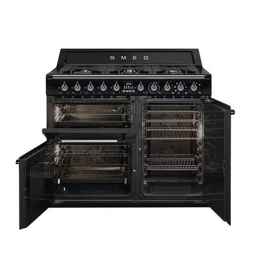
Description 2 Description 2.1 General Description 1 Upstand 7 Multifunction oven door 2 Cooking hob 8 Multifunction oven light 3 Control panel 9 Multifunction oven fan 10 Multifunction oven seal Rack/tray support frames 11 Vertical oven seal 4 Auxiliary oven light 12 Vertical oven light 5 Auxiliary oven seal 13 Vertical oven door... -
Page 10: Control Panel
Description 2.2 Control panel 1 Hob burner knobs 4 Auxiliary oven variable grill indicator light Used for lighting and adjusting the hob burners. The indicator light comes on to indicate that the auxiliary oven is heating up. It turns off Press and turn the knobs anti-clockwise to as soon as it reaches the set temperature. -
Page 11: Cooking Hob
Description 7 Multifunction oven function knob 8 Vertical oven indicator light The oven’s various functions are suitable for The indicator light comes on to indicate that different cooking modes. After selecting the the oven is heating up. It turns off as soon as required function, set the cooking it reaches the set temperature. -
Page 12: Other Parts
Description 2.4 Other parts Interior lighting The internal light of the appliance comes on Shelves when any function is started: The appliance features shelves to position • Multifunction oven: turn the function trays and racks at different heights. The knob to any function. insertion heights are indicated from the •... -
Page 13: Available Accessories
Description 2.5 Available accessories Tray rack Rack To be placed over the top of the oven tray; for cooking foods which may drip. Deep tray Used for supporting containers with food during cooking. Useful for collecting fat from foods placed on the rack above and for cooking pies, pizzas and baked desserts. - Page 14 Description Plate rack Some models are not provided with all accessories. The accessories intended to come into contact with food are made of materials that comply with the provisions of current legislation. To be used for warming plates. Supplied and optional accessories Ring reducer can be requested to Authorised Service Centres.
-
Page 15: Use
3 Use Improper use Risk of damage to surfaces 3.1 Instructions • Do not cover the bottom of the oven High temperature inside the oven cavity with aluminium or tin foil sheets. during use • If you wish to use greaseproof paper, Danger of burns place it so that it will not interfere with the •... -
Page 16: Precautions
Malfunctions High temperature inside the oven during use Any of the following indicate a malfunction and you should contact a service centre. Danger of fire or explosion • Yellowing of the burner plate. • Do not spray any spray products near •... -
Page 17: Using The Accessories
3.4 Using the accessories Tray rack The tray rack has to be inserted into the tray. Racks and trays In this way fat can be collected separately Racks and trays have to be inserted into the from the food which is being cooked. side guides until they come to a complete stop. -
Page 18: Using The Hob
Plate rack 3.5 Using the hob 1. Insert the plate rack without plates in the All the appliance’s control and monitoring first shelf of the vertical oven cavity. devices are located together on the front panel. The burner controlled by each knob 2. -
Page 19: Using The Ovens
3.6 Using the ovens Correct positioning of the flame- spreader crowns and burner caps Opening and closing the doors of the Before lighting the hob burners, make sure multifunction/vertical ovens that the flame-spreader crowns are The multifunction and vertical ovens are correctly positioned in their seats with their equipped with a swing door. - Page 20 Switching on the multifunction oven Multifunction oven functions Ensure that the programmer clock shows the cooking duration symbol , otherwise it will not Static be possible to turn on the oven. As the heat comes from above and below at the same time, this system Press the keys at the is particularly suitable for certain...
- Page 21 Grill Fan with circulaire The heat coming from the grill The combination of the fan and the element gives perfect grilling results circulaire heating element above all for thin and medium (incorporated in the rear of the thickness meat and allows you to oven) allows you to cook different give the food an even browning at foods on several levels, as long as...
- Page 22 Switching on the auxiliary oven Switching on the vertical oven To switch on the auxiliary oven: To switch on the vertical oven: • Select the temperature using the variable • Turn the knob clockwise to select the grill knob. The temperature ranges required temperature between 50 °C indicatively from a minimum of 50 °C and 245 °C.
-
Page 23: Cooking Advice
3.7 Cooking advice Advice for cooking desserts/pastries and biscuits General advice • Use dark metal moulds: They help to • Use a fan assisted function to achieve absorb the heat better. consistent cooking at several levels. • The temperature and the cooking time •... -
Page 24: Programmer Clock
• To defrost meat, use the rack placed on 3.8 Programmer clock the second level and a tray on the first level. In this way, the liquid from the defrosting food drains away from the food. • Bread and fruit, if divided into pieces, will take the same amount of time to defrost, regardless of the total weight and quantity. - Page 25 Timed cooking Setting the time Timed cooking is the function If the time is not set, the oven will which allows a cooking operation not switch on. to be started and then ended after a specific length of time set by the On the first use, or after a power failure, the user.
- Page 26 5. To turn off the buzzer just press any key Programmed cooking of the programmer clock. Programmed cooking is the 6. Press the keys at the same function which allows a cooking operation to be started at a set time to reset the programmer clock. time and then ended after a specific length of time set by the It is not possible to set a cooking...
- Page 27 6. To turn off the buzzer just press any key Minute minder timer of the programmer clock. The minute minder timer does not 7. Press the keys at the same stop the cooking operation but rather informs the user when the set time to reset the programmer clock.
- Page 28 Multifunction oven cooking information table Weight Temperature Time Food Function Level (Kg) (°C) (minutes) Lasagne 3 - 4 Static 220 - 230 45 - 50 Pasta bake 3 - 4 Static 220 - 230 45 - 50 Roasted veal Turbo/Circulaire 180 - 190 90 - 100 Pork loin...
- Page 29 Auxiliary oven cooking information table Weight Temperature Time Food Function Level (Kg) (°C) (minutes) Sausages Grill 13 - 15 surface surface Pork chops Grill Spare ribs Grill Bacon Grill Pork fillet Grill Beef fillet Grill The times indicated in the table do not include preheating times and are provided only as a guide. Vertical oven cooking information table Weight Temperature...
-
Page 30: Cleaning And Maintenance
Cleaning and maintenance 4 Cleaning and maintenance 4.2 Cleaning the hob To keep the surfaces in good condition, 4.1 Instructions they should be cleaned regularly after use. Let them cool first. Improper use 1. Pour some non-abrasive detergent on a Risk of damage to surfaces damp cloth and wipe the surface. -
Page 31: Cleaning The Doors
Cleaning and maintenance 4.3 Cleaning the doors Cleaning the grids, flame-spreader crowns and burner caps The door glazing should always be kept thoroughly clean. Use absorbent kitchen 1. Remove the components from the hob. roll. In case of stubborn dirt, wash with a 2. - Page 32 Cleaning and maintenance 2. Grasp the door on both sides with both Removing the inside glass panels (auxiliary oven only) hands, lift it forming an angle of around 30° and remove it. For easier cleaning the internal glazing panes of the door can be removed. 1.
-
Page 33: Cleaning The Oven Cavities
Cleaning and maintenance 4.4 Cleaning the oven cavities 4. Clean the external glazing pane and the panes removed previously. Use For the best oven upkeep, clean it regularly absorbent kitchen roll. In case of after having allowed it to cool. stubborn dirt, wash with a damp sponge Avoid letting food residue dry inside the and neutral detergent. - Page 34 Cleaning and maintenance Removing racks/trays support frames Cleaning the upper part (multifunction and auxiliary ovens only) Removing the guide frames enables the sides to be cleaned more easily. This High temperature inside the oven operation should be performed each time during use the automatic cleaning cycle is used (on Danger of burns...
-
Page 35: Vapor Clean (Multifunction Oven Only)
Cleaning and maintenance 4.5 Vapor Clean • Pour approx. 40 cc of water onto the (multifunction oven floor of the oven. Make sure it does not only) overflow out of the cavity. Vapor Clean is an assisted cleaning procedure which facilitates the removal of dirt. -
Page 36: Extraordinary Maintenance
Cleaning and maintenance Vapor Clean cycle setting 4.6 Extraordinary maintenance 1. Turn the function knob to the symbol Installing and removing the seal and the temperature knob to the symbol To remove the seal: • Unhook the clips in the 4 corners then pull the seal outwards. - Page 37 Cleaning and maintenance 4. Slide out and remove the light bulb. Replacing the internal light bulb Live parts Danger of electrocution • Unplug the appliance. The oven is fitted with a 40W light bulb. Do not touch the halogen light bulb directly with your fingers, but 1.
- Page 38 Cleaning and maintenance What to do if... The display is completely off: • Check the mains power supply. The appliance does not work: • Check that any circuit breaker/switch • The switch is defective: check the fuse upstream of the appliance power supply box and check that the switch is in order.
-
Page 39: Installation
Installation 5 Installation Connection with a rubber hose Verify that all following conditions are met: 5.1 Gas connection • the hose is fixed to the hose connection with safety clamps; Gas leak • no part of the hose is in contact with hot Danger of explosion walls (max. - Page 40 Installation Make the connection to the gas mains Connection with a steel hose using a rubber hose whose specifications Make the connection to the gas mains comply with current standards (verify that using a continuous wall steel hose whose the reference standard is stamped on the specifications comply with the applicable hose).
- Page 41 Installation Connection with a steel hose with conical Room ventilation fitting The appliance should be installed in rooms Make the connection to the gas mains that have a permanent air supply in using a continuous wall steel hose whose accordance with the standards in force. The specifications comply with the applicable room where the appliance is installed must standard.
- Page 42 Installation When the job is complete, the installer must Adaptation to different types of gas issue a certificate of conformity. In case of operation with other types of gas, the burner nozzles must be changed and the minimum flame adjusted on the gas cocks.
- Page 43 Installation Adjusting the minimum setting for natural Lubricating the gas cocks or town gas Over time the gas cocks may become Light the burner and turn it to the minimum difficult to turn and get blocked. Clean them position. Extract the gas cock knob and turn internally and replace the lubrication the adjustment screw next to the tap rod grease.
- Page 44 Installation Gas types and Countries Gas types IT GB-IE FR-BE DE RU DK 1 Natural Gas G20 20 mbar • • • • • • • • • G20/25 20/25 mbar • 2 Natural Gas G20 25 mbar • 3 Natural Gas G25 25 mbar •...
- Page 45 Installation Burner and nozzle characteristics tables 1 Natural Gas G20 UR2 int + ext Rated heating capacity (kW) Nozzle diameter (1/100 mm) 75 + 135 Pre-chamber (printed on nozzle) (H1) + (H3) Reduced flow rate (W) 1900 2 Natural Gas G20 UR2 int + ext Rated heating capacity (kW) Nozzle diameter (1/100 mm)
- Page 46 Installation 8 LPG G30/31 UR2 int + ext Rated heating capacity (kW) Nozzle diameter (1/100 mm) 46 + 91 Pre-chamber (printed on nozzle) Reduced flow rate (W) 1900 Rated flow rate G30 (g/h) Rated flow rate G31 (g/h) 9 LPG G30/31 UR2 int + ext Rated heating capacity (kW) Nozzle diameter (1/100 mm)
-
Page 47: Positioning
Installation 5.2 Positioning Dimensions Heavy appliance Crushing hazard • Position the appliance into the cabinet cutout with the help of a second person. Pressure on the door Risk of damage to the appliance • Never use the oven door to lever the 1000 mm appliance into place when fitting. - Page 48 Installation General information This appliance may be installed next to walls, one of which must be higher than the worktop, at a minimum distance of 50 mm from the side of the appliance, as shown in figures A and C relative to the installation classes.
- Page 49 Installation Positioning and levelling Mounting the toe skirt Heavy appliance The toe skirt provided is an integral part of the product; it must be Risk of damage to the appliance fastened to the appliance prior to installation. • Insert the front feet first and then the rear ones.
-
Page 50: Electrical Connection
Installation 5.3 Electrical connection Assembling the upstand The upstand provided is an Power voltage integral part of the product; it must Danger of electrocution be fastened to the appliance prior to installation. • Have the electrical connection performed by authorised persons. The upstand must always be positioned and •... - Page 51 Installation The appliance can work in the following modes: The values indicated above refer • 220-240 V 1N~ to the cross-section of the internal lead. The aforementioned power cables are sized taking into account the 3 x 6 mm² three-pole cable. coincidence factor (in compliance with standard EN 60335-2-6).
-
Page 52: Instructions For The Installer
Installation 5.4 Instructions for the installer • The plug must be accessible after installation. Do not bend or trap the power cable. • The appliance must be installed according to the installation diagrams. • Do not try to unscrew or force the threaded elbow of the fitting.
Need help?
Do you have a question about the TR103BL and is the answer not in the manual?
Questions and answers
Oven door . I need to renew plastic surround