Flybox Omnia57 Series Installation And User Manual
Fuel comp
Hide thumbs
Also See for Omnia57 Series:

Related Manuals for Flybox Omnia57 Series


Summary of Contents for Flybox Omnia57 Series
- Page 1 FLYBOX ® ® Fuel Comp Omnia57 Fuel Comp Installation and User Manual, (Omnia57 family) Safety Instructions and Warning Booklet Rev. 1.0...
- Page 2 Installation and User Manual, Safety Instructions and Warning Booklet This product is not TSO’d and cannot be installed into traditional FAA Part 23 and similarly Type-Certificate Aircraft Document A2019FUEL COMP Revision#1.0, 02/2019 For firmware version 1.0...
- Page 3 SECTIONS INTRODUCTION IMPORTANT NOTICE AND WARNINGS INDEX OMNIA57 FAMILY SYSTEM OVERVIEW MECHANICAL INSTALLATION ELECTRICAL INSTALLATION INSTRUMENT SETTINGS OPERATING INSTRUCTIONS TECHNICAL SPECIFICATIONS WARRANTY DISCLAIMER...
- Page 4 Examples of different screens...
- Page 5 FLYBOX ® Introduction Thank you for purchasing a Flybox® Omnia57 instrument. Our intent in developing the Omnia57 instrument family was to create a light and compact product, powerful and easy to install and use. The Omnia57 instrument family is equipped with a...
- Page 6 FLYBOX ® Important notices & warnings Symbols used in the Installation and User Manual, Safety Instructions and Warning Booklet NOTE: Used to highlight important information. CAUTION: Used to warn the user, it indicates a potentially hazardous situation or improper use of the product.
- Page 7 FLYBOX ® Important notices & warnings WARNING: These instructions must be provided to users before use, and retained for ready reference by the user. The user must read, understand (or have explained) and heed all instructions and warnings supplied with this product and with those products intended for use in association with it.
- Page 8 FLYBOX ® Important notices & warnings WARNING: This device is operated through a software which from time to time can be updated and/or subject to change. Please, always refer to the Installation and User Manual, Safety Instructions and Warning Booklet for the last updated version of the software available at www.flyboxavionics.it...
- Page 9 Installation and user Manual, Safety Instructions and Warning Booklet, do not install this instrument in his aircraft. NOTE: Flybox Avionics reserves the right to change or improve its products as well as terms, conditions, and notices under which their products are offered without prior notice.
-
Page 10: Table Of Contents
FLYBOX ® Index INDEX SECTION 1 - Omnia57 Family System overview..………… 1.1 - Construction Features …….…………………………..…. 1.2 - Ergonomics………...…...………….……………………. 1.3 - Interconnection Ability ………...…...…………..……….. 1.4 - Easy Software Update ………...…...………….…………. 1.5 - Easy Datalog Saving ………...…...………….…………… 1.6 - Interfaces ……..…...…...………….………………………... - Page 11 FLYBOX ® Index 4.5 - Fuel Computer Submenu……………………….………… 4.5.1 - K-Factor Calibration……….……….…………………… 26 4.5.2 - Fuel Pressure Submenu.….…….…….…………….…… 28 4.6 - Backlight Submenu….………….………………………… 32 SECTION 5 - Operating Instructions……….…………………… 35 5.1 - Firmware Upgrade..……………..…..….….…….………. 5.2 - Backup/Restore……………….…..…….………….….…. 5.3 - Use Of The Instrument……….…….…..…….……………. 40 5.4 - Logger…..……….
-
Page 12: Section 1 - Omnia57 Family System Overview
FLYBOX ® Omnia57 Family System Overview OMNIA57 FAMILY SYSTEM OVERVIEW The Omnia57 instrument family has many innovative features, common to all models as described below. 1.1 CONSTRUCTION FEATURES Omnia57 instrument family is built from solid aluminum alloy, CNC milled and powder coated to last a long time over the years always showing a new appearance. -
Page 13: Interconnection Ability
FLYBOX ® Omnia57 Family System Overview 1.3 INTERCONNECTION ABILITY All the instruments of the Omnia57 family can be connected together to form a communication network, making some data exchange operations simpler. The software update of a Omnia57 instrument connected in group takes place through the CAN bus communication with the instrument that has the USB pen drive connected. -
Page 14: Easy Software Update
1.4 EASY SOFTWARE UPDATE The user can download any new firmware, when available, from Flybox website, connect a USB pen drive to the instrument and freely update it with the last features. With one USB connection only, it will be possible to update every instrument installed in the panel. -
Page 15: Interfaces
2 separate CAN BUS: they can be used to connect the Omnia57 instruments together, to interface them with other Flybox instruments or with external devices like Engines ECUs or new devices that will be possibly developed in the future. -
Page 16: Section 2 - Mechanical Installation
FLYBOX ® Mechanical installation MECHANICAL INSTALLATION 2.1 MECHANICAL DIMENSIONS The Omnia57 Fuel Comp instrument fits in a standard 2 ¼” (57 mm) panel cutout; it's recommended to choose a position that permits optimal display visibility. It's furnished with four M4 screws to install it to the panel, if... - Page 17 FLYBOX ® Mechanical installation NOTE: For an installation without interference, consider making a hole of at least 57.5 mm diameter Omnia57 Fuel Comp Installation and User Manual, Safety Instructions and Warning Booklet Rev. 1.0...
-
Page 18: Fuel Flow Sensors Installation
Omnia57 Fuel Comp accepts all flow meters as long as they meet the characteristics listed in the technical specifications, see pag 48. The standard one supplied from Flybox is the code 503030 EI FT-60 (RED-CUBE). To install the fuel flow sensors, follow the manufacturer's instructions included in the sensor package, together with the general recommendations below. - Page 19 FLYBOX ® Mechanical installation ● Install the sensor with the wires pointing up. ● Respect the IN and OUT port labelled on the sensor body. ● Do not install the sensor close to high temperature objects like the exaust system or others and if needed protect the sensor with firesleeve material.
- Page 20 FLYBOX ® Mechanical installation Example of 1 Fuel Flow Transducer for a carburated engine. CAUTION: your installation may be different. Omnia57 Fuel Comp Installation and User Manual, Safety Instructions and Warning Booklet Rev. 1.0...
- Page 21 FLYBOX ® Mechanical installation Example of 2 Fuel Flow transducers for a differential measurement. CAUTION: your installation may be different. Omnia57 Fuel Comp Installation and User Manual, Safety Instructions and Warning Booklet Rev. 1.0...
-
Page 22: Section 3 - Electrical Installation
Molex P/N 43025-0200 (2 pole housing) Molex P/N 43025-2200 (22 pole housing) Molex P/N 43030-0007 (female crimp terminal) The terminals can be crimped with: - Flybox Professional Crimping Tool cod. 603000 - Molex tool P/N 63819-0000 Omnia57 Fuel Comp Installation and User Manual, Safety Instructions and Warning Booklet Rev. -
Page 23: 22 Pole Female Connector Wiring
Green Blue Ambient light sensor Light PIN 14 + 5V OUT sensor Flybox ambient light sensor code:105800 (sold separately) SPST switch, its use will be implemented in future updates External switch PIN 15 Fuel Pressure Input Fuel Flow 1 Input... -
Page 24: 22 Pole Connector Table
FLYBOX ® Electrical installation 3.3 - (22 POLE) CONNECTOR TABLE Signal +V Main supply, 10-30Vdc, with a proper breaker Vout for sensors, it delivers the same voltage supplied on the Pin 1, short circuit protected and limited to 500mA 5V out for sensor, short circuit protected... -
Page 25: Sensors Electrical Connections
FLYBOX ® Electrical installation 3.4 SENSORS ELECTRICAL CONNECTIONS FLYBOX Optional Fuel Pressure Sensor Flybox code: 601040 ( sold separately) (see NOTE 1) + Vout for sensors Brown White To Omnia57 Fuel Pressure Input Green FLYBOX Optional Fuel Flow Sensor Flybox code: 503030 (sold separately) -
Page 26: Can Bus Connection Wiring
Each end must be terminated with a 120 ohm resistor, Flybox code 105810. Up to 16 Omnia57 can be connected together through CAN 1 bus. Ready-made termination resistors and wiring for connecting several Omnia57 together are available in different lengths: 25cm, 50cm, 100cm. -
Page 27: Can Bus Connector Tables
FLYBOX ® Electrical installation 3.6 - (2 POLE) CAN BUS CONNECTOR TABLES Signal CAN 1 H Internally connected with the Pin 1-CAN 1 H (Lower connector) CAN 1 L Internally connected with the Pin 2-CAN 1 L (Lower connector) 2 Pole CAN 1 Lower Connector... -
Page 28: Section 4 - Instrument Settings
FLYBOX ® Instrument settings INSTRUMENT SETTINGS 4.1 MINIMUM SETTINGS BEFORE FIRST USE CAUTION: Before using the Omnia57 Fuel Comp in flight for the first time, you must set at least the following parameters (as explained in the instructions on the following pages): ●... -
Page 29: Panel Indicators And Commands
FLYBOX ® Instrument settings 4.2 PANEL INDICATORS AND COMMANDS 57 mm (2-1/4”) aluminium enclosure 320X240 pixels, high brightness, readable, color M4 screws Knob with pushbutton The knob can be rotated to select the functions and increment or decrement the values while pressing it to confirm. -
Page 30: Setup Menu Navigation
FLYBOX ® Instrument settings 4.3 SETUP MENU NAVIGATION Navigation through the menus is very simple and fast using the knob: - Press the knob for 1 second to enter in the Setup Menu. The menu automatically disappears if you don’t press or rotate the knob for 5 seconds. -
Page 31: Main Setup Menu
FLYBOX ® Instrument settings 4.4 MAIN SETUP MENU Exit: confirm to “exit” from the setup menu and go back to the main screen. Dimmer: adjust display brigtness from (min brightness) to 19 (max brightness). Default value=19. The adjustment works both in Manual or in Automatic mode. - Page 32 FLYBOX ® Instrument settings Chose “Restore default” to erase all the set parameters. Chose “Restore FC” to set to zero endurance, burned, remaining, range and reserve calculated data. This operation can be useful for example if you change the value of the tanks capacity.
-
Page 33: Gauges Submenu
FLYBOX ® Instrument settings 4.4.1 Gauges Submenu Back: confirm to go back to previous menu. Exit: confirm to go directly to the main screen. COM1: enter to set the baud rate of the serial RS232 port. If an external GPS is connected, the two baud rate must be the same. -
Page 34: Fuel Computer Submenu
FLYBOX ® Instrument settings 4.5 Fuel Computer submenu Back: go back to previous menu. Exit: confirm to go directly to the main screen. Filter: set the fluctuation speed of the Fuel Flow readings. Default = 10 Min = 1 (faster) - Page 35 K-factor in liters you must multiply this value by 3.78 before set k-factor parameter in the instrument). If you are using the RED-CUBE FT-60 flow sensor Flybox code 503030, make sure the K factor is 68000. If you are using another kind of Fuel Flow sensor, make...
- Page 36 FLYBOX ® Instrument settings K-fact calib: to increase accuracy in the fuel flow measurement you must calibrate the transducers. Go to chapter 4.5.1 for a full description. Quantity Alm: Set the fuel quantity for the “Quantity Alm”. When the remaining quantity (REMAIN) is below this setpoint, the alarm is activated (range: 1 to max of Tank capacity, default=off).
-
Page 37: K-Factor Calibration
FLYBOX ® Instrument settings 4.5.1 K-Factor Calibration NOTE: it's recommended to perform the calibration right after installing the instrument. 1- With the aircraft in level attitude, fill the tank/s of fuel; note that in the step #4 it's required to refill the tank/s at the exact level reached here. - Page 38 FLYBOX ® Instrument settings 7- In the “FUEL FILLED” field, now insert the exact quantity of fuel you have added and measured in step #4; probably it doesn't correspond exactly to the “FUEL USED” because this is the measurement from the transducer not yet calibrated and it’s showed for reference only.
-
Page 39: Fuel Pressure Submenu
FLYBOX ® Instrument settings 4.5.2 Fuel Pressure submenu Back: go back to previous menu. Exit: confirm to go directly to the main screen. Enable: set “Yes” if the Fuel Pressure sensor is installed, “No” if it isn’t installed. Filter: set the fluctuation speed of the Fuel Pressure readings. - Page 40 FLYBOX ® Instrument settings Unit: Select “bar” or “psi”, default is “bar” Thresholds: set all the thresholds for the Fuel Pressure gauge. Rotate the knob to highlight the threshold you want to change, push and change the value, push again to confirm.
- Page 41 FLYBOX ® Instrument settings NOTE: To make a colored portion disappear, give the same value to the low and high thresholds of that color. Alarms: enter to go in the Fuel Pressure Alarm menu. Back: go back to previous menu.
- Page 42 FLYBOX ® Instrument settings Act delay: Select a delay in seconds before the alarm is triggered. When the Low or the High thresholds are reached, the alarm output will be activated after the set time. This option can be useful to avoid continuous alarms when the fuel pressure is stationary at values close to the set threshold.
-
Page 43: Backlight Submenu
FLYBOX ® Instrument settings 4.6 Backlight Submenu Back: go back to previous menu. Exit: confirm to go directly to the main screen. Mode: select to chose from “Manual” and “Auto”. When in “Manual” mode, the brightness can be changed with the dimmer function from the main menu, from 1 (min brightness) to 19 (max brightness). - Page 44 FLYBOX ® Instrument settings Delay (s): It introduces a delay to the variation of the backlight, it can be useful to avoid continuous changes in brightness when the sensor is hit by light and shadow alternately. Default= 2 s Min= 1 s (faster)
- Page 45 FLYBOX ® Instrument settings This function assigns the amount of light read by the sensor to the target brightness (Level 15 = 15% brightness). Once all 4 points have an assigned value, the brightness will change according to the amount of light read, interpolating it between the segments that are created.
-
Page 46: Section 5 - Operating Instructions
To update the instrument it is necessary to connect the USB stick to the instrument you want to update or to any other instrument of the Omnia57 series installed and clustered via the CAN bus, following the procedure below: - connect the usb stick to the instrument - From the main menu of the instrument you want to upgrade select “Firmware Upgrade”. - Page 47 FLYBOX ® Operating Instructions If already plugged-in, a message indicating the file and the version will appear: Select and confirm the software you want to write, following screen will appear: In case you are installing a version prior to the...
- Page 48 FLYBOX ® Operating Instructions Wait until this message will appear and then remove the USB stick. The instrument will reboot with the new software. Note: if the USB stick is installed on a device other than the one you are updating, the following messages will...
-
Page 49: Backup/Restore
In this case, simply send the backup file saved on the USB stick to the Flybox support service. To backup or restore the parameters it is... - Page 50 FLYBOX ® Operating Instructions Select “Backup” and push the knob to write the file on the USB stick. When the file is written, this message will appear: Select “Restore” and push the knob to load the previously saved parameters into the instrument.
-
Page 51: Use Of The Instrument
FLYBOX ® Operating Instructions 5.3 USE OF THE INSTRUMENT When powered-on, the Omnia57 Fuel Comp asks if you have refuelled or not; you must choose one of the 3 available options, rotate the knob to select and press it to confirm. - Page 52 FLYBOX ® Operating Instructions That's the behavior of the 3 choices: - “NO REFUEL”: the “Remaining” amount of fuel will be the same as it was at the end of the previous flight. - “FILLED”: the amount of fuel will be updated to the value set in the "Total Capacity"...
- Page 53 FLYBOX ® Operating Instructions CAUTION: Each time the fuel computer calculates the remaining amount of fuel, there will be an error due to the fact that the K-factor is not mathematically perfect. These errors, although small, will be added in the same direction and this will lead after several refueling to have an increasingly larger error.
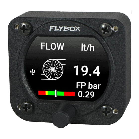
- Page 54 FLYBOX ® Operating Instructions To move between the screens of the fuel computer, turn the knob to the right and left. The following are the various screens with explanations of their meaning. If enabled, the fuel pressure is always shown at the bottom of all screens.
- Page 55 FLYBOX ® Operating Instructions REMAIN: (Remaining Quantity). It represent the fuel remaining in the tank/s. According to the selected unit measure the quantity is indicated in liters (Lt) or gallons (Gal). WARNING: The remaining fuel displayed here is not a...
- Page 56 FLYBOX ® Operating Instructions RANGE: Display the range calculated considering the fuel remaining, the actual fuel flow ground speed furnished by the GPS. If the display shows “WAITING GPS RMC” it means that the GPS is not connected, turned off or it don't have the fix.
- Page 57 FLYBOX ® Operating Instructions RESERVE: Display the fuel remaining destination; destination is intended as the approaching GPS waypoint. If the number is negative it means that there is not enough fuel to reach the destination. To enable this indication you must connect an external GPS and enable the “RMB”...
-
Page 58: Logger
When the USB flash drive is plugged-in to the device to be logged or to any other instrument of the Omnia57 series installed and clustered via the CAN bus, a white icon will appear on the display indicating that the flash drive is connected. -
Page 59: Technical Specifications
● Open-collector alarm output (max 300mA, active low). This output can also be used to send a tone in the intercom, using the Flybox optional device code 105899. ● Operating temperature range: -20 ~ +70°C. ● Humidity: 90% max (without condensation). -
Page 60: Warranty
Products is not intended to be used. Flybox®, after verification of the complaint and confirmation that the defect is covered by warranty, at its sole discretion, will either replace or repair the Products at no costs for the customer. -
Page 61: Term Of Use And Disclaimer
FLYBOX ® Disclaimer Term of Use and Disclaimer Limitation of Liability In no event shall MICROEL s.r.l. be liable for any direct, indirect, punitive, incidental, special consequential damages whatsoever arising out of or connected with the use or misuse of its products. - Page 62 WARNING: All photos, data, drawings, instruments layouts, technical solutions and data representation you find in this document or watching at FLYBOX® instruments working and/or you can access by means of any other media, including web sites, are sole property of MICROEL s.r.l., cannot be copied or imitate without a written permission of MICROEL s.r.l.
- Page 63 Flybox® is a registred brand of Microel s.r.l.- Italy www.flyboxavionics.it MICROEL s.r.l. Via Mortara 192-194 27038 Robbio (PV) - ITALY Tel +39-0384-670602 - Fax +39-0384-671830...
Need help?
Do you have a question about the Omnia57 Series and is the answer not in the manual?
Questions and answers