Table of Contents
Advertisement
Advertisement
Table of Contents

Related Manuals for Flybox Oblo


Summary of Contents for Flybox Oblo
- Page 2 Page intentionally left blank...
- Page 3 SECTIONS STANDARD OBLÒ INSTALLATION OBLÒ-A/P INSTALLATION OBLÒ-REP INSTALLATION INSTRUMENT CONFIGURATION USING THE OBLÒ AUTOPILOT SYSTEM AUTOPILOT OPERATION USE OF THE OBLÒ-REP TECHNICAL SPECIFICATIONS...
- Page 4 Flybox ® Introduction Thank you for purchasing a Flybox® product. We hope it provides many years of service to you, becoming a useful instrument for easy and immediate consultation. Developing Oblò our intent was to create a compact and lightweight attitude indicator / EFIS, easy to install and to use.
- Page 5 Flybox ® Important notices & warnings NOTE: Keep this manual in the aircraft. This document must accompany the instrument in the event of change of ownership. NOTE: This device is intended for installation onto non type certified aircraft only, because it has no aviation certifications.
- Page 6 Flybox ® Important notices & warnings CAUTION: The software of this instrument can be subject to change, update, addition or removal of functions, so also the operating mode of the instrument can be subject to change. Always refer to the installation and operating manual updated with the software version used in your instrument.
-
Page 7: Table Of Contents
Flybox ® Index INDEX SECTION 1 - Standard Oblò installation 1.1 - Mechanical installation …….…………………………….. 1.2 - Electrical and pneumatic installation ……..………….….. General wiring hints ………………..……………….….. Optional accessories available …….….…………….…... 1.3 - Altitude serial out for transponder …………….…………. 21 1.4 - Primary actions after installation ………………...………. - Page 8 Flybox ® Index Roll ……….….………….……….........… 44 Pitch …….….………….……..…........… 45 ASI (Airspeed) ….….………...………......… ALT/VSI (Vertical scale indicator) .......… 47 Autopilot …….….……..……..….........… G-meter …….………….……..….........… GPS ….….….………….……..….........… HSI ….….….………….……..…......….… 50 Compass ……………….……..….........… ADI ….….….………….……..….........… Config …..….………….……..….........… About ……….………….……..….........… 52 FW Upgrade ..………….……..….........… 52 4.3 - Magnetic calibration ….…………........
- Page 9 Flybox ® Index 6.3 - Autopilot setup menu ………………..……..... 81 6.3.1 - “Min Spd” and “Max Spd” parameters setting …..82 6.3.2 - Roll servo setup ……………...….….….…………..6.3.3 - Pitch servo setup ……………………….…………..6.3.4 - Remote button setup ……………..….….…………..91 6.4 - Flight based test and configuration .….…….......
- Page 10 Flybox ® Page intentionally left blank Oblò / Oblò-A/P(Autopilot) User’s manual Rev.3.7...
- Page 11 Flybox ® INSTALLATION SECTION Oblò / Oblò-A/P(Autopilot) User’s manual Rev.3.7...
-
Page 12: Section 1 - Standard Oblò Installation
Flybox ® Standard Oblò installation Mechanical installation SECTION 1 1.1 MECHANICAL INSTALLATION Oblò fits in a standard 3 1/8” (80 mm) cutouts. On the panel it's necessary to make the cutout for the knob on the lower right hole. The installation location must be carefully chosen since Oblò... - Page 13 Flybox ® Standard Oblò installation Mechanical installation During use the instrument become warm so it's necessary to have some air circulation inside the instruments room, to avoid that the temperature increase over the operating limits. Avoid placing in hot locations (for example near heater vents).
- Page 14 Flybox ® Standard Oblò installation Mechanical installation Front view Oblò / Oblò-A/P(Autopilot) User’s manual Rev.3.7...
- Page 15 Flybox ® Standard Oblò installation Mechanical installation Side view Oblò / Oblò-A/P(Autopilot) User’s manual Rev.3.7...
- Page 16 Flybox ® Standard Oblò installation Mechanical installation Panel cut-out - All dimensions are in millimeters. Oblò / Oblò-A/P(Autopilot) User’s manual Rev.3.7...
-
Page 17: Electrical And Pneumatic Installation
Flybox ® Standard Oblò installation Electrical installation 1.2 ELECTRICAL AND PNEUMATIC INSTALLATION On the backpanel of the Oblò there is a 15 poles D-sub plug connector, supplied with the corresponding 15-pole receptacle, one static and one pitot port. Use 1/8” NPT male fittings to connect the static... - Page 18 Flybox ® Standard Oblò installation Electrical installation CON1 connector pinout PIN# Description +12V Main supply GND Main supply CAN H signal for autopilot control unit connection (see chap.2.2) CAN L signal for autopilot control unit connection (see chap.2.2) Open-collector alarm-out (active low) max 400mA / 5W (see chap.2.2)
- Page 19 If you connect a GPS that is not powered by the aircraft bus (for example battery-powered), connect together the ground of the GPS and of the Oblò. If no external GPS is available use the Flybox® GPS cod. 810010. Oblò / Oblò-A/P(Autopilot) User’s manual...
-
Page 20: General Wiring Hints
- Ready to use wiring (ord. cod. 802000). - GPS receiver module (ord. cod. 810010). - USB flash drive, for eventual software upgrades. - Backup battery system (ord.cod. 810020). NOTE: Visit our web page http://www.flyboxavionics.it/en/oblo.html for updated prices and informations. Oblò / Oblò-A/P(Autopilot) User’s manual Rev.3.7... -
Page 21: Altitude Serial Out For Transponder
Flybox ® Standard Oblò installation Electrical installation 1.3 ALTITUDE SERIAL OUT FOR TRANSPONDER CONNECTION If you use a transponder with serial input for receiving the altitude data, it can be connected to the Oblò by following this steps: To enable the transponder output it's required to... - Page 22 Flybox ® Standard Oblò installation Electrical installation Connection of altitude serial out for transponder: The Oblò does not require any configuration, the altitude data is transmitted once per second with the followig protocol: Baud Rate Message formatting Example Alt,space,five altitude digits,...
-
Page 23: Primary Actions After Installation
Flybox ® Standard Oblò installation Pre-flight check 1.4 PRIMARY ACTIONS AFTER INSTALLATION WARNING: Do not fly until you have performed at least the actions indicated below: 1) Airspeed bar thresholds setting: It's essential to set the airspeed thresholds (bar colors) according to the V-speeds of the aircraft on which you installed the instrument, as explained in chapter 4.2, section “ASI”. - Page 24 Flybox ® Standard Oblò installation Pre-flight check 3) Instruments panel pitch adjust: For the proper operation of the attitude indicator it's necessary to compensate the inclination of the instruments panel regards the longitudinal axis of the aircraft, as explained in chap.4.2, “Pitch” parameter.
-
Page 25: Section 2 - Oblò-A/P Installation
Flybox ® Oblò-A/P installation Mechanical installation SECTION 2 2.1 MECHANICAL INSTALLATION OBLÒ-A/P INSTALLATION Mechanical installation of Oblò A/P is identical to the standard Oblò (see chap.1.1) with the addition of: Mechanical installation of ACU autopilot control unit. Mechanical installation of servo/s. - Page 26 Flybox ® Oblò-A/P installation Mechanical installation Horizontal installation (dimensions in millimeters) Oblò / Oblò-A/P(Autopilot) User’s manual Rev.3.7...
- Page 27 Flybox ® Oblò-A/P installation Mechanical installation Vertical installation (dimensions in millimeters) Oblò / Oblò-A/P(Autopilot) User’s manual Rev.3.7...
-
Page 28: Servo/S Installation
® Oblò-A/P installation Mechanical installation SERVO/S INSTALLATION : The Flybox FX75 digital servos incorporates important safety features: It has a reliable disengaging system: situations like severe turbolence or something other kind of anomaly will not be a problem, because the pilot can take in any case the immediate control of the plane. - Page 29 Flybox ® Oblò-A/P installation Mechanical installation A software function disengage the autopilot if the pilot override the servo for more than 1 seconds. It's recommended to install also the remote disengage button, to have an immediate way to disengage the autopilot even in presence of strong turbulence.
-
Page 30: Electrical Installation
Flybox ® Oblò-A/P installation Electrical installation 2.2 ELECTRICAL INSTALLATION AUTOPILOT SYSTEM INSTALLATION: • To install the autopilot system, in addition to perform the standard installation as described in chap.1.2, you must also perform the following wirings: Oblò ==> ACU control unit ACU control unit ==>... - Page 31 Flybox ® Oblò-A/P installation Electrical installation The electrical installation consists of the following wirings: 12 Volt power supply: the power supply input is in the ACU control unit and power also the connected servos. Use wire with adequate sizing to minimize voltage drop and avoid that the wire become warm (recommended size: AWG18).
- Page 32 Flybox ® Oblò-A/P installation Electrical installation Wirings of the servos: each servo need to be connected to the ACU control unit with two wires for the power supply (use AWG18 wires) and need to be connected to the CAN bus communication line using a two-pole...
- Page 33 Flybox ® Oblò-A/P installation Electrical installation CONNECTIONS DETAIL FOR ACU CON4P CONNECTOR Socket view (from wire’s insertion side) Pin# Descriprion CAN bus communication line: CAN-H signal +12V main supply CAN bus communication line: CAN-L signal GND main supply CONNECTIONS DETAIL FOR ACU CON8P CONNECTOR Socket view (from wire’s...
- Page 34 Flybox ® Oblò-A/P installation Electrical installation CONNECTIONS DETAIL FOR FX75 SERVO CONNECTOR Socket view (from wire’s insertion side) Pin# Descriprion +12V power supply Not used Not used CAN bus communication line: CAN-L signal CAN bus termination GND power supply Not used...
- Page 35 Flybox ® Oblò-A/P installation Electrical installation Electrical connections for autopilot system *NOTE: If you use the ready-to-use wiring (ord. cod. 802010), the 120 ohm resistor between pin#3 and pin#4 is already fitted inside the connector housing of the wiring. Oblò / Oblò-A/P(Autopilot) User’s manual...
- Page 36 Flybox ® Oblò-A/P installation Electrical installation NOTE: The CAN bus termination (pin#5 connected with pin#10) must be done only on the last servo of the CAN bus line. If you install only one servo, the CAN line must be terminated on that servo.
-
Page 37: Section 3 - Oblò-Rep (Repeater) Installation
Flybox ® Oblò-REP installation Mechanical installation SECTION 3 3.1 OBLÒ-REP (REPEATER) INSTALLATION Dimensions & mechanical installation of Oblò-REP are the same of standard Oblò (see chap.1.1) Electrical installation is different and depends if the Oblò-REP is connected to a standard Oblò or if it is connected to a Oblò-A/P with autopilot control unit and... -
Page 38: Electrical Installation Oblò Standard->Oblò-Rep
Flybox ® Oblò-REP installation Electrical installation 3.1.1 ELECTRICAL INSTALLATION OBLÒ-REP CONNECTED TO A STANDARD OBLÒ Oblò / Oblò-A/P(Autopilot) User’s manual Rev.3.7... -
Page 39: Electrical Installation Oblò-A/P->Oblò-Rep
Flybox ® 3.1.2 ELECTRICAL INSTALLATION OBLÒ-REP CONNECTED TO A OBLÒ-A/P WITH AUTOPILOT NOTE: The Oblò-REP share the same CAN bus line of the autopilot system. It can be connected at any point of the CAN bus line but the length of the wiring that connects the Oblò-REP must be maximum 1 meter. - Page 40 Flybox ® SECTION Oblò / Oblò-A/P(Autopilot) User’s manual Rev.3.7...
-
Page 41: Section 4 - Instrument Configuration
Flybox ® Instrument configuration Main menu configuration SECTION 4 4.1 MAIN MENU CONFIGURATION Before using your Oblò you need to configure it; read completely this chapter and follow step by step the sections to fully configure it according to your preferences. -
Page 42: Zero Pitch
Flybox ® Instrument configuration Main menu configuration • EXIT: exit the menu and returns to the main screen. • ZERO PITCH: use this function only in flight because it reset the pitch to the actual attitude. Use only when the aircraft... -
Page 43: Setup Menu Configuration
Flybox ® Instrument configuration Setup menu configuration 4.2 SETUP MENU CONFIGURATION: • EXIT: exit the menu and returns to the main screen. • T.R.I.: (Turn rate indicator) Click the knob to enter the turn rate indicator configuration. The available settings are: : set the full scale, in degrees/seconds. -
Page 44: Ball (Slip Indicator)
Flybox ® Instrument configuration Setup menu configuration • BALL: (Slip indicator) Click the knob to enter the slip indicator configuration. The available settings are: set the full scale, in milliG. Default - Scale value=300mG. filter setting. A low value means that the... -
Page 45: Pitch
Flybox ® Instrument configuration Setup menu configuration - Adjust adjustment of the roll to compensate misalignments due to installation. On the ground, with wings of the plane perfectly leveled, rotate slowly the knob until the number at the bottom become zero, then press it to store this value. -
Page 46: Asi (Airspeed)
Flybox ® Instrument configuration Setup menu configuration • ASI: Click the knob to enter the airspeed indictor configuration. The available settings are: - Vne-Vno-Vfe-Vs-Vs0 Set the speed setpoint for the moving tape airspeed indicator. Default value=0 Km/h. NOTE: Before setting these thresholds you must choose the unit of measure (see next parameter). -
Page 47: Alt/Vsi (Vertical Scale Indicator)
Flybox ® Instrument configuration Setup menu configuration : Set the unit of measure for the airspeed indicator - Unit in kilometers per hour (Km/h), miles per hour (Mph) or knots (Kts). Default value=Km/h. : filter setting. A low value means that the readings... -
Page 48: Autopilot
Flybox ® Instrument configuration Setup menu configuration : vertical speed indicator filter setting. A low - Vsi Filter value means that the readings will be more fast and unfiltered (but subject to fluctuations), an high value means that the readings will be more slow and stable. -
Page 49: Gps
Flybox ® Instrument configuration Setup menu configuration • GPS: Click the knob to enter the external GPS configuration (if connected). The available settings are: Set the baud rate of the external GPS. - Baud: Default value=4800 bps. To check if the GPS is properly connected and the... -
Page 50: Hsi
Flybox ® Instrument configuration Setup menu configuration • HSI: Click the knob to enter the HSI (Horizontal Situation Indicator) configuration menu. The available settings are: Set the window amplitude of the cross track - XTE win.: error indicators (the XTE window is measured from the two external dots). -
Page 51: Adi
Flybox ® Instrument configuration Setup menu configuration • ADI: Click the knob to enter the attitude director indicator setup. The available settings are: 1 / 2 / 3. There are three different display mode - Mode: of the indicator: MODE 1... -
Page 52: About
Flybox ® Instrument configuration Setup menu configuration • ABOUT: On this screen it’s possible to read current software versions, useful to check if your Oblò is updated to the latest version. The version number to check is in the first row, indicated after the word “CORE”. -
Page 53: Magnetic Calibration
Flybox ® Instrument configuration 4.3 MAGNETIC CALIBRATION Oblò integrates the magnetic sensors for the heading indication. The sensors are affected by all magnetic fields present around them, which, if ignored, can lead to considerable errors in the heading indication. Magnetic fields are generated for example by ferro magnetic materials (iron, ferrites), large electric current in cables, electric motors;... - Page 54 Flybox ® Instrument configuration Magnetic calibration The calibration must be performed after the installation is complete, by following this steps: Turn on the engine and go in a place far from possible magnetic fields (metallic shed, concrete floors with metal armatures, etc..) and where is possible to execute more turn with the aircraft (on the ground).
- Page 55 Flybox ® Instrument configuration Magnetic calibration In the center of the display appear a number that indicate the rotation degrees, that starting from zero increase during the rotation of the aircraft. Continue the slow circular movement: the calibration end automatically when the number...
-
Page 56: Section 5 - Using The Oblò 5.1 - Using The Oblò
Flybox ® Using the Oblò SECTION 5 5.1 USING THE OBLO’ The Oblò is organized in 3 different pages: • Attitude indicator page • HSI (Horizontal Situation Indicator) page • Drum altimeter page By default, after power-on the Oblò shows the attitude indicator page, but you can set your preferred start page by going in the Setup menu →... -
Page 57: Attitude Indicator Page
Flybox ® 5.1.1 ATTITUDE INDICATOR PAGE: SLIP INDICATOR TURN ATTITUDE RATE INDICATOR ALTIMETER AIRSPEED PRESSURE REFERENCE VERTICAL SPEED G-METER INDICATOR COMPASS • COMPASS: Placed in the lower part of the screen, the heading/tracking indication is represented with the numerical indication at the center of the graphics. The four cardinal points are shown as N , S , W , E. - Page 58 Flybox ® Using the Oblò Attitude indicator page • The HEADING is valid either stationary or moving and during aircraft turns the indicator is fluid and continuous. It compensate for aircraft attitude so that the indication is valid also with pitch or roll inclination. If external GPS is connected you will automatically obtain the magnetic declination correction.
- Page 59 Flybox ® Using the Oblò Attitude indicator page • TURN RATE: Graphical indications of the turn rate. To set the full scale go in the Setup menu-->T.R.I.-->Scale (see chap.4.2). • AIR SPEED: The Air speed is represented with both tape and numeric indicator. The unit of measure can be km/h, Mp/h or knots.
- Page 60 Flybox ® Using the Oblò Attitude indicator page Roll scale zero -10° -20° -30° -45° -60° Horizon zero The colors used for the attitude indicator are brown for the ground and sky blue for the sky. The zero is represented by the yellow line.
- Page 61 Flybox ® Using the Oblò Attitude indicator page IMPORTANT NOTES ON USING ATTITUDE INDICATOR: • The attitude indicator may loose accuracy during the flight for the following causes: During uncoordinated, accentuated or acrobatics maneuvers. Rapid temperature changes or temperature outside the operating limit (-20°C~+70°C).
- Page 62 Flybox ® Using the Oblò Attitude indicator page • SLIP INDICATOR: It's a graphic indication of the lateral accelerations. • ALTIMETER: It include both a tape indicator and a numeric indicator. The unit of measure can be feets or meters, the range of measure is -1000~25000 feets (-300~ +7600 m).
- Page 63 Flybox ® Using the Oblò Attitude indicator page CAUTION: If the instrument's internal temperature exceeds the maximum allowed (70°C) it appears to display the message “SENSOR TEMPERATURE OUT OF HIGH LIMIT”. High temperatures can be reached for example if the aircraft is parked in the sun without any instruments panel protection.
-
Page 64: Hsi Page
Flybox ® 5.1.2 HSI PAGE: ACTUAL HEADING OR TRACKING COMPASS BUG COURSE DEVIATION COURSE INDICATOR POINTER DESTINATION DISTANCE TO GO WAYPOINT ID TIME TO GO GROUND SPEED CROSS TRACK ERROR COURSE The HSI (Horizontal Situation Indicator) page reduces pilot workload by providing heading/tracking, course reference, course deviation and other navigation aid. - Page 65 Flybox ® Using the Oblò HSI page During the flight is possible to manually switch between the heading or the tracking: keep pressed the knob for 1 second and in the menu that appear choose “HDG” or “TRK”. ● COMPASS BUG: The compass bug can be freely moved by the pilot by clicking the knob and rotating to select a new heading/tracking.
-
Page 66: Drum Altimeter Page
Flybox ® ● CROSS TRACK ERROR: It shows the numerical indication of the deviation from the selected course (in kilometers (KM), Nautical miles (NM) or Miles (MI), depending on what you have set on the HSI setup menu). 5.1.3 DRUM ALTIMETER PAGE:... -
Page 67: Section 6 - Autopilot System
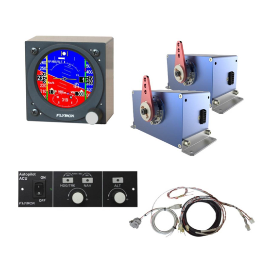
NOTE: Upgrade your Oblò to the latest version before using the autopilot function (check web site http://www.flyboxavionics.it/en/software-updates.html) - Autopilot Control Unit (Flybox® ACU). - 1 Flybox® FX75 digital servo for roll control. - 1 Flybox® FX75 digital servo for pitch control. Oblò / Oblò-A/P(Autopilot) User’s manual... -
Page 68: Autopilot Overview
Flybox ® Autopilot system Autopilot overview AUTOPILOT OVERVIEW: The autopilot system can use 1 or 2 servos, that need to be connected to the control stick for roll and pitch control. The available functions are: • Horizontal navigation (roll axis control): - Magnetic heading hold. - Page 69 Flybox ® Autopilot system Autopilot overview ON/OFF switch ON led indicator “HDG/TRK” button with led (led on when autopilot is HDG/TRK knob for engaged in HDG/TRK mode) heading/tracking setting “NAV” button with led (led on when autopilot is engaged in NAV mode) “ALT”...
-
Page 70: Remote Disengage Button
Flybox ® Autopilot system Autopilot overview REMOTE DISENGAGE BUTTON: It's recommended to install also the remote disengage button, that operate in this way: - With autopilot engaged: push shortly to disengage. - With autopilot disengaged: push for 2 seconds to engage it. -
Page 71: Autopilot System Configuration
Flybox ® Autopilot configuration 6.2 AUTOPILOT SYSTEM CONFIGURATION After the physical installation of the autopilot system it's required to check the connections and configure the parameters, as explained in the following two chapters. The operations that you will perform in sequence are the following: •... -
Page 72: Servo/S Calibration
Flybox ® Autopilot configuration 6.2.1 SERVO/S CALIBRATION The servo/s calibrations is GROUND BASED. The calibration procedure is mandatory: if you try to engage the autopilot without first calibrate the servo, the Oblò will show the error message “AUTOPILOT DISENGAGE! ROLL/PITCH SERVO CALIB”. - Page 73 Flybox ® Autopilot configuration Servo/s calibration • To begin the calibration procedure: - Press for 1 second the knob to enter in the function menu. - Rotate the knob to select the “Setup” menu and click to enter. - Rotate the knob to select the “Autopilot” menu and click to enter.
- Page 74 Flybox ® Autopilot configuration Servo/s calibration - Press the knob to start the calibration and follow the onscreen instructions; for example if you have installed the servos on both roll and pitch axis the complete procedure will be as follows: ●...
- Page 75 Flybox ® Autopilot configuration Servo/s calibration ● Step#6: position the control stick to the left limit (without forcing). Click the knob or the remote button to store the position and go to the next step. ● Step#7: position the control stick to the right limit (without forcing).
- Page 76 Flybox ® Autopilot configuration Servo/s calibration NOTE: If appears the message “BAD MECHANICAL INSTALLATION! NOT ENOUGH SERVO TRAVEL” it means that the servo is not correctly installed, as the travel of the servo arm is too small to function properly. In this case you should modify the mechanical installation, for example by using an outer hole of the servo arm.
- Page 77 Flybox ® Autopilot configuration Servo/s calibration SERVO/S CALIBRATION CHECK WARNING: Once finished the calibration you must execute this check (ground based): - With the Oblò and ACU control unit turned on, insert the autopilot on roll axis by pressing the “ H D G / T R K ”...
-
Page 78: Communications Check
Flybox ® Autopilot configuration 6.2.2 COMMUNICATIONS CHECK This check must be performed GROUND BASED. - Turn on Oblò instrument only. - Turn on ACU control unit and check that appear “AP:OFF” in the top left corner of the display. If no message appear means that there is a communication problem between Oblò... -
Page 79: Remote Button Operation Check
Flybox ® Autopilot configuration 6.2.3 REMOTE BUTTON OPERATION CHECK This check must be performed GROUND BASED. - Engage the autopilot by pressing the “HDG/TRK” button on the ACU (check the message “AP:HDG” on the Oblò display). - Press the remote disengage button and check that the message “AP:HDG”... -
Page 80: Servo Torque Check
Flybox ® Autopilot configuration 6.2.4 SERVO TORQUE CHECK This check must be performed GROUND BASED. - Engage the autopilot by pressing the “HDG/TRK” button on the ACU (check the message “AP:HDG” on the Oblò display). - Force the control stick to the left or right limit, so that... -
Page 81: Autopilot Setup Menu
Flybox ® Autopilot configuration 6.3 AUTOPILOT SETUP MENU The parameters configuration is performed on the Oblò instrument. During the configuration it's required to turn on also the ACU control unit but without engaging the autopilot (so on the ACU control unit turn on the ON/OFF switch and don't press any other button). -
Page 82: Minspd" And "Maxspd" Parameters Setting
Flybox ® Autopilot configuration Autopilot setup menù 6.3.1 “MINSPD” AND “MAXSPD” PARAMETERS SETTING This settings must be performed GROUND BASED. The autopilot system measures the airspeed and allows the pilot to set the minimum and maximum operating speed to ensure that the aircraft is in safe conditions when the autopilot is engaged. - Page 83 Flybox ® Autopilot configuration Autopilot setup menù MAX SPD: Select the maximum airspeed at which the autopilot will fly the aircraft. The unit of measure is the same set for the ASI (see Setup menu → ASI → Unit). With autopilot engaged, if the airspeed rises above the maximum, it enters to an airspeed hold mode, to restore and maintain approximately the maximum airspeed.
-
Page 84: Roll Servo Setup
Flybox ® Autopilot configuration Autopilot setup menù 6.3.2 ROLL SERVO SETUP This settings must be performed GROUND BASED. This settings can be performed inside the “ROLL SERVO” menu, that can be reached in this way: - Press for 1 second the knob to enter in the function menu. - Page 85 Flybox ® Autopilot configuration Autopilot setup menù • “GAIN” PARAMETER CHECK This check must be performed GROUND BASED. GAIN: This parameter specify how fast or slow the autopilot responds to deviations between commanded and actual heading/tracking. For now check only that the parameter is at the default value (10), because it will be set in flight as explained later in chap.6.4.1.
- Page 86 Flybox ® Autopilot configuration Autopilot setup menù • “TURN RATE” PARAMETER SETTING This settings must be performed GROUND BASED. TURN RATE: Select your desired target rate of turn when autopilot is engaged. The unit of measure is degrees per second and the range min-max is from 0.5°/s to 3.0°/s.
-
Page 87: Pitch Servo Setup
Flybox ® Autopilot configuration Autopilot setup menù 6.3.3 PITCH SERVO SETUP This settings must be performed GROUND BASED. This settings can be performed inside the “PITCH SERVO” menu, that can be reached in this way: - Press for 1 second the knob to enter in the function menu. - Page 88 Flybox ® Autopilot configuration Autopilot setup menù • “GAIN” PARAMETER CHECK This check must be performed GROUND BASED. GAIN: This parameter specify how fast or slow the autopilot responds to deviations between commanded and actual altitude. For the moment check only that the parameter is at the default value (13), because it will be set in flight as explained later.
- Page 89 Flybox ® Autopilot configuration Autopilot setup menù • “CLIMB” PARAMETER SETTING This setting must be performed GROUND BASED. CLIMB: This parameter sets the average vertical speed for autopilot-commanded climbs.The unit of measure is meters/second or feet/minute, depending on what you have choosen for the altimeter.
- Page 90 Flybox ® Autopilot configuration Autopilot setup menù • “MAX PITCH” PARAMETER SETTING This setting must be performed GROUND BASED. MAX PITCH: This parameter specifies a maximum pitch angle which the autopilot will not exceed during climbs or descents. Set an appropriate bank limit, the min-max range is: 5~20 degrees (Default value = 10).
-
Page 91: Remote Button Setup
Flybox ® Autopilot configuration Autopilot setup menù 6.3.4 REMOTE BUTTON SETUP The 'Remote Button' setup menu can be reached in this way: - Press for 1 second the knob to enter in the function menu. - Rotate the knob to select the “Setup” menu and click to enter. - Page 92 Flybox ® Autopilot configuration Autopilot setup menù • HtoE enable (Hold to engage enable): Enable (YES) or disable (NO) the function to engage the autopilot when the button is pressed for 2 seconds. The default value is “NO” so the remote button will only serve to disengage the autopilot when already engaged.
-
Page 93: Flight Based Test And Configuration
Flybox ® Autopilot configuration 6.4 FLIGHT BASED TEST AND CONFIGURATION During this phase you calibrate the servo response to match your aircraft flight dynamics. Although flight testing may be carried out in different ways, it's recommended to follow the procedures indicated in the following chapters. - Page 94 Flybox ® Autopilot configuration Flight based test and configuration Before starting the first test flight verify once more for safety that all the parameters are correctly set: - Press for 1 second the knob to enter in the function menu.
-
Page 95: Autopilot Setup - Roll Axis (Flight Based)
Flybox ® Autopilot configuration Flight based test and configuration • AUTOPILOT ENGAGE AND “GAIN” PARAMETER - Start the flight and when you are in safe condition (read chap.6.4) insert the autopilot by pressing the “HDG/TRK” button on the ACU control unit (the led will turn on as confirmation). - Page 96 Flybox ® Autopilot configuration Flight based test and configuration The “Gain” parameter selects the amount of autopilot activity for a given roll angle error (that is the difference between the desired heading/tracking and the actual heading/tracking). With low “Gain” values (minimum=1) the autopilot system is very slow with few corrections, with high “Gain”...
- Page 97 Flybox ® Autopilot configuration Flight based test and configuration • HEADING/TRACKING CHANGE During this phase you observe the autopilot behavior during a turn, further optimizing the “Gain” parameter which as said is what establishes the autopilot response. - With the autopilot engaged in “HDG/TRK” mode, start an autopilot commanded turn by rotating the HDG/TRK knob on the ACU control unit.
- Page 98 Flybox ® Autopilot configuration Flight based test and configuration • CHECK OF THE PARAMETERS “TURN RATE” AND “MAX ROLL BANK” It's possible to check if the values set for the turn rate and for the maximum bank angle are compatible by measuring the time the autopilot takes to complete a turn: for example if in the “Turn Rate”...
-
Page 99: Autopilot Setup - Pitch Axis (Flight Based)
Flybox ® Autopilot configuration Flight based test and configuration 6.4.2 AUTOPILOT SETUP – PITCH AXIS (FLIGHT BASED) - Start the flight and when you are in safe condition (read chap.6.4), at the desired altitude and trimmed for level flight, insert the autopilot by pressing the “ALT” button on the ACU control unit (the led will turn on as confirmation). - Page 100 Flybox ® Autopilot configuration Flight based test and configuration • To change the “Gain” parameter: - Press for 1 second the knob to enter in the function menu. - Rotate the knob to select the “Setup” menu and click to enter.
- Page 101 Flybox ® Autopilot configuration Flight based test and configuration • Altitude change: During this phase you observe the autopilot behavior during an altitude change, further optimizing the “Gain” parameter which as said is what establishes the autopilot response. - With the autopilot engaged in “ALT” mode, start an autopilot commanded altitude change by rotating the ALT knob on the ACU control unit.
-
Page 102: Section 7 - Autopilot Operation
Flybox ® Autopilot operation SECTION 7 7.1 AUTOPILOT OPERATION The autopilot indications appear when you turn on the ACU control unit, and are the following: • AUTOPILOT STATUS INDICATOR: • AP:OFF when autopilot is not engaged. • AP:HDG when autopilot is engaged and follow/holds the magnetic heading. - Page 103 Flybox ® Autopilot operation Available indications • ALTITUDE BUG: The altitude bug is a graphical representation on the altimeter indicator, at the altitude that the autopilot must maintain/reach. The bug can be set by turning the “ALT” knob on the ACU control unit. While setting the altitude with the “ALT”...
- Page 104 Flybox ® Autopilot operation Available indications • HEADING/TRACKING BUG: The heading/tracking bug is a graphical representation heading/tracking indicator, heading/tracking that the autopilot must maintain/reach. The bug can be set by turning the “HDG/TRK” knob on the ACU control unit. While setting the heading/tracking with the “HDG/TRK”...
-
Page 105: How To Engage And Disengage The Autopilot
Flybox ® Autopilot operation 7.2 HOW TO ENGAGE AND DISENGAGE THE AUTOPILOT • The autopilot system can be engaged in several ways: ● Pressing the “HDG/TRK” button on the ACU control unit (the led will turn on). ● Pressing the “NAV” button on the ACU control unit (the led will turn on). - Page 106 Flybox ® Autopilot operation Engage/disengage ● The attitude indicator of the Oblò reports invalid data. ● The actual bank or pitch angle is out of the maximum ● Only for “NAV” mode, if no valid data are received or no flight plane/GOTO has been done on the external GPS.
- Page 107 Flybox ® Autopilot operation Engage/disengage NOTE: A display alert comes when the autopilot cannot engage for any of the above conditions. Press the knob of the Oblò to cancel this alert. The autopilot system can be disengaged by the pilot via the following actions: ●...
-
Page 108: Details Of Operation
Flybox ® Autopilot operation 7.3 DETAILS OF OPERATION PREFLIGHT CHECK: Everytime you intend to use the autopilot system perform the following checks on ground: Move to its limits the flight controls (with autopilot disengaged) and check that full manual control is allowed. - Page 109 Flybox ® Autopilot operation Details of operation • ENGAGE AUTOPILOT “HDG/TRK” MODE (HEADING OR TRACKING HOLD/CHANGE): - Once in flight and with Oblò already turned on, turn on the ACU control unit via the ON/OFF switch. - Choose between heading or tracking (press the knob on the Oblò, turn it to select HDG or TRK and press...
- Page 110 Flybox ® Autopilot operation Details of operation • AUTOMATIC COURSE REVERSAL: The automatic course reversal mode may be used as an emergency aid to pilot who inadvertently enters IMC conditions and need to execute an immediate course reversal. - With autopilot engaged in “HDG/TRK” or “NAV” mode, press for 3 seconds the “HDG/TRK”...
- Page 111 Flybox ® Autopilot operation Details of operation • ENGAGE AUTOPILOT IN “NAV” MODE (FLIGHT PLANE OR GOTO NAVIGATION): - Once in flight and with the Oblò already turned on, turn on the ACU control unit via the ON/OFF switch. - Set a flight plane or a GOTO in the external GPS.
- Page 112 Flybox ® Autopilot operation Details of operation • ENGAGE AUTOPILOT IN “ALT” MODE (ALTITUDE HOLD/CHANGE): - Once in flight and with the Oblò already turned on, turn on the ACU control unit via the ON/OFF switch. - Trim the aircraft for level flight.
- Page 113 Flybox ® Autopilot operation Details of operation • AUTOPILOT DISENGAGE: - If engaged in “HDG/TRK” mode, press the “HDG/TRK” button on the ACU control unit (led will turn off) or press the remote button (if installed). - If engaged in “NAV” mode, press the “NAV” button on the ACU control unit (led will turn off) or press the remote button (if installed).
-
Page 114: Autopilot Related Alarms
Flybox ® Autopilot operation 7.4 AUTOPILOT RELATED ALARMS The autopilot disengage automatically if it detects any anomaly; at the same time it will show an error message on display and, if enabled, activate the audio and alarm outputs. To reset an alarm click the knob. - Page 115 Flybox ® Autopilot operation Autopilot alarms • “AUTOPILOT DISENGAGED! (ROLL) or (PITCH) SERVO LIMIT”: Appears when a servo detects that the control stick is outside the operating limits. Can occur if the pilot force the control stick to the limits or can occur if the pilot try to engage the autopilot when the control stick is close to the limits.
- Page 116 Flybox ® Autopilot operation Autopilot alarms • “AUTOPILOT DISENGAGED! NAV DATA TIMEOUT” : Appears when the autopilot does not receive any data from the external GPS: - Check that the wiring between external GPS and Oblò is correct. - Check that the GPS baudrate is set in the same way of the external GPS.
-
Page 117: Important Notices - Safety Checks
Flybox ® Autopilot operation 7.5 IMPORTANT NOTICES – SAFETY CHECKS Never use the autopilot without first conduct satisfactory pre-flight check of the autopilot system and its components. Autopilot operations should be verified for correctness before flight. After every software update of the Oblò or a servos, check the correctness of the setup as explained in chap.7.3. -
Page 118: Autopilot Activation Procedure
Flybox ® Autopilot operation 7.6 AUTOPILOT ACTIVATION PROCEDURE If you already have a standard Oblò you can upgrade it to the autopilot version by purchasing the activation key (cod. 801020) and following this activation procedure. NOTE: Upgrade your Oblò to the latest version before activating the autopilot function (check web site http://www.flyboxavionics.it/en/software-updates.html) - Page 119 Flybox ® Autopilot operation Autopilot activation After purchase you will be given a numeric key to enter the Oblò in the following way: - Turn on the instrument. - Press for 1 second the knob to enter in the function menu.
- Page 120 Flybox ® Autopilot operation Autopilot activation - Insert the numerical key that you have received after purchase (turn the knob to increase/decrease the digit and press it to go to the next digit). The correct entry code will be confirmed by the “AUTOPILOT ENABLED”...
-
Page 121: Section 8 - Use Of The Oblò-Rep (Optional)
Flybox ® Use of the Oblò-REP SECTION 8 8.1 USE OF THE OBLÒ-REP (optional) Oblò-REP, connected to a main Oblò unit, allows to view the data on copilot side also. This model does not have any sensor inside, but it displays all the data available in the standard Oblò... - Page 122 Flybox ® Use of the Oblò-REP After instrument turn-on, if the Oblò-REP is unable to communicate with the main unit (for example if the main unit is not connected or turned off) it display the following screen: As soon as communication between the two instruments is established, the Oblò-REP will show the attitude...
-
Page 123: Technical Specifications
Flybox ® SECTION 9 9.1 TECHNICAL SPECIFICATIONS - Dimensions: 83 x 83 x 61 mm. - Weight: 300 g. - Operating temperature range: -20 ~ +70°C. - Power supply: 10~20 Vdc, 0.26 A. - Connections via DSUB 15 poles connector. -
Page 124: Appendix "A" Altimeter Calibration
Flybox ® APPENDIX “A” ALTIMETER CALIBRATION The altimeter is calibrated in factory and usually requires no calibration. Perform this procedure only if you notice large differences compared to a reference altimeter. 1. Turn-on the Oblò and press the knob for 1 second to enter in the function menu. - Page 125 Flybox ® 4. Turn-on the reference altimeter and set it to QFE, unit of measure: milliBAR. 5. Warm up both instruments for about 15 minutes. 6. In the Oblò select the “Offset” parameter and click the knob to enter. 7. Read the pressure measured by the reference altimeter and adjust the Oblò...
-
Page 126: Appendix "B" - Detail Of Optional Wirings
Flybox ® APPENDIX “B” DETAIL OF OPTIONAL WIRING FOR OBLO’ (cod. 802000) Oblò / Oblò-A/P(Autopilot) User’s manual Rev.3.7... - Page 127 Flybox ® DETAIL OF OPTIONAL WIRING FOR OBLO’-A/P (cod. 802010) Oblò / Oblò-A/P(Autopilot) User’s manual Rev.3.7...
-
Page 128: Appendix "C" - Detail Of Optional Gps Module
Follow this schematic if you have the ready to use Flybox® wirings for Oblò (cod.802000 or 802010): The Flybox® GPS has one shielded wire with two poles: RED WIRE: +5V positive supply (connect to wire “5V Flybox GPS” of Flybox® wiring). - Page 129 Case 2 Follow this schematic if you made by yourself the wirings: The Flybox® GPS has one shielded wire with two poles: RED WIRE: +5V positive supply (connect to pin #9 of Oblò connector) BLACK WIRE: GPS TX signal (connect to pin#14 of Oblò...
-
Page 130: Warranty
Flybox ® Check frequently our web site www.flyboxavionics.it to see if there are any software updates. WARRANTY: This product is warranted to be free from defects for a period of 12 months from the user invoice date. The warranty only covers manufacturer defects and... -
Page 131: Revision History
Minor corrections WARNING: All photos, data, drawings, instruments layouts, technical solutions and data representation you find in this document or watching at Flybox® instruments working and/or you can access by means of any other media, including web sites, are sole property of MICROEL s.r.l., cannot be copied or imitate without a written permission of MICROEL s.r.l. - Page 132 MICROEL s.r.l. Via Mortara 192-194 27038 Robbio (PV) - ITALY Tel +39-0384-670602 - Fax +39-0384-671830 www.flyboxavionics.it...
Need help?
Do you have a question about the Oblo and is the answer not in the manual?
Questions and answers