Table of Contents
Advertisement
Quick Links
Advertisement
Table of Contents

Related Manuals for Flybox Oblo backup system 2.0


Summary of Contents for Flybox Oblo backup system 2.0
- Page 1 ® Oblò backup system 2.0 Revision#1.0, 07/11/2018...
- Page 2 Page intentionally left blank...
- Page 3 SECTIONS MECHANICAL INSTALLATION ELECTRICAL INSTALLATION OPERATING INSTRUCTIONS TECHNICAL SPECIFICATIONS...
- Page 4 FLYBOX ® Introduction Thank you for purchasing a Flybox® product. We hope it fully satisfy you. SYMBOLS USED IN THE MANUAL NOTE: Used to highlight important informations. CAUTION: Used to warn the user and indicate a potentially hazardous situation or improper use of the product.
- Page 5 FLYBOX ® Important notices & warnings NOTE: Keep this manual in the aircraft.This document must accompany the device in the event of change of ownership. NOTE: This device is intended for installation onto non type certified aircraft only, because it has no aviation certifications.
-
Page 6: Table Of Contents
FLYBOX ® Index INDEX SECTION 1 - Mechanical installation 1.1 - Mechanical installation ……………….………………….. 1.2 - Installation notices ……..………………………………… SECTION 2 - Electrical installation 2.1 - Electrical installation ………..……..………………….…. Ferrite mounting …………..……..………………….…. 10 SECTION 3 - Operating instructions 3.1 - Description and use of the device ….….…………………. 12 3.2 - Normal operating procedure ………………………………... -
Page 7: Section 1 - Mechanical Installation
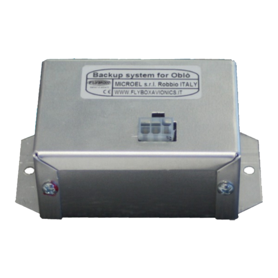
FLYBOX ® Mechanical installation SECTION 1 1.1 MECHANICAL INSTALLATION The aluminum enclosure can be fixed using the two holes on the flanges. Dimensions in millimeters Oblò backup system 2.0 User’s manual Rev. 1.0... -
Page 8: Installation Notices
FLYBOX ® Installation notices 1.2 INSTALLATION NOTICES ● This device contains a Ni-Mh battery pack, with operating temperature range 0~45°C. Outside of these limits the battery is not charged, need to install it away from heat sources (for example heater vents). If possible choose an area where there is some air circulation. -
Page 9: Section 2 - Electrical Installation
FLYBOX ® Electrical installation SECTION 2 2.1 ELECTRICAL INSTALLATION Below is the wiring connection for the 6 pin Molex minifit-jr connector of the device. Included in the kit there are the corresponding socket connector and the crimp terminals. Socket connector,... - Page 10 FLYBOX ® Electrical installation NOTE: - This device was designed to drive one or two Oblò instrument. If you connect other instruments note that the output current limit is 0.45 Amps. - The power supply can be taken either from a line that remains energized during engine start (ie master bus) or from a line that remains off during engine start.
-
Page 11: Description And Use Of The Device
FLYBOX ® Description and use of the device SECTION 3 3.1 DESCRIPTION AND USE OF THE DEVICE The Backup System for Oblò is an electronic device that contains a Ni-Mh battery pack and an electronic system that manage the battery charging. It is designed to drive one or two Oblò... - Page 12 FLYBOX ® Description and use of the device Ground based recharging: To accomplish ground based charging, turn on the aircraft master switch and keep turned on for 3-4 hours, to allow the backup system to be charged. Leave all other aircraft loads in their off state. After 3-4 hours the internal battery is fully charged, turn off the master switch.
- Page 13 FLYBOX ® Description and use of the device To avoid damage to the battery pack you must avoid to fully discharge it (the battery voltage should never drop below 9.5 Volt). If you have connected one Oblò instrument, it will turn off when voltage drop below 10V, or you will notice continuous turn-off/turn-on.
-
Page 14: Normal Operating Procedure
FLYBOX ® Normal operating procedures 3.2 NORMAL OPERATING PROCEDURES For normal operation the following is the recommended operating procedures: Start-up procedure: ● Prior to turning on the aircraft master switch, turn on any equipment that derives power from the backup system. -
Page 15: Endurance Testing
FLYBOX ® Endurance testing 3.3 ENDURANCE TESTING At least once a year perform this test to check the endurance capability of the backup system: 1. Shut down the aircraft master switch. 2. Turn on the equipment connected to the backup system. -
Page 16: Warning Led Notifications
FLYBOX ® Warning led notifications 3.4 WARNING LED NOTIFICATIONS The warning led is used to indicate any faults in the system or in the internal battery pack. When power supply is applied to the backup system, the led lights up for 3 seconds to confirm correct operation. -
Page 17: Section 4 - Technical Specifications
FLYBOX ® Technical specifications SECTION 4 4.1 TECHNICAL SPECIFICATIONS - Dimensions: 105.0 x 57.2 x H43 mm. - Electrical connections using 6-poles Molex minifit-jr connector (included). - Operating temperature range: -10 ~ +60 °C. - Charge operating temperature of the internal battery pack: 0 ~ 45 °C. -
Page 18: Warranty
First release WARNING: All photos, data, drawings, instruments layouts, technical solutions and data representation you find in this document or watching at FLYBOX® instruments working and/or you can access by means of any other media, including web sites, are sole property of MICROEL s.r.l., cannot be copied or imitate without a written permission of MICROEL s.r.l. - Page 19 Page intentionally left blank...
- Page 20 MICROEL s.r.l. Via Mortara 192-194 27038 Robbio (PV) - ITALY Tel +39-0384-670602 - Fax +39-0384-671830 www.flyboxavionics.it...
Need help?
Do you have a question about the Oblo backup system 2.0 and is the answer not in the manual?
Questions and answers