
Subscribe to Our Youtube Channel
Related Manuals for RDZ UMHPI


Summary of Contents for RDZ UMHPI
- Page 1 Chiller and Heat Pumps UMHPI Controller UMHPI on-board electronic user controller USER MANUAL...
- Page 3 Notes Serie / Series / Serie / Serie / Série UMHPI INDUSTRIAL INVERTER AIR/WATER HEAT PUMPS WITH AXIAL FANS Possible wasted electrical or electronic devices/products should not be located together with normal domestic waste, but disposed according to the current WEEE law in compliance with the European Directive 2012/19/UE and following modifications 2003/108/EC. Please inform yourself at your local Administration or at your reseller in case the product will be replaced with a similar one.
-
Page 4: Table Of Contents
UMHPI Industrial inverter air/water heat pumps with axial fans INDEX CONSERVATION OF THE MANUAL ............................4 GRAPHIC SYMBOLS USED IN THE MANUAL ..........................4 PERMITTED USES................................4 GENERAL SAFETY GUIDELINES ............................4 PERSONAL PROTECTION EQUIPMENTS ..........................4 HEALTH AND SAFETY OF WORKERS ............................5 PURPOSES AND CONTENTS OF THE MANUAL ........................ - Page 5 “GI” ........................35 ODULE 11.11 CONFIGURATION PARAMETERS OF THE HEATING DEVICES – M .................. 35 FOR THE MODEL UMHPI V R08=-20°C............................ 36 11.12 CONFIGURATION PARAMETERS OF UMHPI V ........................36 ALARMS ..................................37 12.1 FLOW SWITCH [E06] ................................37 12.2...
-
Page 6: Conservation Of The Manual
PERSONAL PROTECTION EQUIPMENTS It’s necessary to use the below personal protective equipment when operating and maintaining the UMHPI/UMHPI V units, Protective clothing: Service man or who operates on the plant systems should wear protective clothing that complies with the basic safety requirements currently in force. -
Page 7: Health And Safety Of Workers
4 PURPOSES AND CONTENTS OF THE MANUAL This manual provides basic information as for the configuration of the panel controller of UMHPI/UMHPI V units. It is addressed to the installer and the user of the unit: it allows you to operate this equipment efficiently, even if the user does not... -
Page 8: System Architecture
CB = on-board (Master) controller located on the front panel of the unit. As for UMHPI V models and if are equipped with the optional kit mod. GI, the system includes an additional controller. b) SL1 = on-board (Slave 1) controller inside the electric panel of the unit. -
Page 9: User - Cb Master Controller Interface
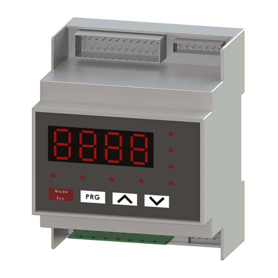
UMHPI Industrial inverter air/water heat pumps with axial fans 6 USER – CB MASTER CONTROLLER INTERFACE It is used to select the operating mode, and to reset the manual resetting alarms. The operating mode changes as per the sequence below each time you press the Mode button: off ... -
Page 10: Analog Inputs
**t17 Injection temperature (°C) (*) Present in the UMHPI V models or with the optional kit mod. Gi in the the models UMHPI. (**) Present in the UMHPI V models PARAMETERS CATEGORIES The parameters are classified into groups, each group is identified by a 3-digit code, while the index of each parameter is preceded by a letter. -
Page 11: Display
(1) Only for the model 125 (2) Not selectable if the GI2 is present Standard on UMHPI V models and is present in the optional kit mod. Gi, in addition, the following I/O resources can be configured: Factory Setting Terminals of... -
Page 12: Operation Logic
- NO2= Normally open NC2E (phase) - NC2= Normally-Closed (3) Not selectable in the models of UMHPI V. 7 OPERATION LOGIC The following operation logics are enabled by the master controller (CB), mounted on the front panel of the unit. -
Page 13: Setpoint Adjustment From 0-10V Input
UMHPI Industrial inverter air/water heat pumps with axial fans Heating SETPOINT ADJUSTMENT FROM 0-10V INPUT Another type of setting that allows to change the setpoint by adding (or subtracting) a value in function of the 0-10V analogue input (if enabled). To enable the function, you must set the H21 parameter to be 40, and change the values of the parameter b15 (range 0-10), taking into account that: if the input is at 0 volts you will have the actual set point: set point (Coo/Hea) - b15/2. -
Page 14: Operation By Mean Of The Thermoregulator (Default)
UMHPI Industrial inverter air/water heat pumps with axial fans The adjustment of the circulator is linear (see Paragraph 7.3.5). Please see paragraph 11.6 for changing the parameters. 7.3.1 OPERATION BY MEAN OF THE THERMOREGULATOR (Default) During this operating mode (P03=1, default), the thermo-regulator actuates the circulator; after a time delay of P01 seconds from startup of the circulator pump, the compressor also will turn on. -
Page 15: Multicompressors
UMHPI Industrial inverter air/water heat pumps with axial fans • P10: Delta modulating pump (°C) − In cooling mode: ΔT= [Water inlet temperature] – [Water outlet temperature] − In heating mode: ΔT = [Water outlet temperature] – [Water inlet temperature] Example in cooling: If the difference in temperature between water inlet and outlet is greater than P09 + P10, the pump will run at maximum speed. -
Page 16: Emergency Conditions
UMHPI Industrial inverter air/water heat pumps with axial fans − The requests of capacity decreasing will be done by selecting among the whole running compressors at the nominal capacity. The selection will consider the one with higher hours number of operation. -
Page 17: Transitory Of Starting
UMHPI Industrial inverter air/water heat pumps with axial fans • HzMaxReg = Maximum working frequency of the compressor in cooling mode based on the limitations described in the previous paragraphs The following curve shows the adjustment without integral component (b07 = 0) During the start-up, the compressor initiates at the minimum speed C12 or C14 (as defined from the envelope) for a given time period equal to C11 and then changes its speed to C13 for a period equal to C51-C11. -
Page 18: Fan Speed Control In Heating Mode
UMHPI Industrial inverter air/water heat pumps with axial fans 7.5.3 FAN SPEED CONTROL IN HEATING MODE The fan speed control in heating mode follows the diagram shown below, where: F10 = Delta cut-off of the fan in cooling/heating mode F11 = Cut-off hysteresis in cooling/heating mode... -
Page 19: Alarm Notification
UMHPI Industrial inverter air/water heat pumps with axial fans ALARM NOTIFICATION You can configure a digital output for alarm notification function. In order to enable such function, you should enter into the parameters as following: press PRGPSSPRG(then insert the service password) PRG PAr PRG CnF See paragraph 11.2. -
Page 20: Memory Of The Sensor In Heating Mode
- Or after a period of time equal to b06 seconds (default 45 seconds). For each UMHPI unit (except the last unit of the cascade), you must implement a relay (not included), controlled by the output 230VAC NO1 and N located on the terminal block, that can enable through its free contacts COM and NO the ADI2-ADI2 digital... -
Page 21: Heating Mode On Domestic Hot Water Tank
UMHPI Industrial inverter air/water heat pumps with axial fans NOTE: turning off the unit remotely (onoff-onoff terminals), or by the on board keyboard, or by a remote keyboard does not affect the DHW operating mode. Once the H10 parameter is set to be 1, the unit switches to DHW priority as soon as powered. The on board display shows the temperature measured by the sensor placed inside the DHW water tank. -
Page 22: Remote Functions
This function is recommended in the case of utilization of two or more UMHPI units installed in cascade configuration and linked through a hydronic connection to the same accumulation tank of domestic hot water;... -
Page 23: Plant Circuit Remote Sensor
In case of using a 3-way changeover valve with 2 contacts for power supply (with spring return), [terminals: NO1 – N] For the models UMHPI 260, this function can be activated only with the presence of the optional “GI” module. 7.15 PLANT CIRCUIT REMOTE SENSOR... -
Page 24: Main Circuit Vee, Double Control
UMHPI Industrial inverter air/water heat pumps with axial fans The cycle described above is represented on the pressure-enthalpy diagram, at the side of the diagram where represented the point 2 the conditions of the gas at the end of compression with suction always carried out under the conditions of point 1 but without vapor injection. -
Page 25: Vapor Injection Valve (Veiv)
UMHPI Industrial inverter air/water heat pumps with axial fans Before proceeding, the equation must be: in continuous mode, fulfilled or unfulfilled respectively for v11 minutes (fulfillment) and v12 minutes (unfulfillment). At the power-on, the unit turns on with unfulfilled equation. -
Page 26: Auxiliary Electric Heater Of The Plant In Defrost Cycle
UMHPI Industrial inverter air/water heat pumps with axial fans (*) Alternatively, it is possible to use another output DO or OC, see paragraph 6.5. 8.1.2 AUXILIARY ELECTRIC HEATER OF THE PLANT IN DEFROST CYCLE During the defrosting cycle (see Paragraph 7.6), by setting r21=1 (in addition to r10=1 and r24=1 or 3) the electric heater of the plant side will be activated if required (regulating temperature lower than the water setpoint - r11 (°C)), without waiting for the... -
Page 27: Activation Of Auxiliary Electric Heater And Boiler During The Joint/In Substitution Operation To The Compressor
[Boiler and/or electric heater] IN SUBSTITUTION OPERATION For the models UMHPI V the parameter r08 =-20°C When changing the values of the parameters r22, r28, r08, you have to respect the following condition: r22 ≥ r28 ≥ r08. You can remove the zone corresponding to the “in joint operation I” just by putting r22=r28; you can also remove the zone corresponding to the “in joint operation II”... -
Page 28: In Joint Operation (Area Ii)
UMHPI Industrial inverter air/water heat pumps with axial fans 8.3.3 IN JOINT OPERATION (AREA II) If the outdoor air temperature is included between r28 and r08, the compressor will operate in synergy with the auxiliary electric heaters. In this operation area, the devices will start operation in the following working order: at first the boiler will start the operation, then the heat pump and the plant circuit auxiliary electric heaters will start operation after a period of time given by r12 (in minutes) and after r16 (in minutes) the DHW auxiliary electric heaters will start operation. - Page 29 UMHPI Industrial inverter air/water heat pumps with axial fans TABLE 2. JOINT OPERATION “AREA 1” ORDER OF INTERVENTION OF N° MODE OPERATION HEATING EQUIPMENTS (when the setpoint is not achieved) 1) Heat pump HEAT / Set up of 2) After r12 minutes, plant auxiliary...
- Page 30 UMHPI Industrial inverter air/water heat pumps with axial fans 3) After r15 minutes later, DHW auxiliary electric heater 1) DHW auxiliary electric heater HEAT / In HEAT OR in Set up of Set up of minutes minutes HEAT+SAN 2) After r15 minutes, heat pump...
-
Page 31: Auxiliary Systems Offset Management
UMHPI Industrial inverter air/water heat pumps with axial fans The below Table (6) shows the behavior of DHW and plant auxiliary electric heaters in all cases when the unit is operating. TABLE 6. OPERATION OF AUXILIARY ELECTRIC HEATERS AUXILIARY ELECTRIC HEATER OF PLANT AUXILIARY ELECTRIC HEATER OF DHW N°... -
Page 32: Adjuastable Set-Point
UMHPI Industrial inverter air/water heat pumps with axial fans To activate this function you should set the parameters getting access with the service password: Parameter Unit Default Value Description Terminals Notes ADI1E *H51 Digital input for the second setpoint ADI1E... -
Page 33: Available Functions With Evo Touch Controller (Optional)
INSTALLER *Vapor injection INSTALLER Inverter compressors INSTALLER **Solar INSTALLER **DHW preparer USER/INSTALLER (*) Parameters present in the UMHPI V series (**) Parameters present with the optional KIE module. 11.1 SETPOINT CONFIGURATION PARAMETERS Parameter Description Unit Default Range Visibility Admitted configuration... -
Page 34: Alarms Configuration Parameters
UMHPI Industrial inverter air/water heat pumps with axial fans Enabling of DHW production 0÷6 INSTALLER ADI2-ADI2 terminals 0 = input not assigned ST8 input configuration 0÷49 INSTALLER Serviceable input in 6 = DHW temperature exclusion of D.I.7 Configuration of digital input 2 0 = digital input not assigned 0÷30... -
Page 35: Adjustment Parameters
UMHPI Industrial inverter air/water heat pumps with axial fans 11.4 ADJUSTMENT PARAMETERS Parameter Description Unit Default Range Visibility Allowed configurations Notes Band in cooling mode °C 0÷10,0 INSTALLER Band in heating mode °C 0÷10,0 INSTALLER Differential in DHW mode °C 0÷10,0... -
Page 36: Pump Configuration Parameters
UMHPI Industrial inverter air/water heat pumps with axial fans 11.6 PUMP CONFIGURATION PARAMETERS Parameter Description Unit Default Range Visibility Allowed configurations Notes Pump ON Compressor ON delay 0÷255 INSTALLER Pump OFF compressor OFF delay 0÷255 INSTALLER 0 = continuous operation Pump operation mode 0÷1... -
Page 37: Configuration Parameters - Module "Gi
11.10 CONFIGURATION PARAMETERS – Module “GI” As for UMHPI V units and in case of installation of the optional kit module (GI2) on UMHPI units, it is possible to manage the following additional functions. Such parameters can be activated and/or adjusted by the installer from of CB master controller menu mounted on the front panel of the unit. -
Page 38: For The Model Umhpi V R08=-20°C
0÷100 INSTALLER and DHW electric heaters (G03) Boiler endowment 0÷3 INSTALLER Pump management with 0÷4 INSTALLER electric heaters ON For the model UMHPI V r08=-20°C. 11.12 CONFIGURATION PARAMETERS OF UMHPI V Parameter Description Unit Default Range Visibility Allowed configuration Note Set DSH in cooling °C... -
Page 39: Alarms
If the alarm occurs more than 3 times per hour, the alarm becomes a manual reset. 12.11 [E101] MODBUS 1 CONNECTION ERROR Standard on UMHPI V models and if present the optional kit mod. Gi, ModBus communication connection between CB and SL1 controller is wrong. Check the wiring. -
Page 40: Power Failure
Inverter 2 PFC *E951 Inverter 1 temp. sensor error *E952 Inverter 2 temp. sensor error *E961 Inverter 1 failure *E962 Inverter 2 failure *E971 Inverter 1 EEPROM error *E971 Inverter 2 EEPROM error (*) Only for the models “UMHPI 60”... - Page 44 FAE0FA000BZ.00 06/2018...
Need help?
Do you have a question about the UMHPI and is the answer not in the manual?
Questions and answers