Advertisement
Quick Links
Power Tools Service Manual
PRODUCT NAME
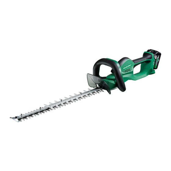
36 V Cordless Hedge Trimmer
CH 3656DA
Model
CONTENTS
REPAIR GUIDE ------------------------------------------------------------------------------------------------------------------ 1
1. Precautions on disassembly and reassembly ------------------------------------------------------------- 1
• Disassembly --------------------------------------------------------------------------------------------------- 1
• Reassembly ---------------------------------------------------------------------------------------------------- 2
• Lubrication points and type of lubricant ----------------------------------------------------------------- 8
• Tightening torque --------------------------------------------------------------------------------------------- 8
2. Precautions on disassembly and reassembly of the charger ------------------------------------------ 8
STANDARD REPAIR TIME (UNIT) SCHEDULES ---------------------------------------------------------------------- 9
Overseas Sales Management Dept.
-1-
CONFIDENTIAL
Jul. 2018
Page
C
Advertisement

Subscribe to Our Youtube Channel
Related Manuals for HIKOKI CH 3656DA


Summary of Contents for HIKOKI CH 3656DA
-
Page 1: Table Of Contents
Power Tools Service Manual CONFIDENTIAL Jul. 2018 PRODUCT NAME 36 V Cordless Hedge Trimmer CH 3656DA Model CONTENTS Page REPAIR GUIDE ------------------------------------------------------------------------------------------------------------------ 1 1. Precautions on disassembly and reassembly ------------------------------------------------------------- 1 • Disassembly --------------------------------------------------------------------------------------------------- 1 • Reassembly ---------------------------------------------------------------------------------------------------- 2 • Lubrication points and type of lubricant ----------------------------------------------------------------- 8 •... -
Page 2: Repair Guide
1. Precautions on disassembly and reassembly [Bold] numbers in the description below correspond to the item numbers in the parts list and exploded assembly diagram for the Model CH 3656DA. Disassembly 1. Removing the bottom cover ass’y (1) Remove the Bottom Cover Ass’y [44] by removing four Tapping Screws (W/Flange) D5 x 20 [46] that secure the Bottom Cover Ass’y [44] to the main unit. -
Page 3: Reassembly
(3) Use a soldering iron to remove solder for removing the two red, two black, and one white internal wires of the Switch [11], and two red and three black internal wires of the other Switch [11]. (4) Use a soldering iron to remove solder for removing the red, black, and white internal wires of the Battery Terminal [26]. - Page 4 (2) Pay attention to the soldering direction when soldering the internal wires of the two Switches [11]. (3) Pay attention to the polarity of the Diode [21] when mounting it. (4) Pay attention to the soldering direction when soldering the internal wires of the Controller Ass’y [23] to two Switches [11] and Battery Terminal [26].
- Page 5 (3) Apply grease (Nippeco SEP-3A) to the inside of the Cam Rod Holder [45] and put the Blade Ass’y [51] through the Cam Rod Holder [45]. NOTE: Face the wedge-shaped joint of the Cam Rod Holder [45] toward the HiKOKI logo of housing (A).
- Page 6 (6) Apply grease (Nippeco SEP-3A) to the tooth surface on the Gear [41], sliding portion on the Cam Rod [40], and the cam. Put the Washer [39] on the Ball Bearing 608DD [38], and insert the shaft of the Gear [41] into the Ball Bearing 608DD [38]. Check that the Cam Rod [40] engages with the cam of the Gear [41].
- Page 7 • Orientation of the cam rod holder and cam rod Face the wedge-shaped joint toward the HiKOKI logo on housing (A). Cam Rod Holder [45] Gear [41] Cam Rod [40] Face the shear droop surface of the Cam Rod [40] inward (toward the Gear [41]).
- Page 8 4. Mounting the bottom cover ass’y (1) Slide the Cam Rod Holder [45] toward the Gear [41] and align the edge of the Cam Rod Holder [45] with the edges of Housing (A).(B) Set [27] ribs. (2) Mount the Bottom Cover Ass’y [44] so that the Cam Rod Holder [45] is correctly positioned between the ribs on the Bottom Cover Ass’y [44].
-
Page 9: Lubrication Points And Type Of Lubricant
Lubrication points and type of lubricant Apply specified amount of SEP-3A grease to the following portions. • Pinion of the Motor DC 36 V [20] ··············································································· 0.5 g • Tooth surface of the First Gear [43] ·············································································· 0.5 g • Tooth surface of the Gear [41] and its sliding portion with the cam and the Cam Rod [40] ····· 3 g •... -
Page 10: Standard Repair Time (Unit) Schedules
STANDARD REPAIR TIME (UNIT) SCHEDULES Repair Model time 60 min. Work Flow CH 3656DA Bottom Housing Cover Ass’y (A).(B) Set First Gear Switch x 2 Ball Bearing Push Pin (626ZZC2) Motor DC 36V General assembly Gear Controller Ball Bearing Ass’y... - Page 11 LIST NO. K884 CORDLESS HEDGE TRIMMER 2018 · 2 · 14 Model CH 3656DA (E1)
- Page 12 PARTS CH 3656DA ITEM DESCRIPTION REMARKS CODE NO. CODE NO. USED MV LABEL (A) BRAND LABEL 335015 SUB HANDLE ASS'Y INCLUD.4,5 333341 SPRING (C) 335347 COLLAR 335761 FELT 335019 SHAFT (D) 959141 CONNECTOR 50092 (10 PCS.) 335345 INTERNAL WIRE (L96)
- Page 13 PARTS CH 3656DA ITEM DESCRIPTION REMARKS CODE NO. USED 6699062 GUARD PLATE 6600409 BLADE ASS'Y (620MM) INCLUD.37,48,52-57 6600360 BLADE LINER 6699114 WASHER (A) 6699179 SHOULDER BUTTON BOLT M5 X 31 6699112 WASHER (B) 6699111 WASHER M7 6699109 SHOULDER BUTTON BOLT M5 X 25...
Need help?
Do you have a question about the CH 3656DA and is the answer not in the manual?
Questions and answers