Table of Contents
Advertisement
Air-Conditioners For Building Application
TECHNICAL & SERVICE MANUAL
Series PEFY
<Indoor unit>
PEFY-P06NMLU-E
Models
PEFY-P08NMLU-E
PEFY-P12NMLU-E
INDOOR UNIT
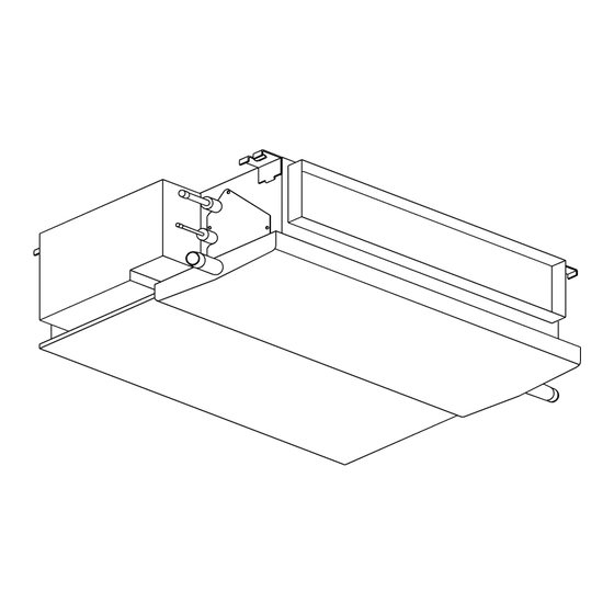
Ceiling Concealed
CONTENTS
SAFETY PRECAUTIONS ·························1
1. FEATURES ···········································3
2. PART NAMES AND FUNCTIONS ········4
3. SPECIFICATION ···································6
4. OUTLINES AND DIMENSIONS············8
5. WIRING DIAGRAM ·······························9
7. TROUBLE SHOOTING ·······················11
8. DISASSEMBLY PROCEDURE ··········· 14
For use with the R410A & R22
2005
Advertisement
Table of Contents

Subscribe to Our Youtube Channel
Related Manuals for Mitsubishi CITY MULTI PEFY Series


Summary of Contents for Mitsubishi CITY MULTI PEFY Series
-
Page 1: Table Of Contents
2005 Air-Conditioners For Building Application TECHNICAL & SERVICE MANUAL Ceiling Concealed Series PEFY <Indoor unit> PEFY-P06NMLU-E Models PEFY-P08NMLU-E PEFY-P12NMLU-E CONTENTS SAFETY PRECAUTIONS ·························1 1. FEATURES ···········································3 2. PART NAMES AND FUNCTIONS ········4 3. SPECIFICATION ···································6 4. OUTLINES AND DIMENSIONS············8 5. WIRING DIAGRAM ·······························9 6. -
Page 2: Safety Precautions
- Inadequate strength may cause the unit to fall down, resulting in is shorted and operated forcibly, or parts other than those specified injuries. by Mitsubishi Electric are used, fire or explosion may result. • Use the specified cables for wiring. Make the connections se- curely so that the outside force of the cable is not applied to the •... - Page 3 Precautions for devices that use Warning: • Note the following when building a heater in the air R410A refrigerant conditioning system. - Leave enough space between units for proper ventilation so that Caution: the indoor unit temperature does not exceed 40˚C when •...
-
Page 4: Features
FEATURES Ceiling Concealed Series PEFY Indoor unit Cooling capacity/Heating capacity Models BTU / h PEFY-P06NMLU-E 1.8 / 2.0 6000 / 6700 PEFY-P08NMLU-E 2.3 / 2.6 8000 / 9000 PEFY-P12NMLU-E 3.5 / 4.0 12000 / 13500... -
Page 5: Part Names And Functions
PART NAMES AND FUNCTIONS G Indoor (Main) Unit Air outlet Air inlet G Remote controller [PAR-21MAA] Once the controls are set, the same operation mode can be repeated by simply pressing the ON/OFF button. [Operation buttons] TEMP. ON/OFF MENU ON/OFF FILTER BACK MONITOR/SET... - Page 6 [Display] CENTRALLY CONTROLLED 1Hr. ON OFF CLOCK CHECK FILTER CHECK MODE TEST RUN STAND BY ERROR CODE FUNCTION NOT AVAILABLE DEFROST TEMP. ON/OFF A Current time/Timer B Centralized control C Timer OFF D Timer indicator E Operation mode: COOL, DRY, AUTO, FAN, HEAT...
-
Page 7: Specification
SPECIFICATION 3-1. Specification PEFY-P-NMLU-E Item Model PEFY -P06NMLU-E PEFY-P08NMLU-E PEFY-P12NMLU-E Power sourse 208/230V, 60Hz Cooling Capacity BTU/h 6000 8000 12000 Heating BTU/h 6700 9000 13500 Height 8-7/8 Dimension Width 31-1/8 Depth 21-21/32 Net weight Airflow rate /min 4.8-5.8-7.9 4.8-5.8-7.9 4.8-5.8-9.5 (Low-Middle-High) 169-205-279 169-205-279... - Page 8 3-2. Electrical parts specifications Model Symbol PEFY-P06NMLU-E PEFY-P08NMLU-E PEFY-P12NMLU-E Parts name Tranrsformer (Primary) 50/60Hz 220-240V (Secondry) (23.5V 0.9A) Room Resistance 0˚C[32˚F]/15kΩ,10˚C[50˚F]/9.6kΩ,20˚C[68˚F]/6.3kΩ,25˚C[77˚F]/5.4kΩ, temperature TH21 30˚C[86˚F]/4.3kΩ,40˚C[104˚F]/3.0kΩ thermistor Liquid pipe Resistance 0˚C[32˚F]/15kΩ,10˚C[50˚F]/9.6kΩ,20˚C[68˚F]/6.3kΩ,25˚C[77˚F]/5.4kΩ, TH22 thermistor 30˚C[86˚F]/4.3kΩ,40˚C[104˚F]/3.0kΩ Gas pipe Resistance 0˚C[32˚F]/15kΩ,10˚C[50˚F]/9.6kΩ,20˚C[68˚F]/6.3kΩ,25˚C[77˚F]/5.4kΩ, TH23 thermistor 30˚C[86˚F]/4.3kΩ,40˚C[104˚F]/3.0kΩ Fuse (Indoor con- FUSE 250V 6.3A...
-
Page 9: Outlines And Dimensions
OUTLINES AND DIMENSIONS PEFY-P06·08·12NMLU-E Unit :mm(in.) -
Page 10: Wiring Diagram
WIRING DIAGRAM PEFY-P06·08·12NMLU-E... -
Page 11: Refrigerant System Diagram
REFRIGERANT SYSTEM DIAGRAM Gas pipe thermistor TH23 Gas pipe Liquid pipe thermistor TH22 Brazed joints Heat exchanger Linear expansion valve Strainer (#100mesh) Strainer (#100mesh) Room temperature thermistor TH21 mm <in.> Capacity PEFY-P06·08·12NMLU-E Item Gas pipe ø12.7<1/2> Liquid pipe ø6.35<1/4>... -
Page 12: Trouble Shooting
TROUBLE SHOOTING 7-1. How to check the parts Parts name Check points Room temperature Disconnect the connector, then measure the resistance using a tester. thermistor (Sorrounding temperature 10°C~30°C[50°F~86°F]) (TH21) Liquid pipe thermistor (TH22) Normal Abnormal Gas pipe thermistor (Refer to the thermistor characteristic graph) Ω... - Page 13 7-2. Setting of address switch Make sure that power source is turning off. Indoor unit control board S W2 SW 3 S W 4 < At delivery (All models)> S W1 S W 4 < At delivery (All models)> 1 2 3 4 5 6 7 8 9 10 0 1 2 3 4 5 6 7 8 9 9 10...
- Page 14 7-3. Setting of Dip-switch (at delivery) Models Dip-SW S W1 SW 2 S W3 S W4 S W5 PEFY- 220V Option P06NMLU-E 240V Standard 1 2 3 4 5 6 7 8 910 1 2 3 4 5 6 1 2 3 4 5 6 7 8 910 1 2 3 1 2 3 S W3...
-
Page 15: Disassembly Procedure
DISASSEMBLY PROCEDURE Be careful on removing heavy parts. 8-1. CONTROL BOX OPERATING PROCEDURE PHOTOS 1.Removing the control box cover fig.1 (1) Remove the fixing screws (two) of the control box (A), and remove the cover. (Fig. 1) *At this stage, the following servicing is possible. 1 Operation and check of the switches (listed below) which are on the control board. - Page 16 Be careful on removing heavy parts. 8-2. FAN and FAN MOTOR OPERATING PROCEDURE PHOTOS 1.Removing the fan casing and sirocco fan. fig.3 (1) Remove the bottom plate 1. (fixing screws : six) (Fig. 3) (2) Remove the fixing screws (three) of the fan casing, and turn it in direction of arrow.
- Page 17 Be careful on removing heavy parts. 8-3. DRAINPAN OPERATING PROCEDURE PHOTOS fig.10 1.Removing the drainpan. (1) Remove the fixing screw (one) of the drainpan.(Fig. 10). (2) Slide the drainpan in the order of arrow 1,2,3, and remove the drainpan. (Fig. 11) fig.11...
- Page 18 Be careful on removing heavy parts. 8-4. LEV,THERMISTOR (Liquid/Gas piping temperature detection) OPERATING PROCEDURE PHOTOS fig.12 1.Removing the LEV. (1) Remove the drainpan with procedure 8-3. (2) Remove the bottom plate 2 (fixing screws : six), and remove the plate.(Fig. 12) (3) Remove the LEV driving motor with a double spanner.
- Page 19 Be careful on removing heavy parts. 8-5. HEAT EXCHANGER OPERATING PROCEDURE PHOTOS fig.15 1.Removing the heat exchanger. (1) Remove the drainpan with procedure 8-3. Heat exchanger cover (2) Remove the bottom plate2 with procedure 8-4. (3) Remove the heat exchanger cover.(fixing screws : four) (Fig.
- Page 20 8-6. CONTROL BOX INSIDE LAYOUT FAN3 Indoor unit X06 X05 Address board contoller board Condenser (for motor) Transmission terminal bed DSA board Power sourse Trans terminal bed 8-7. SENSOR POSITION Gas sensor Liquid sensor...
- Page 22 HEAD OFFICE: MITSUBISHI DENKI BLDG., 2-2-3, MARUNOUCHI, CHIYODA-KU, TOKYO 100-8310, JAPAN Issued in Aug. 2005 HWE05140 New publication, effective Aug. 2005 Printed in Japan Specifications subject to change without notice...
- Page 23 SERVICE PARTS LIST FOR MITSUBISHI ELECTRIC PACKAGED AIR-CONDITIONERS Series PEFY-P NMLU-E • REVISED June 2009 For use with the R410A 0511A INDEX P E F Y - P 0 6 N M L U - E P E F Y - P 0 8 N M L U - E P E F Y - P 1 2 N M L U - E Please change the old catalog (issued July 2005, BWE05110) to this new catalog.
- Page 24 PEFY-P06,P08,P12NMLU-E EXTERNAL PARTS 101.102.103 G : RoHS Apply Only W : RoHS Apply by Running Change Part No. Spec. Dwg. No. Price Part Name 101 R61 Y26 483 W Heat exchanger assy 1 1 1 W265695G25 102 R63 902 936 G Thermistor(gas) NTH3A23-4<TH23>...
- Page 25 PEFY-P06,P08,P12NMLU-E BLOWER PARTS 205. 206 G : RoHS Apply Only W : RoHS Apply by Running Change Part No. Spec. Dwg. No. Price Part Name 201 R63 Y14 140 G Fan base 1 1 1 W267214G01 202 R63 370 130 G Motor suppprt 1 1 1 W234925H06...
- Page 26 PEFY-P06,P08,P12NMLU-E CONTROL BOX PARTS 303. 304 G : RoHS Apply Only W : RoHS Apply by Running Change Part No. Spec. Dwg. No. Price Part Name 301 R63 Y08 715 G Terminal bed <TB2> 1 1 1 P436239X01 302 R63 336 246 G Terminal bed <TB5>,<TB15>...
- Page 27 HEAD OFFICE: TOKYO BLDG., 2-7-3, MARUNOUCHI, CHIYODA-KU, TOKYO 100-8310, JAPAN BWE0511A (20090630)
Need help?
Do you have a question about the CITY MULTI PEFY Series and is the answer not in the manual?
Questions and answers