
Related Manuals for Gendex GX CB-500


Summary of Contents for Gendex GX CB-500
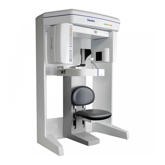
- Page 1 Service Manual Service Manual Service Manual Service Manual Service Manual Cone Beam Volumetric Tomography and Panoramic Dental Imaging System...
- Page 2 No part of this document may be reproduced or transmitted in any form or by any means, electronic or mechanical, for any purpose, ® without prior written permission of Gendex . The information in this document and the product it describes are subject to change without notice.
-
Page 3: Table Of Contents
Table of Contents ABLE OF ONTENTS Chapter 1 - Introduction System Description ...................1-1 Major System Items ..................1-2 About the Operators’ Manual .................1-3 Conventions Used in the User Manual .................. 1-3 Standard Limited Warranty ................1-4 Chapter 2 - Safety Items Important Safety Information .................2-1 Warnings, Cautions, and Notes .................... - Page 4 Table of Contents Chapter 3 - System Controls and Indicators Operator Control Box ..................3-1 Patient Emergency Stop Control ..............3-2 Patient Alignment Panel ..................3-2 System Status Indicators ..................3-2 Chapter 4 - System Startup and Shutdown System Startup ....................4-1 System Shutdown .....................4-1 Chapter 5 - System Assembly Initial Preparation ...................5-1 Required Tools ....................5-1...
- Page 5 Table of Contents Uniformity Test in Landscape Mode ..................8-14 Noise Level Test in Half-Beam Mode .................. 8-15 Uniformity Test in Half-Beam Mode ................... 8-18 PAN Phantom Test ..................8-20 Radiation Output Test ..................8-23 Measured Dose ........................8-23 Interpretation ........................8-24 Chapter 9 - Troubleshooting and Adjustments Detector Pivot Adjustment (Receptor Panel) ..........9-1 IEC IC Command Codes .................9-3...
- Page 6 Table of Contents Chapter 12 - Remote System Import and Export Remote System Import and Export Overview ..........12-1 Remote System Import ...................12-1 Import Installation and Setup ...............12-2 Set Up DICOM Worklist Interface ..................12-2 Set Up Practice Management Interface ................12-4 Import Patient Data ..................12-5 Remote System Export ...................12-6 Export Installation and Setup ...............12-6...
- Page 7 Table of Contents Replaceable Parts - Reference List .............13-12 Accessories ....................13-13 Chapter 14 - Illustrated Parts Breakdown System Assembly ....................14-2 System Assembly Parts List ....................14-3 Overhead Assembly ..................14-4 Overhead Assembly Parts List ....................14-5 Rotation Drive Assembly ................14-6 Rotation Drive Assembly Parts List ..................14-7 X-Ray Source Assembly .................14-8 X-Ray Source Assembly Parts List ..................
- Page 8 Appendix A - iCATVision, iCATTransfer, & RSQM Installation iCATVision ...................... A-1 Laptop Minimum Requirements .....................A-2 Workstation Minimum Requirements ..................A-2 File Structure Setup ........................A-2 Install iCATVision ........................A-3 iCATVision Setup ........................A-4 iCATTransfer ....................A-5 Install iCATTransfer ......................A-5 iCATTransfer Passcode ......................A-6 iCATTransfer Setup ........................A-6 Configure iCATTransfer ......................A-7 Accessing i-CAT®...
-
Page 9: Chapter 1 - Introduction
Chapter Introduction System Description The system is a Cone Beam Volumetric Tomography and Panoramic X-ray device used for dental applications. The system consists of a Scanner and Computer Workstation which is suitable for an in-office environment. This scanning device is an open design that allows Patients to sit upright during a procedure. -
Page 10: Major System Items
Service Manual Gendex GXCB-500 The system consists of a Scanner and Computer Workstation. In order for the system to operate, both the Scanner and Computer Workstation must be turned ON. The system captures data for 3D Skull Reconstruction for the... -
Page 11: About The Operators' Manual
Introduction About the Operators’ Manual This documentation describes the safe and effective operation of the system. The information is intended to provide trained Technologists and Physicians the necessary guidance to operate the system in a safe and effective manner. Conventions Used in the User Manual Keyboard keys are represented in a font. -
Page 12: Standard Limited Warranty
The warranty period is not extended as a result of purchasing any additional parts from Gendex. The original purchaser must promptly notify Gendex in writing if there is a defect in material or workmanship. Written notice in all events must be received by Gendex before expiration of the warranty period. - Page 13 No oral or written information or advice given by Gendex, its agents or employees shall create a warranty or in any way increase the...
- Page 14 Service Manual Gendex GXCB-500 G990710 30 June 2008...
-
Page 15: Chapter 2 - Safety Items
Chapter Safety Items Important Safety Information Gendex designs its products to meet stringent safety standards. However, to maintain the safety of Operators and Patients, you must operate the equipment correctly and properly and ensure the equipment is properly maintained. It is essential to follow all safety instructions, warnings, and cautions specified in this manual to ensure the safety of Patients and Operators. -
Page 16: Safety Precautions
Service Manual Gendex GXCB-500 Advisories are used to defined information for the ADVISORY: operator regarding advice towards use of the device or a process. Notes are used to highlight important or unusual points to be NOTE: brought to the attention of the operator. -
Page 17: Explosion Hazard
Safety Items WARNING WARNING In the event of an electrical fire, only use extinguishers that are labelled for that purpose. Using water or other liquids on an electrical fire can lead to fatal or other serious personal injury. WARNING WARNING In the event of an electrical fire, to reduce the risk of electrical shock, try to isolate the equipment from the electric source before attempting to extinguish the fire. -
Page 18: Laser Beam Hazards
Service Manual Gendex GXCB-500 Collision System The Gantry motor is programmed to operate at a rotational force of < = 15 lbf (66.7N). Interference or incidental contact with the Gantry during rotation, which results in an interruption in Gantry motion, will be detected and trigger a system stall event. -
Page 19: Radiation Safety
Safety Items Radiation Safety X-rays are dangerous to both operator and others in the vicinity unless established safe exposure procedures are strictly observed. Use the following safety measures to ensure safety to the Patient and Operator. The useful and scattered beams can produce serious or fatal bodily injuries to Patients and persons in the surrounding area if used by an unskilled operator. -
Page 20: System Safety Devices
Service Manual Gendex GXCB-500 System Safety Devices Emergency Stops This manual contains instructions for safe operation of this dental X- ray System. In the event of an emergency (any moving component collides with any parts of the equipment or items in the environment,... -
Page 21: Sample Site Plan
Safety Items Sample Site Plan Below are two typical scanning room layouts that illustrate the system interconnect for the Warning System, Operator Control Box (Emergency Stop) and Interlock System which are all describe above. Room layouts must provide a means for audio and visual communication between the Operator and Patient. -
Page 22: Interlock And Warning System Schematic
Service Manual Gendex GXCB-500 Warning System Cable 50 ft. [15.2m] (if used) Patient Scanner Emergency Stop Box with Warning 10 ft. [3m] Cable Light or Alarm (not supplied) Hallway CAT 5 Ethernet Cable 50 ft. (15.2m) Computer Workstation Interlock Cable Operator Control Box 50 ft. -
Page 23: Cabling Requirements
Safety Items Cabling Requirements System cabling connections must be installed away from walkways and doorways. It is recommended to run cabling along wall perimeters. If there is a chance of mechanical damage due to the cable location, then the use of conduit or other means of protection should be considered. -
Page 24: System Labels
Service Manual Gendex GXCB-500 System Labels The following labels are attached to the system. Caution Location: Multiple locations to indicate the operator should exercise caution when working near this area and should consult written instructions. Warning Location: Rear of Overhead to indicate Electrical Hazard, Authorized Personnel only. - Page 25 Safety Items Caution: Laser Radiation Do not stare into beam Location: Front center of Gantry and Source Panel. Caution: Laser Radiation Do not stare into visible light beam Location: Alignment Panel. Caution: This X-ray unit may be dangerous to patient and operator unless safe exposure factors and operating procedure are observed.
- Page 26 Service Manual Gendex GXCB-500 Caution: Maximum lifting capacity Location: Patient Chair, below rear seat pad. Caution: Maximum lifting capacity Location: Patient Chair, above rear seat pad. Chair Instruction Label Insert seat fully to line Location: Patient Chair, behind seat pad.
-
Page 27: Error Messages
Safety Items Error Messages The following are error messages that the system may display. If problems persist after performing the indicated action or actions in the message, call Service. G990710 30 June 2008 2-13... - Page 28 Service Manual Gendex GXCB-500 G990710 30 June 2008 2-14...
-
Page 29: Chapter 3 - System Controls And Indicators
Chapter System Controls and Indicators Controls and Indicators are found on the following system units: Operator Control Box • Patient Alignment Panel • Patient Emergency Stop Control • System Status Indicators • Operator Control Box ON powers the Scanner and the POWER indicator lights to show that the device is ON. -
Page 30: Patient Emergency Stop Control
Service Manual Gendex GXCB-500 Patient Emergency Stop Control PATIENT EMERGENCY STOP allows the Patient to halt all X-ray and scanning activities by pressing the button. The Emergency Stop Control can either be hung from the head support mechanism or held in the Patient’s hand as desired. -
Page 31: Chapter 4 - System Startup And Shutdown
Chapter System Startup and Shutdown It is recommended to do a System Shutdown each day at the close of business. The system is available for use immediately after System Startup, no device warmup is required. System Startup The System includes the Scanner and a Computer Workstation. Both units must be ON to function properly. - Page 32 Service Manual Gendex GXCB-500 If changes were made to a case study, the following dialog box appears. a. Click Yes. The dialog box closes. b. Click Create New Workup. c. Enter a name for new Workup in the Workup Name: field.
-
Page 33: Chapter 5 - System Assembly
Chapter System Assembly Initial Preparation Before beginning system assembly, please review the Safety chapter to familiarize yourself with the safety precautions related to the system. Required Tools Spirit Level Tool Kit (supplied with unit) 3/16 inch T-Handle Allen Wrench • 1/4 inch Nut Driver •... -
Page 34: Inventory Of Unit Items
Service Manual Gendex GXCB-500 Inventory of Unit Items The following system items are included in the shipping crate. 1. Gantry 2. Rear Scatter Shield 3. Chair Assembly 4. Wall Mount Assembly 5. Tube Head Assembly Box Tube Head Assembly •... - Page 35 System Assembly Interlock Cable Warning System Cable CAT -5 Ethernet Cable Hospital Grade Power Cable Patient E-Stop with Holster Phantoms • Cylinder Phantom Line Pair Phantom i-PAN Phantom Water Phantom Assembly Miscellaneous Accessories • Calibration platform Head Rest Kit Chin Rest Chin Cups (2) Bite Tip Holders (2) Bite Tips (25)
-
Page 36: System Assembly
Service Manual Gendex GXCB-500 System Assembly There are two methods used for shipping the device; assembled and non-assembled. Start with step one for the non-assembled scanner. Start with step 9 for scanners that are shipped assembled. Before moving the System into place, ensure that the area is clean and that there is ample room to work. - Page 37 System Assembly Remove top cover (six mounting screws). 3/32 WARNING This devices requires a two person lift. Failure to comply may cause bodily injury. Two adults are required to assemble this device. CAUTION CAUTION Use extreme care not to scratch Overhead Assembly when mounting unit onto Leg Assemblies.
- Page 38 Service Manual Gendex GXCB-500 Ensure the pins on rear of the Overhead device are seated into the holes on Leg Assemblies. When seated properly, Overhead device locks into place. To ensure safety, the Overhead should still be supported by an assistant until mounted.
- Page 39 System Assembly From top of unit, secure Overhead with mounting hardware, two SHCS 1/4-20 x 5/8 long with 1/4” Split Washers, both sides. 3/16 CAUTION CAUTION Care must be taken when sliding the device into place. To prevent the unit from scratching the floor surface, place the four Glides under the device feet.
- Page 40 Service Manual Gendex GXCB-500 WARNING The Receptor Assembly requires a two person lift. Failure to comply may cause bodily injury. Locate Receptor Assembly and remove packing material. 3/32 14. Remove assembly cover from unit (4 outer screws). 3/32 With an assistant, mount the...
- Page 41 System Assembly CAUTION CAUTION When mating connectors, do not force-fit connectors together. All connectors are color coded and keyed to prevent improper mating. 19. Connect together the red/white connectors (grey wires) as shown. 20. Rotate into position, aligning red dots, then press to lock the gold connector (grey wire) onto the keyed Power...
- Page 42 Service Manual Gendex GXCB-500 Connect green connector (grey wire) to assembly as shown). Do not connect small white connector (grey wire). To be used for future use. 27. Dress cables using flexible plastic wire wrap. Install Receptor cover. 29. Attach mounting screws on top and bottom of cover.
- Page 43 System Assembly Remove red Shipping Plate. Do NOT discard mounting hardware (quantity 8) or Shipping 3/16 Plate. Long screws used for Receptor Assembly mounting and short screws for Source Assembly. Locate X-ray Source Assembly and remove from packing material. 32. Place assembly on clean surface.
- Page 44 Service Manual Gendex GXCB-500 Carefully detach and move inner Source Cover a few inches away from assembly. 36. Remove ribbon cable from Beam Limiter Assembly by depressing connector locking tab. Using very little force, slowly rotate gantry, counterclockwise. Stop the...
- Page 45 System Assembly WARNING The X-ray Source Assembly requires a two person lift. Failure to comply may cause bodily injury. With an assistant, align X-ray Source Assembly mounting pins. 40. Attach assembly using the four mounting screws previously removed from red Shipping Plate along with four split washers.
- Page 46 Service Manual Gendex GXCB-500 Attach ribbon cable back to the Beam Limiter Assembly. Slide Adjustment Panel Cover into place, onto top mounting notches. 48. Mount outer cover onto mounting notches, over panel cover. 49. Attach covers with the four hex mounting screws at the bottom of assembly.
- Page 47 System Assembly Install Mounting Bar on wall, centered behind the unit. The height should be approximately 66 ½ to 68 inches [169 to 173 cm] from the floor to the center of the Mounting Bar. However, this may vary, so you may want to put the “L”...
- Page 48 Service Manual Gendex GXCB-500 Connect Power Cable to AC POWER IN connector on rear of Overhead Panel. 59. Ensure the Power Circuit Breaker on the Overhead rear panel is set to the OFF position. The OFF position is the O symbol.
-
Page 49: Chapter 6 - Leveling And Alignment
Chapter Leveling and Alignment Level Gantry To achieve optimal performance, it is imperative that the Gantry be properly leveled. Leveling the Gantry: 1. Remove top cover (6 screws). 3/32 2. Remove shielding cover. 3. Unit must be leveled from side- to-side and front-to-back. - Page 50 Service Manual Gendex GXCB-500 Level Overhead Gear using 1/4” Hex Driver to adjust the front Gantry feet. 1/4” Driver Adjust the rear Gantry feet using the 1/2” Open-ended Wrench. Ensure levelness of NOTE: Overhead Gear is measured Front-to-Back and Side-to- Side.
- Page 51 Leveling and Alignment Replace shielding cover. Replace top cover (6 screws). 3/32 9. Now that the device is positioned and leveled, tighten wall bracket at top rear of gantry. Switch the Power Circuit Breaker which is located on the Overhead rear panel to ON. The ON position is the l symbol.
-
Page 52: Patient Chair Alignment
Service Manual Gendex GXCB-500 Patient Chair Alignment To acquire quality images, the chair must be accurately leveled and aligned. Leveling Patient Chair: 1. From the Acquisition computer, double click the Calibration icon. The Calibration screen is displayed and the device moves to the home position. - Page 53 Leveling and Alignment 5. On the Calibration screen, click the Vertical Chair Line checkbox and ensure slider is at 0 position. 6. Click Preview. A dialog is displayed. 7. Click OK to start the scan process. WARNING WARNING The X-ray device may be dangerous to the Patient and operator if you do not observe and follow the safe exposure factors and operating instructions.
- Page 54 Service Manual Gendex GXCB-500 Centering Patient Chair: 10. On the Calibration screen: a. Move slider to 90 position and perform a Preview. b. Verify that the vertical pin falls within the blue shaded area. If aligned, go to step 17.
- Page 55 Leveling and Alignment 13. Repeat Preview and Chair Assembly adjustment (step 12) as needed until pin is within blue shaded area on Preview scan. 14. When pin falls within the blue shaded area at both 0 and 90 tighten Chair mounting bolts. Tightening the left bolt first (when facing rear of Scanner) NOTE: may help prevent the Chair Assembly from shifting.
-
Page 56: Laser Alignments
Service Manual Gendex GXCB-500 Laser Alignments The scanner has two alignment lasers. Centerline Laser - located on the front of Overhead Gantry • Crosshair Laser - housed inside the X-ray Source Assembly. • WARNING Do not stare into laser. Severe personal injury (blindness) may result. - Page 57 Leveling and Alignment Right-to-Left Adjustment: 1. Loosen laser assembly set screw which allows the assembly to rotate. 2. Press the ALIGNMENT LIGHT button on the Operator 5/32 Panel. The laser lights for approximately two minutes. While the laser is lit, manually rotate the laser assembly until it is aligned with the center line on the Chair Center Locator.
- Page 58 Service Manual Gendex GXCB-500 Laser Line Sharpness Adjustment: 1. Loosen laser pointer lens set screw. 2. Press the ALIGNMENT LIGHT button on the Operator Panel. 1/16 3. Manually rotate laser pointer lens with your finger tip until laser line is thin and sharp.
-
Page 59: Adjust Crosshair Laser
Leveling and Alignment Adjust Crosshair Laser When the ALIGNMENT LIGHT button is pressed, the Crosshair Laser shines from the X-ray Source Panel and appears on the Receptor Panel. The crosshairs should appear directly in line with the four notches on the panel cover, as shown below. There are three types of laser adjustments: Horizontal Line up/down •... - Page 60 Service Manual Gendex GXCB-500 Horizontal Line Adjustment: 2. Check height of horizontal crosshair line with panel cover notches. NOTCH NOTCH To move horizontal laser line up/down turn adjustment screw (shown): Clockwise - moves line up • CCW - moves line down •...
- Page 61 Leveling and Alignment To move vertical laser line forward/back loosen the two 5/32 mounting screws (shown). The bracket pivots on the center mounting screw which moves the vertical laser line. 6. Tighten both screws when properly aligned. Rotate Crosshair Laser Lines: 7.
-
Page 62: Head Holder Alignment
Service Manual Gendex GXCB-500 Head Holder Alignment Ensure that the Laser Alignments have been completed NOTE: before beginning this procedure. If head support is installed, loosen locking knob LASER and remove head support. LINE 2. Slide head holder into place. -
Page 63: Chapter 7 - Calibration
Chapter Calibration The Panel, Collimators, and Geometry Calibrations can be conducted by the Owner / Operator of the device. It is recommended that the Panel Calibration be performed once a week. Panel Calibration The Panel Calibration is performed for both Portrait and Landscape positions. - Page 64 Service Manual Gendex GXCB-500 The Calibration screen is displayed. 3. Click the Calibrate button (top) in the Panel field. WARNING The X-ray device may be dangerous to the Patient and operator if you do not observe and follow the operating instructions. Do not operate this system unless you have received training to perform a procedure.
-
Page 65: Collimators Calibration
Calibration Collimators Calibration It is recommended to perform the Collimators Calibration annually to ensure optimal image quality. This calibration is also necessary if a mechancial adjustment is made to the Beam Limiter or if image quality has degraded. The Panel Calibration must be performed prior to this. -
Page 66: Geometry Calibration
Service Manual Gendex GXCB-500 Geometry Calibration It is recommended to perform the Geometry Calibration annually to ensure optimal image quality or if the image quality is degraded. The Panel Calibration must be performed prior to this. The Geometry Calibration runs in both Portrait and Landscape positions and takes about 12 to 15 minutes to complete. - Page 67 Calibration 17. Click the Preview button which is located at the bottom of the Calibration screen. WARNING WARNING The X-ray device may be dangerous to the Patient and operator if you do not observe and follow the operating instructions. Do not operate this system unless you have received training to perform a procedure.
- Page 68 Service Manual Gendex GXCB-500 23. Select both the Landscape and Portrait calibrate modes. WARNING WARNING The X-ray device may be dangerous to the Patient and operator if you do not observe and follow the operating instructions. Do not operate this system unless you have received training to perform a procedure.
- Page 69 Calibration Beads detected = 12, Beads valid = 12 28. At the prompt, press Scan on the Control Box, to start the Portrait Scan. 29. During the Portrait Scan, ensure the following is displayed: Beads detected = 8, Beads valid = 8 Check to ensure that all beads are intact on the BB Phantom, NOTE: if the calibration did not detect a bead at a certain location.
- Page 70 Service Manual Gendex GXCB-500 G990710 30 June 2008...
-
Page 71: Chapter 8 - Quality Assurance
Chapter Quality Assurance QA Phantom Test The following Quality Assurance Tests can be conducted by the Owner / Operator of the device. It is recommended that the System Quality Assurance be performed annually or if image quality becomes degraded. For this purpose, the following procedures are provided with a QA Phantom Test and QA Water Test. - Page 72 4. Center the QA Phantom on the platform with the Air Hole positioned at the left front of the Gantry (shown below). LDPE ACRYLIC AIR HOLE TEFLON 5. Start the test by selecting File > New Patient from the Main menu.
- Page 73 11. The Phantom Platform must appear below the Field of View and the Phantom must be centered. Adjust the Phantom Platform to achieve the proper height. 12. To move the phantom to the right or left, use the Back / Front feature.
- Page 74 17. The following preview screen is displayed.
-
Page 75: Line Pair Evaluation
Line Pair Evaluation 18. Access the QA Test images for evaluation by double clicking Coronal View (bottom image, 2 from the right). 19. The image below is displayed. In the top-right corner view, slide the Vertical and Horizontal lines to the Line Pairs centers as shown below. - Page 76 20. Zoom Line Pair image (top- left). To zoom, start at the upper right corner of image and hold down left mouse button and drag cursor across the image. 21. Right click the image and select Set Filter > Hard. 22.
-
Page 77: Distance Measurement Test
Distance Measurement Test To ensure measurement accuracy, this procedure verifies that the Distance tool is functioning properly. 24. Right click view and select Distance. 25. Drag the Distance cursor to draw a line from the outside line of set 18 to the outside line of set 12, as shown. - Page 78 29. From the preview scan, access the QA Test images for evaluation by double clicking Coronal View. (bottom image, from the right). 30. In the top-right image of the Coronal View, slide the Horizontal line up to bring the Housfield Unit centers into view. In the top- left image, slide the Vertical and Horizontal lines to the Hounsfield Unit centers as shown below.
- Page 79 c. Move the position of the slice to the middle of the phantom on the top-left image as shown below. 32. Right click the image and select HU Statistics from the menu (also, right click to turn off HU Statistics). 33.
-
Page 80: Qa Water Phantom Test
QA Water Phantom Test The Water Phantom Test is a noise level and uniformity test which uses both water and air as a measuring tool. It is important that the Water Phantom provided is used for these tests. 1. Remove Chin Cup and insert Phantom Platform. 2. - Page 81 Enter Water Calibration in the First Name field and Noise Test Landscape in the Patient ID field. 8. Click OK to close the Patient Information box. 9. From the Volume tab select the following: Size of Reconstruction Volume: Dia 8.5 - H 8.5 cm Resolution: 0.4 voxel WARNING WARNING...
- Page 82 16. At the bottomof the top-right image scale, click and hold the ● cursor on the symbol. The slice thickness is displayed. Slide the cursor up to change the value to 0.4 mm. 17. In the top-left screen, right click the image area and select HU Statistics from the menu (also, right click to turn off HU Statistics).
- Page 83 20. In the top-right screen, move the red dotted line upward, so the line is located at the top of the phantom, above the water level. 21. In the top-left screen, right click the image area and select HU Statistics from the menu (also, right click to turn off HU Statistics).
-
Page 84: Uniformity Test In Landscape Mode
Uniformity Test in Landscape Mode The Uniformity Test is to ensure that image density measurements are consistent in all areas within the Field of View. 24. Move the red, green, and blue dotted lines to the center of the water (all screens) as shown below. Use the Center Line Positioning tool to make these adjustments 25. -
Page 85: Noise Level Test In Half-Beam Mode
28. Note and record the Mean and SD values of the center ROI. Measured Upper Upper Lower Lower Center Values Left Right Left Right Mean Subtract each Mean Value from the Mean Value of the center ROI. If any difference is greater than 90, make sure phantom is correctly centered in FOV and re-measure. - Page 86 36. At the Contourline prompt, select No and Cancel. 37. Access the HU measurement image for evaluation by double clicking Coronal View (bottom image, 2 from the right). 38. In the top-right screen, slide the Horizontal line to the middle of the water height.
- Page 87 40. In the top-left image, right click the image area and select HU Statistics from the menu (also, right click to turn off HU Statistics). Use the Region Tool to define a ROI (Region of Interest) in the center of Water, as shown above. HU Area (box size) should be approximately 400.0 mm 41.
-
Page 88: Uniformity Test In Half-Beam Mode
Record the air HU Mean value in the table below. Measured Values Water Mean Expected Values 0 (-70 to + 70) -1000 (-930 to -1000) 45. Right click the HU measurement and select Remove Measurement. Uniformity Test in Half-Beam Mode The Uniformity Test is to ensure that image density measurements are consistent in all areas within the Field of View. - Page 89 48. Note and record the Mean and SD values of the four regions. See chart below. 49. After recording values, a fifth ROI is required from the center of the water area. The fifth measurement replaces the first measurement, since four measurements are the limit. 50.
-
Page 90: Pan Phantom Test
PAN Phantom Test PAN Phantom Test is used to validate the PAN scan data capture. To perform a PAN Phantom Test: 1. Prepare the Bite Tip by inserting the narrow edges of the Bite Tip down into the Bite Tip Holder uprights. Then turn the Bite Tip a 1/4 turn to lock into place. - Page 91 Enter PAN Test in the First Name field and QA in the Patient ID field. 7. Click OK to close the Patient Information box. 8. Click the Pan tab in the Acquisition window and select, Exposure: Large 9. Click the Capture button to start the test. WARNING WARNING The X-ray device may be dangerous to the Patient and operator if...
- Page 92 13. The PAN scan runs a few minutes and then displays the reconstructed image. 14. Adjust the Brightness/Contrast by dragging the cursor across the image (vertical/horizontal). All seven metal balls should become visible as shown below. Good Image Quality 15. The image above is an example of a system properly aligned for PAN scanning.
-
Page 93: Radiation Output Test
Radiation Output Test It is recommended that a check of the kVp(eff) and Radiation Output of the X-ray source be performed annually by a qualified Physicist. The incident Absorbed Dose at the detector may be measured using a dosimeter. Tests are performed to assess output value and to check for tube output consistency and timer accuracy. -
Page 94: Interpretation
Interpretation 1. The dose per frame at the detector may be calculated by: Dose per frame at Detector = Dose at Detector / Number of Frames Where Number of Frames = 309 for 8.9 second scan = 619 for 23.0 second scan 2. -
Page 95: Chapter 9 - Troubleshooting And Adjustments
Chapter Troubleshooting and Adjustments Detector Pivot Adjustment (Receptor Panel) The Receptor Panel must be on level-plane as the Source Panel in both the Portrait and Landscape positions. The Geometric Calibration shows if the Receptor Panel is properly aligned. Checking Detector Pivot: 1. - Page 96 Service Manual Gendex GXCB-500 Remove two mounting screws from the top and bottom and remove Receptor Cover. 3/32 On the Receptor Assembly, loosen the two panel mounting screws. 3/16 4. One Leveling Screw is used to adjust the Detector Pivot for both...
-
Page 97: Iec Ic Command Codes
Troubleshooting and Adjustments IEC IC Command Codes Home Commands Home Beam Limiter (HB = 0, 0, 0, 0 All four shutters completely open) HFR Homes gantry and sets position to 100000 Homes gantry and sets position to 1500 HSR Quick home check if the machine is already homed Movement Commands Move Beam Limiter right left top bottom Enter command as MB X X X X where X is:... -
Page 98: Read Commands
Service Manual Gendex GXCB-500 MRD Target Speed. Enter command as MRD X X where X is: Target: between -40 - 430 degrees (home position is equal to zero degrees - absolute) Type: between 1000 - 65000 Example: MRD 180 1000... - Page 99 Troubleshooting and Adjustments 64 Rotation Optical Switch Status 128 Rotation Limit Switch 256 Rotation Start of Travel Status 512 Rotation End of Travel Status 1024 Platform Start of Travel Status 2048 Platform End of Travel Status 4096 Door Signal 8192 Panel Horizontal (Landscape) 16384 Panel Vertical (Portrait) 32768 Machine Power Status 65536 Right Shutter Limit Switch...
-
Page 100: X-Ray Commands
Service Manual Gendex GXCB-500 Read X-ray Setup See SX command for argument description. 0 = 120KV Range 1 = 90 KV Range If no parameter is entered, then the command assumes 0. Sets platform position - Sets the counts of the platform. -
Page 101: Miscellaneous Commands
Troubleshooting and Adjustments Miscellaneous Commands Read System Information Machine Version, Hardware Version, Software Version Beam Limiter Version, Machine Serial Number Cancel Scan. Cancels a scan. Clear Exception Register. Clears all exceptions except for error that require initialization. WSB Enable Scan Button. Enables the scan button to initiate a scan. - Page 102 Service Manual Gendex GXCB-500 G990710 30 June 2008...
-
Page 103: Chapter 10 - Wall Mount Control Box
Chapter Wall Mount Control Box The Control Box is configured for desktop usage but can be modified for wall mounting access. Desktop Wall Mounted Wall Mounted (cable exposed) (cable inside wall) Wall Mount with Cable Exposed Control Box cable is to be disconnected from rear of Overhead Panel. - Page 104 Service Manual Gendex GXCB-500 Using a fine tip Phillips screwdriver, loosen four mounting screws on rear of Control Box. Rotate Control Box face plate 90 , being careful not to over extend the ribbon cable. Tighten four mounting screws. G990710 30 June 2008...
- Page 105 Wall Mount Control Box Mount Wall Bracket, using supplied mounting hardware (3 places). 6. Hang Control Box onto wall mount bracket. The Control Box can be lifted from the wall for mobility. For a stationary mount see next procedure. For a Stationary Mount 7.
-
Page 106: Wall Mount With Cable Inside Wall
Service Manual Gendex GXCB-500 Wall Mount with Cable Inside Wall Control Box cable is to be disconnected from rear of Overhead Panel. Using a fine tip Phillips screwdriver, loosen four mounting screws on rear of Control Box. lift the face panel from... - Page 107 Wall Mount Control Box Disconnect the Emergency Stop wires by simply pulling the black connectors apart. 5. Disconnect Ribbon Cable by pulling the black and red connectors apart. Remove pin assembly from red connector. Snap-off white plastic cap from red connector. G990710 30 June 2008 10-5...
- Page 108 Service Manual Gendex GXCB-500 Loosen and remove plastic retaining nut from strain relief. 9. Remove black insert from base. 10. Remove cable from Control Box by carefully feeding connectors thru the access hole. Protect wires and connectors by wrapping them in electrical tape if feeding this end thru the wall.
- Page 109 Wall Mount Control Box Snap-on white plastic cap to red connector. Insert pin assembly into red connector. Connect black connectors. 18. Connect ribbon cable. Ensure that the white cap on the red connector and the smooth side of the black ribbon connector are facing up as shown.
- Page 110 Service Manual Gendex GXCB-500 Secure Front Panel to the base by tightening the four mounting screws. To secure the Control Box to the wall, draw center marks in the two tab slots at the rear of the base. 21. Drill two 3/32” pilot holes.
-
Page 111: Chapter 11 - Networking Support Setup
Chapter Networking Support Setup Networking Support Overview Networking support within VisionQ and standalone Vision creates a convenient mechanism for sharing image data within an office or clinic. Using network storage provided and maintained by the customer, system software monitors the connection and allows scanning to proceed even if the network is temporarily broken. -
Page 112: Network Support Installation/Setup
Service Manual Gendex GXCB-500 Note that changes made to studies on the network by a standalone Vision are not transferred back to the VisionQ local disk. VisionQ Vision Standalone Image Root Folder Image Root Folder Dicom, CD, projections Workups, Reports,... -
Page 113: Configure Sweeper Service
Networking Support Setup Configure Sweeper Service 1. Access Control Panel > Administrative Tools > Services and double-click Sweeper Service. 2. On General tab, confirm Startup type is set to Automatic. 3. Click Log On tab: a. Click This account radio button. b. -
Page 114: Migrate From Standalone To Server
Service Manual Gendex GXCB-500 c. Click OK. Migrate from Standalone to Server NOTE: Perform this procedure only if upgrading or migrating from • an existing standalone setup. If the existing network setup shares a portion of the local • disk of theVisionQ computer, it is still considered standalone and this procedure should be followed. -
Page 115: Change Image Root Folder
Networking Support Setup 3. Using Windows Explorer, navigate to the Image Root Folder and delete any files named proj0000.raw, proj0001.raw, ..., proj2000.raw. 4. If a folder named bak is present in the Image Root Folder, the proj0000.raw files in it, as well as the bak folder itself, can be deleted. -
Page 116: Sweeper Service
Service Manual Gendex GXCB-500 Sweeper Service The Sweeper service starts automatically on system power-up and stops on system shutdown. It copies any changed files from the local disk (C:\LocalRoot) to the network Image Root (but only if the local file is bigger than its network counterpart.) It retries failed transfers when the network is up. -
Page 117: Network Failures
Networking Support Setup The Status screen allows the user to start/stop and pause/resume the Sweeper service. It displays the Sweeper log file C:\Sweeper.log, extracts status from the log, and displays it at the bottom of the screen. It reduces to a system tray icon showing the Sweeper state and a tooltip with the current status. -
Page 118: Network Fails During Operations
Service Manual Gendex GXCB-500 Fallback Operations For VisionQ If there is no network access for VisionQ, the best approach is to fix the network. When the network is restored, click Retry on the No Network Access screen and continue work as usual. -
Page 119: Limitations Of Networking Support
Networking Support Setup Try to restore the network. If the network can be restored, operations can continue. If the network cannot be quickly restored and scanning must continue, new scans will be safely stored locally, but will not be transferred to the server until the connection is restored. Therefore, new scans will not appear on the Study list, which will remain blank. - Page 120 Service Manual Gendex GXCB-500 G990710 30 June 2008 11-10...
-
Page 121: Chapter 12 - Remote System Import And Export
Chapter Remote System Import and Export Remote System Import and Export Overview The VisionQ Remote Service application enables the import of patient data from a remote system to Vision Q and enables the export of DICOM images to a remote system from VisionQ. This service functions to reduce data entry redundancy and to synchronize the output generated by VisionQ to a remote system once the study acquisition is completed. -
Page 122: Import Installation And Setup
Service Manual Gendex GXCB-500 (2) Request issued (3) Request received VisionQ PDI Service Class User (4) Patient data sent Remote (5) Response received Server (1) “Process” command issued Import Installation and Setup If the PDI.dll has not been installed, place the PDI.dll in the same folder where the VisionQ.exe resides. - Page 123 Remote System Import and Export 3. Click Import. The Patient Importer screen is displayed. 4. Click Config. 5. Enter Station name, IP Address, AE Title, and Port number for the remote server from where files are to be imported. 6. Click Save, and then Close. 7.
-
Page 124: Set Up Practice Management Interface
Service Manual Gendex GXCB-500 The Options button on the Patient Importer window enables NOTE: setting of the date format and the AE title for the local Acquisition computer, and enabling auto process. These settings are optional and do not have to be changed. -
Page 125: Import Patient Data
Remote System Import and Export Import Patient Data 1. From the VisionQ Main menu, select File > New Patient. 2. Click Import. 3. On the Patient Importer screen, click Process. Patient data is retrieved from the remote system and listed at the bottom of the screen. -
Page 126: Remote System Export
Service Manual Gendex GXCB-500 Remote System Export VisionQ enables DICOM images to be transferred from the VisionQ to a remote system, such as a Picture Archive and Communications System (PACS). The Remote Service Send Module (RSSM) enables the transfer using DICOM storage protocol (C-STORE). RSSM continuously monitors the local folder that is setup to receive the images to be exported. - Page 127 Remote System Import and Export 2. Double-click RSSM.exe. The DICOM Send Module is displayed. 3. Click Options. 4. Click Browse in Source image folder section and browse to the folder where the DICOM files are to be placed for export. Create a new folder if desired.
-
Page 128: Rssm Log
Service Manual Gendex GXCB-500 b. Click Save. c. Click Test to perform DICOM validation (C-ECHO) to check whether the remote server is accessible. 6. Click Browse in the Log file folder section and browse to the folder where the RSSM log file is to reside. -
Page 129: Send Patient Data To A Remote System
Remote System Import and Export The log can also be accessed by selecting Show. This displays the DICOM Send Module with the following options: Options - Used to set date format. • View Log - Displays RSSM log. • Clear Log - Clears RSSM log of all previous activity. •... - Page 130 Service Manual Gendex GXCB-500 4. Check the RSSM log to determine status of the last transmitted file. If file did not transfer successfully, investigate the cause, such as a network failure to the remote system and correct the problem. If the file no longer needs to be transferred, click Yes to overwrite the previous session.
-
Page 131: Chapter 13 - Product Information
Chapter Product Information Technical Specifications X-ray Source Tube Voltage: 120 kVp (eff) Tube Current: 3-7 mA Voltage Wave Shape: Constant Potential Focal Spot: 0.0197 inches (0.5 mm) Duty Cycle: Source to Sensor distance: 28.1 inches (71.4 cm) Source to Patient distance*:19.5 inches (49.53 cm) (center of rotation) * The patient must be properly positioned in the Head Support Positioner Mechanism for each patient for all applications in order to have the focal spot to skin distance as large as possible. -
Page 132: Power Requirements
Service Manual Gendex GXCB-500 Gray Scale: 14 bit Voxel Size: 0.4/0.3/0.25/0.2/.125 mm Image Acquisition: Single 360 degree rotation (maximum) Scan Time: 23.0/8.9 seconds Field of View: (standard) 8 cm x 8 cm Extended Field of View: (EDS) 14 cm diameter x 8 cm height Note: Maximum values can be collimated down. -
Page 133: Weight
Product Information U0 - U1 Where: U0 is the no-load Mains Voltage U1 is the Mains Voltage under load. I1 is the Mains Current under load. Circuit Breaker Apparent Assembly Ressistance 100VAC 101.9VAC 98.1VAC 7.03A 0.54ohms 115VAC 115.1VAC 111.2VAC 6.10A 0.64ohms 200VAC 200.5VAC... -
Page 134: Environmental Specifications
Service Manual Gendex GXCB-500 Environmental Specifications Operating 50 to 95 degrees Fahrenheit (10 to 35 degrees Celsius) 10% to 90% Relative Humidity, non-condensing Transportation and Storage -4 to 158 degrees Fahrenheit (-20 to 70 degrees Celsius) 10% to 90% Relative Humidity, non-condensing... -
Page 135: Patient Support Chair
Product Information Patient Support Chair Overall dimensions: 28.5"d x 24”w x 43”h (72.4 cm x 61 cm x 109.2 cm) Weight: 125 lbs (56.7 kg) Seat height adjustment: 14” to 29” (35.65 cm to 73.7 cm) Maximum patient weight: 400 lbs (181 kg) Complies with IEC 60601-2-32:1994 Disposal Follow local regulations on disposal of waste parts. -
Page 136: Electromagnetic Or Other Interference (Emissions And Immunity)
Service Manual Gendex GXCB-500 Electromagnetic or other Interference (Emissions and Immunity) The System was tested and found to comply with the limits for Class B equipment, pursuant to IEC 60601-1-2. These limits are designed to provide reasonable protection against harmful interference in a commercial environment. - Page 137 Product Information The System is intended for use in an electromagnetic environment specified below. The Customer or User should ensure that the system is used in such an environment. Emission Test Compliance Electrostatic Environment - Guidance Radiated RF This Scanning System is intended for use in an IEC 61000-4-3 electromagnetic environment in which radiated disturbances are controlled.
-
Page 138: Equipment Standards
Service Manual Gendex GXCB-500 Use only the interface cables provided with the System. Using other interface cables may exceed the limits of Class B equipment, pursuant to IEC 60601-1-2. Equipment Standards The System was tested and/or evaluated against and found... -
Page 139: Preventive Maintenance Schedule - For Owner / User
Product Information Preventive Maintenance Schedule - for Owner / User Daily: Routine Dusting - all surfaces Monthly: Clean all surfaces and check for failed/faulty indicator lights. Yearly: Check for satisfactory image quality. IT IS THE RESPONSIBILITY OF THE USER TO INSURE THAT THE EQUIPMENT IS MAINTAINED IN COMPLIANCE WITH THE MANUFACTURER'S RECOMMENDED MAINTENANCE SCHEDULE. -
Page 140: Cleaning
Service Manual Gendex GXCB-500 Cleaning Cleaning the equipment frequently, especially if corroding chemicals are present is a function of the Operator. Unless otherwise instructed, use a cloth moistened with warm water and mild soap. Do not use strong cleaners and solvents as these may damage the finish. - Page 141 Product Information Check Laser Alignments Check Centerline Alignment (using Chair Center Locator) Check Crosshair Laser (align with notches on Receptor Panel Cover) Inspect Tube Housing Components Certification Label Warning and Indicators Oil Leaks Physical Damage Mounting System Stability Inspect Beam Limiting Device Physical Damage Certification Label Check/Inspect X-Ray Controller...
-
Page 142: Replaceable Parts - Reference List
Service Manual Gendex GXCB-500 Replaceable Parts - Reference List There are no equipment parts designated as repairable in the field by the owner/user of the equipment. Contact Service if repairs are needed. The following is a list of replacement parts. -
Page 143: Accessories
Product Information Accessories Patient E-stop Carbon Fiber Head Rest Part # 1304-0 Part # 27-0 Quantity 1 Quantity 1 Glide Head Restraint Band Part # 1000179 Part # 27-1 Quantity 4 Quantity 100 Pan Phantom Velcro Head Restraint Part # 12-0 Part # 903-0 Quantity 1 Quantity 1... - Page 144 Service Manual Gendex GXCB-500 Chair Center Locator Bite Tip Holder Part # 26-16 Part # 9140-0326-0004 Quantity 1 Quantity 2 Platform Assembly Chin Rest Part # 14-4-0 Part # 26-12 Quantity 1 Quantity 1 Bite Tip Chin Cup Part # 26-15...
- Page 145 Product Information Position Alignment PAN Head Holder Tool Part # 33-0 Quantity 1 Part # 33-19 Quantity 1 Foam Disk Operators’ Manual Part # 1000323 Part # G990700 Quantity 1 Quantity 1 (Softcopy) Optional hardcopy Part # 90-0 Door Interlock Cable E-net Cable 50 Part # 1524 Part # 1000116...
- Page 146 Service Manual Gendex GXCB-500 System Gantry Dimensions TOP VIEW FRONT VIEW SIDE VIEW G990710 30 June 2008 13-16...
-
Page 147: Chapter 14 - Illustrated Parts Breakdown
Chapter Illustrated Parts Breakdown WARNING WARNING High voltage is present in the device. Remove power from device before removing covers or cables. To avoid personal injury from electrical shock, do not operate the system with any covers open or cables removed. This chapter is used to provided replacement part numbers. -
Page 148: System Assembly
Service Manual Gendex GXCB-500 System Assembly 14-2... -
Page 149: System Assembly Parts List
Illustrated Parts Breakdown System Assembly Parts List Item Part Number Description G150-4 Upper Cover BHCS #8-32 x 3/8 Long G32-0 Wall Stabilizer (not shown) G138-0 Flip Receptor Assembly G101-7 Rear Scatter Shield G20-0 Chair Assembly 1000031 IEC #IL8-6B x 3 HX-BC Bottom Chamfer G504-0 Lower Plate Weldment 1000108... -
Page 150: Overhead Assembly
Service Manual Gendex GXCB-500 Overhead Assembly 15 18 15 17 15 16 14-4... -
Page 151: Overhead Assembly Parts List
Illustrated Parts Breakdown Overhead Assembly Parts List Item Part Number Description 1000032 24V Power Supply 102-8 24 Volt Power Supply Strap #10-32 Nut 1000111 24V Receptor Power Supply 102-15 Receptor Power Supply Strap #10-32 Nut 1507 Limit Switches (set) 10-0 Spindle Assembly 11-0 Rotation Drive... -
Page 152: Rotation Drive Assembly
Service Manual Gendex GXCB-500 Rotation Drive Assembly 14-6... -
Page 153: Rotation Drive Assembly Parts List
Illustrated Parts Breakdown Rotation Drive Assembly Parts List Item Part Number Description SHCS #10-24 x 5/8 Long Split Washer #10 11-5 Drive Gear 11-3 Gear Encoder Disk 11-4 Gear Clamp 11-2 Rotation Motor Bracket 1000027 McMaster #92510A602 1205 Gear Encoder Split Washer #6 SHCS #6-32 x 1/2 Long 11-6... -
Page 154: X-Ray Source Assembly
Service Manual Gendex GXCB-500 X-Ray Source Assembly 14-8... -
Page 155: X-Ray Source Assembly Parts List
Illustrated Parts Breakdown X-Ray Source Assembly Parts List Item Part Number Description G140-7 Rear X-Ray Source Cover BHCS #8-32 x 1/2 Long SHCS 1/4-20 X 1 Long Split Washer 1/4 35-0 Tube Head 1539 Cross Laser Assembly 106-4 Cross Laser Mirror BHCS #6-32 x 1/4 Long Split Washer #10 SHCS #10-24 x 3/8 Long... -
Page 156: Receptor Panel Assembly
Service Manual Gendex GXCB-500 Receptor Panel Assembly Drive Side Receptor Side 14-10... -
Page 157: Receptor Panel Assembly Parts List
Illustrated Parts Breakdown Receptor Panel Assembly Parts List Item Part Number Description G138-20 Rear Cover BHCS #8-32 x 1/2 1000237 Camera Card Pleora #PT1000-Cl4-E SHCS #6-32 x 3/8 Long Split Washer #6 Flat Washer #6 138-3 Shift Motor SHCS M3 x 8mm Long Split Washer M3 Nut #8-32 (shift motor) 1000259... -
Page 158: Chair Assembly
Service Manual Gendex GXCB-500 Chair Assembly See Upper Chair Assembly 14-12... -
Page 159: Chair Assembly Parts List
Illustrated Parts Breakdown Chair Assembly Parts List Item Part Number Description 1020-0 Chair Receptacle Plate Assembly 1204 Patient Alignment Board 1516 Patient E-Stop External Cable 1547 Wheel Chair External Cable 1522 Chair Junction Cable SHCS 1/4-20 x 5/8 Long 1/4 Split Washer 505-5 Rail 25-2... -
Page 160: Upper Chair Assembly
Service Manual Gendex GXCB-500 Upper Chair Assembly 14-14... -
Page 161: Upper Chair Assembly Parts List
Illustrated Parts Breakdown Upper Chair Assembly Parts List Item Part Number Description 22-4 Clamp Knob 22-2 Support Plate Nylon Flat Washer 5/16 ID - 3/4 OD 22-3 Clamp Plate SS 5/16-18 x 1.25 Long SHCS 1/4 - 20 x 5/8 Long Flat Washer 1/4 22-1 Slider Block... - Page 162 Service Manual Gendex GXCB-500 14-16...
-
Page 163: Chapter 15 - Radiation Environment Survey
Chapter Radiation Environment Survey The direct and scattered beams can produce serious bodily injuries to Patients and persons in the surrounding area. Adequate precautions must always be taken to avoid or reduce exposure to the useful beam, as well as scattered radiation. Refer to the following figure and related table to determine scattered beam measurements. -
Page 164: Conditions Of Operation - 8.9 And 23.0 Second Scans
Service Manual Gendex GXCB-500 Conditions of Operation – 8.9 and 23.0 Second Scans The measurements were conducted by a certified health physicist from RayScan, Inc, on the factory floor on 04.01.08. He was assisted by a physicist, employed by the manufacturer. -
Page 165: Scatter Measurements For 8.9 Second Scans
Radiation Environment Survey Scatter Measurements for 8.9 Second Scans 8.9 second scan using pulsed X-ray: 309 frames, 19 ms pulse width at 5 mA. Based on this, the estimated workload is: 10 scans per week yielding a workload of 4.8 mA-min/week 25 scans per week yielding a workload of 11.9 mA-min/week 50 scans per week yielding a workload of 27.8 mA-min/week Standard (full-beam) Diameter 8.5 - Height 8.5 cm... - Page 166 Service Manual Gendex GXCB-500 Radiation Scatter Field for Standard (full-beam) - 8.9 Second Scan G990710 30 June 2008 15-4...
-
Page 167: Half Beam Diameter 14 - Height 8.5 Cm
Radiation Environment Survey Half Beam Diameter 14 - Height 8.5 cm Selectable voxel sizes are 0.4 and 0.3. NOTE: Distance in Feet Exposure Exposure scans/wk scans/wk scans/wk Exposure Location [meter] (mR) (μR) mR/wk mR/wk mR/wk μR/mAs 3 [0.91m] 0.285 285.1 10.0 14.3 6 [1.82m]... - Page 168 Service Manual Gendex GXCB-500 Radiation Scatter Field for Half Beam - 8.9 Second Scan G990710 30 June 2008 15-6...
-
Page 169: Scatter Measurements For 23 Second Scans
Radiation Environment Survey Scatter Measurements for 23 Second Scans 23.0 second scan using pulsed X-ray: 619 frames, 19 ms pulse width at 5 mA. Based on this, the estimated workload is: 10 scans per week yielding a workload of 9.6 mA-min/week 25 scans per week yielding a workload of 23.8 mA-min/week 50 scans per week yielding a workload of 55.6 mA-min/week Standard (full-beam) Diameter 8.5 - Height 8.5 cm... -
Page 170: Half Beam Diameter 14 - Height 8.5 Cm Scan
Service Manual Gendex GXCB-500 Half Beam Diameter 14 - Height 8.5 cm Scan Selectable voxel sizes are 0.25 and 0.2. NOTE: Distance in Feet Exposure Exposure Exposure scans/wk scans/wk scans/wk μR/mAs Location [meter] (mR) (μR) mR/wk mR/wk mR/wk 3 [0.91m] 0.57... -
Page 171: Scatter Measurements For Pan Scan
Radiation Environment Survey Scatter Measurements for PAN Scan Scatter was measured from a PAN scan set at Large Exposure. Distance in Feet Exposure Exposure scans/wk scans/wk scans/wk Location [meter] (mR) (μR) mR/wk mR/wk mR/wk 3 [0.91m] 0.143 6 [1.82m] 0.0396 39.6 9 [2.74m] 0.0184... - Page 172 Service Manual Gendex GXCB-500 Radiation Scatter Field in Panaramic Mode - Large Exposure G990710 30 June 2008 15-10...
-
Page 173: Scan Times And Settings
Radiation Environment Survey Scan Times and Settings PAN Scans (Continuous) Large exposure, 94kV, 5mA, 20 seconds Small exposure, 84kV, 5mA, 18.3 seconds CT Scans (Intermittent) Scans 0.25, 0.20, 0.125 voxel, 120kV, 5mA, 23.0 seconds • 0.4 and 0.3 voxel, 120kV, 5mA, 8.9 seconds •... -
Page 174: Dose And Imaging Performance Information
Service Manual Gendex GXCB-500 Dose and Imaging Performance Information The Computer Tomography Dose Index (CTDI) was measured using a 10cm, 3cc, pencil ionization chamber from Radcal Corporation (10X9-3CT) in conjunction with a Radcal Corporation 16cm diameter cylindrical CT head phantom (20CT6). This phantom has one hole at the center and four more at 90°... -
Page 175: Dose Profile
Radiation Environment Survey CTDI Free air CTDI Scan Mode and Beam Size 14 x 8.5 cm 4.72 10.10 14 x 6 cm (maxilla) 6.38 9.76 14 x 6 cm (mandible) 6.35 9.88 8.5 x 8.5 cm Landscape 5.58 14.01 8.5 x 6 cm (maxilla) 7.56 13.20 8.5 x 6 cm (mandible) - Page 176 Service Manual Gendex GXCB-500 Vertical Dose Profile for Standard 8.9s Scans Landscape Half-Beam Position cm µ Dose/Scan Position Landscape Half-Beam 0.70 0.61 2.04 1.78 2.37 2.60 3.52 2.88 3.46 2.65 2.99 2.06 1.39 1.06 G990710 30 June 2008 15-14...
-
Page 177: Sensitivity Profile
Radiation Environment Survey Sensitivity Profile A 40 µm diameter Tungsten wire was scanned using the standard Dia. 8.5 - H 8.5 protocol with 0.2mm voxel resolution. The wire was held vertically at the system isocenter.. The Hounsfield units of the reconstructed image of the wire was measured at several slice positions with 0.2mm width and the resulting profile was compared against a Gaussian curve. -
Page 178: Drywall Attenuation
Service Manual Gendex GXCB-500 Sensitivity Profile Position Z-Axis mm Drywall Attenuation The attenuation due to typical drywall found in offices was measured. A simulated wall was constructed from two sheets of 5/8- inch thick gypsum wallboard, spaced 4 inches apart, mounted on a wood frame. -
Page 179: Recommended Operating Requirements
Radiation Environment Survey Recommended Operating Requirements Local agencies or government bodies or international standards may dictate requirements for installation of the system in order to protect personnel and the public from exposure from the radiological output of the device. Consult your local agencies, government bodies, or international standards for actual requirements which apply. -
Page 180: X-Ray Tube Assembly
Service Manual Gendex GXCB-500 An annual radiation survey may be typically required. This • survey is typically required to be submitted to the local agency or government body. A phantom or patients may be used for system training. • Employees of the facility may not be used for this training. - Page 181 Radiation Environment Survey Operator Data Available focal spot size (mm): Available target angle: 15° Anode construction: Vacuum cast copper with tungsten target Cathode construction: Vacuum tube nickel with TO RECEPTOR tungsten filament Max. Tube operating voltage: 130 kVp Full wave rectified Inherent filtration/Window material: 2.0 mm/Glass...
- Page 182 Service Manual Gendex GXCB-500 X-Ray Power Supply Tube Head 6 Pin Red Connector 1000-0 X-Ray Power Supply 1536 X-Ray Power 35-0 Tube Head 1535 Tube Head Cable Supply Cable 120V 10A 3 Pin Orange Connector X-Ray Tube Head Markings Target Angle to Specific Reference Axis 9.6 in...
- Page 183 Radiation Environment Survey EMISSION CHARACTERISTICS (Full Wave Rectified, Single Phase, Bi-polar) 70 kVp 100 kVp 90 kVp 130 kVp TUBE CURRENT (mA) FILAMENT VOLT/AMPS CHARACTERISTICS: 60 Hz AC & DC ANODE HEATING/COOLING CURVE ANODE HEAT STORAGE CAP 30,000 H.U. MAX. ANODE HEATING & COOLING RATE 165 HU PER SECOND * OIL SUBMERGED ONLY...
- Page 184 Service Manual Gendex GXCB-500 X-Ray Tube Head Heating and Cooling Chart HEATING COOLING TIME (min.) CONDITIONS FOR X-RAY TUBE HEAD HEATING AND COOLING TEST MACHINE CYCLED IN PAN MODE: 1 SCAN EVERY 5 MINUTES PAN MODE SETTINGS: 94KV 5MA 20SEC SCAN...
-
Page 185: Appendix A - Icatvision, Icattransfer, & Rsqm Installation
Appendix iCATVision, iCATTransfer, & RSQM Installation iCATVision iCATVision standalone is used to view images that have been acquired by an iCAT ® Acquisition Computer. iCATVision standalone can be installed on a computer that runs Window XP operating system. Other operating systems are not supported at this time. -
Page 186: Laptop Minimum Requirements
Service Manual Gendex GXCB-500 Laptop Minimum Requirements Intel Processor M 1.5Ghz • 1GB of RAM (2GB for peak performance) • Windows XP Professional • 40GB Hard Drive • CDIDVD Drive • Integrated Gigabit Ethernet 10/100/100 Network Connection • Workstation Minimum Requirements Processor 2Ghz •... -
Page 187: Install Icatvision
4. Under this iCAT Vision folder create a sub folder named iCATVision Root File structure on server/central storage location: If a server/central storage location is not available, then create the iCATVision Root directory on the iCAT ® Acquisition Computer’s C: drive under the iCAT Vision Folder. Create a new Folder 1. -
Page 188: Icatvision Setup
Service Manual Gendex GXCB-500 iCATVision Setup 1. From iCAT Vision select Tools > Setup. 2. Under DICOM Database Root Folder, browse to the iCAT Vision\ iCAT Vision Root and click OK. (This may be on the C: drive or on a networked drive). -
Page 189: Icattransfer
iCATTransfer iCATTransfer is not required for iCAT ® 17-19 Systems. NOTE: iCATVision is restricted to iCAT ® DICOM scans and necessitates an “authentication” of DICOM data (Digital Imaging Communications). Authentication is performed by a program called “iCATTransfer” which is installed and executed on the iCAT ®... -
Page 190: Icattransfer Passcode
Service Manual Gendex GXCB-500 iCATTransfer Passcode When iCATTransfer is first launched, it opens to the iCATTransfer Validation Screen (below). Instructions are displayed to send an e- mail to Imaging Sciences at keys@imagingsciences.com with your customer information and the authentication code shown on screen. -
Page 191: Configure Icattransfer
Configure iCATTransfer 1. Launch iCATTransfer, the following window is displayed. 2. Under Folder to Watch, Browse to iCATVision\ iCATVision Watch folder and select. (This is most likely on the C: drive of the iCAT ® Acquisition Computer). 3. Under Image Root Folder (Primary Destination), Browse to iCATVision Root folder and select. -
Page 192: Rsqm
Service Manual Gendex GXCB-500 RSQM The Remote Service Query/Retrieve Module (RSQM) enables CT or iPAN (DX) images to be requested and retrieved from a remote system, such as a Picture Archive and Communications System (PACS) using DICOM service protocols (C-FIND and C-MOVE). - Page 193 2. Double-click RSQM.exe. The DICOM Query/Retrieve Module is displayed. 3. Click Options. 4. Click Browse, and browse to the Image Root folder to select it as the default storage location on the local computer. 5. In DICOM section, enter Receiving Port, Receiving IP Address, and Local AE Title.
-
Page 194: Query And Retrieve Images
Service Manual Gendex GXCB-500 Query and Retrieve Images 1. Double-click RSQM.exe. The DICOM Query/Retrieve Module is displayed. 2. Click Config. a. Enter Station name, IP Address, AE Title, and Port number for the DICOM node, such as a PACS, from where studies are to be queried and retrieved. - Page 195 b. Click Query. Studies meeting the criteria are returned from the remote server. 4. To retrieve images for a study: a. Select a study from the list. b. Click Retrieve. The images for the selected study are retrieved from the remote server and copied to the local computer in the folder that was specified during setup, usually ImageRoot.
- Page 196 Service Manual Gendex GXCB-500 5. The study is displayed on the Study List in Vision. The patient’s name is also displayed in the new patient arrival box if Vision and RSQM are configured to point to the same Image Root folder.
-
Page 197: Status Messages
Status Messages The following list defines the status messages that may be displayed on the DICOM Query/Retrieve Module screen. Invalid retrival IP address. Please select new one The IP number selected in an option box is no longer valid. Open the options dialog and select a new one from the list. - Page 198 Service Manual Gendex GXCB-500 No data found against the request Cannot find study that matches the selected criteria. Retrieving selected study from server... RSQM is retrieving selected study from remote server. Unable to retrieve all files for the study RSQM is unable to retrieve all files that are part of the selected study.
-
Page 199: Appendix B - I-Catvision Release Notes
Appendix i-CATVision Release Notes Known Issue Institution Name field is not available when entering patient information or in the report. Related to work item 42. The “Institution Name” field shall default to empty and support 0-40 alphanumeric characters. Workaround: This field is only editable within the icatsystem.xml and this field is not being displayed in any screen, only read in the DCM viewer. - Page 200 Service Manual Gendex GXCB-500 Known Issue Using the right-click shortcut does not show the Workup menu selection after a scan has been taken. Workup gets lost when performing tilts in the Implant view. System does not have UNDO capabilities. Related to work item 546.
- Page 201 Known Issue Sometimes after burning a CD (single-uncompressed format) with a workup saved, when loading the CD, the workup name appears as NO NAME. Performing a second Geo Cal after a successful first test causes problem. Shutter location not calculated correctly for customizations and defaults are not remembered for Landscape and Portrait Geo Cal.
- Page 202 Service Manual Gendex GXCB-500 Known Issue When removing data outside of scanfield, 5 to 6 mm of data is removed. System fails to display warning when attempting to open dataset before it has finished loading. Related to FR-0342. Retro recons do not show original data properly. When the retrospective screen is displayed and all the raw projections are loaded, user can not access the scan to do QF Toggle.
- Page 203 Known Issue GXCB-500 Only. In Reports, variables in a template need to be added in separate boxes in order to be updated properly from case to case, when using the same template for different cases. PAN: Method to lock bite stick vertically does not exist. GXCB-500 Only.
- Page 204 Service Manual Gendex GXCB-500 Known Issue When hitting a key while scrolling, blanked out cross section. Workaround: Go back to Preview screen, then to Implant view to redisplay cross section. GXCB-500 Only: New scan is not highlighted after a scan has been taken.
- Page 205 Known Issue GXCB-500 Only: Volume center stays in the Back position for CT, instead of the last position it was set to, when going from iPAN to CT mode. Patient List: If data and/or images are moved from one system to another and the patient ID collides with an existing patient, the new data and/or images will be included in the existing patient's Patient List entry.
- Page 206 Service Manual Gendex GXCB-500 Known Issue GXCB-500 Only: After nerve canal detection, when ST < = 1.0mm on, panoramic arch gets out of place when moving the diagonal control to move arch to see the canal. Workaround: Adjust arch in main Preview window.
- Page 207 Known Issue Image representation (window/level) after eXamVision and VisionQ start is wrong. MPR image range selection shows one and the same image in report. Report/volume slice mapping not unambiguously possible, especially left/right determination. Vision: Implant view - discrepancy between the blue lines, tick marks and actual slice locations.
- Page 208 Service Manual Gendex GXCB-500 G990710 30 June 2008 B-10...
-
Page 209: Appendix C - Assembly Report Form Sample
Assembly Report Sample Assembly Report Form Sample Complete Address of Installation G1-15-1-0 G990710 30 June 2008... -
Page 211: Appendix D - System Schematics
System Schematics... - Page 218 0413 Authorized Representative Manufactured for: Manufactured by: Kaltenbach & Voigt GmbH Gendex Dental Systems Imaging Sciences International LLC Bismarckring 39 Des Plaines, IL 60018 U.S.A. 1910 North Penn Road Biberach, Germany Customer Service: 1-888-275-5286 Hatfield, PA 19440 U.S.A. D-88400 Fax: 1-847-550-1322 Tel: 1-215-997-5666 Tel.
Need help?
Do you have a question about the GX CB-500 and is the answer not in the manual?
Questions and answers
Inicobra-4 error message